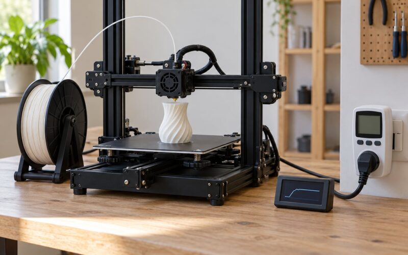
Your corners lift because the plastic contracts as it cools, and at a corner there is the least material holding that contraction down. Sharp corners cool fastest, the middle of a part stays warm longest, so the pull concentrates at the sharpest, thinnest points. Add a contaminated build plate, a Z offset that is a fraction too high, a draft from an air conditioner, or a high-shrinkage material like ABS, and the shrink force wins against bed adhesion. That is why does my 3d print warp at the corners is nearly always an adhesion or temperature problem rather than a broken printer.
Good news: it is also one of the most fixable problems in FDM printing. I have walked through this same sequence on flat test squares, tall brackets, and 300 mm bed parts, and almost every one of them came right after a plate clean and one temperature change. This guide is that sequence, in the order that wastes the least filament and filament change-outs.
Everything below assumes a desktop FDM printer. Resin printers have a completely different failure mode, and none of this applies to them.
Table of Contents
- 1Why Does My 3D Print Warp at the Corners?
- 2What Causes Corner Warp in FDM Prints?
- 3Why Are Corners More Likely to Lift Than the Center?
- 4How Material Shrinkage Changes Corner Warping
- 5How to Stop Corners from Warping
- 6Step 1: Read the failure pattern before changing anything
- 7Step 2: Clean the plate properly
- 8Step 3: Verify Z offset and bed leveling
- 9Step 4: Fix the first layer before you chase the corners
- 10Step 5: Change one temperature at a time
- 11Step 6: Control the chamber and the airflow
- 12Step 7: Only now change the model
- 13Fix the First Layers and Bed Adhesion
- 14Control Temperature, Cooling, and Airflow
- 15Change the Part If the Printer Settings Are Correct
- 16How to Diagnose the Exact Source of Corner Warp
- 17Frequently Asked Questions
- 18Why do only the corners of my 3D print lift?
- 19Should I use a brim or a raft for corner warping?
- 20Does a higher nozzle temperature stop corners from warping?
- 21How much does PLA shrink when 3D printing?
- 22Why does my 3D print warp only when printing ABS or ASA?
- 23Can bed adhesion spray fix corner lifting?
- 24What Should You Change First?
Why Does My 3D Print Warp at the Corners?
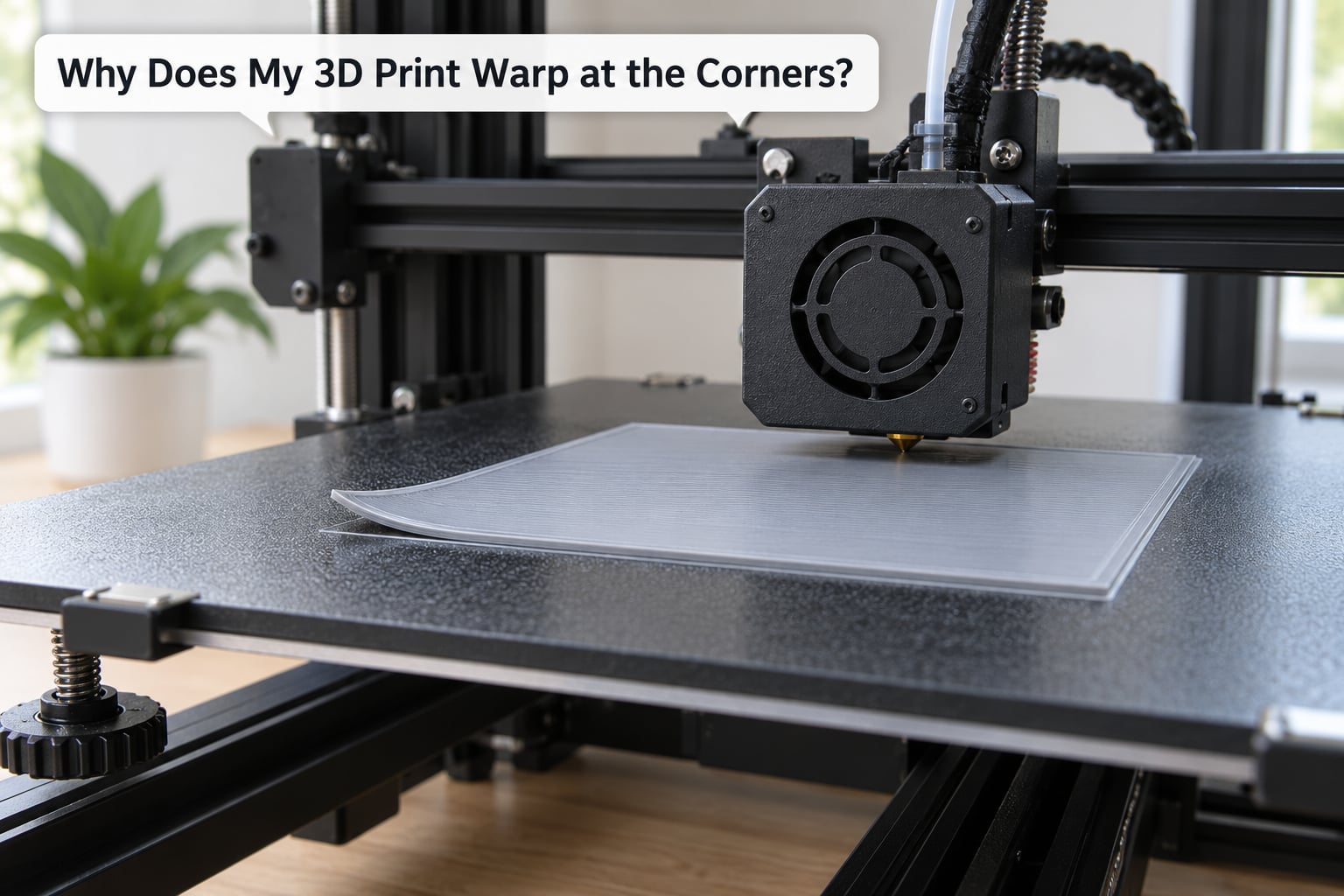
Corners warp because uneven thermal contraction and faster cooling pull harder on a small, unsupported piece of plastic than bed adhesion can resist. The stress concentrates at the sharpest points of the footprint, and it shows there first. A dirty plate, a slightly high Z offset, a cold room, a draft, or a high-shrinkage material all make the pull stronger or the hold weaker, so the corners lift while the center stays flat.
Here is the whole idea in one line: shrinking plastic pulls, the plate pushes back, and whichever force is larger wins. The plate is weakest at the extremes of the footprint, so you see it at the corners.
What Causes Corner Warp in FDM Prints?
Extruded thermoplastic behaves in a specific way. It comes off the nozzle somewhere around 200 to 250 degrees Celsius, expands as it warms, and then shrinks as it cools. The shrinkage is small in absolute terms but the forces it creates along a several-hundred-millimetre part are not small at all. If the part is free to shrink, nothing happens. If the first layer is stuck down and the rest of the part is held by only its own stiffness, the shrinking part has to go somewhere, and it curls upward to relieve the tension.
Several things stack up to create that condition:
- Thermal contraction. Every FDM material shrinks as it solidifies. Shrinkage figures vary widely by polymer, and the higher the number, the more force the part generates while cooling.
- Nonuniform cooling. The outer edges and corners of a print see more airflow and have more surface area relative to their mass, so they drop toward room temperature sooner than the center.
- Residual stress between layers. Each layer is stretched slightly as it is laid down and relaxes later. A part with poor interlayer bonding carries that stress all the way to the footprint instead of absorbing it.
- Bed adhesion. A contaminated, worn, or poorly prepared plate reduces the hold on the first layer. Once the first layer lets go at one point, the rest of the footprint follows.
- Geometry. Thin, sharp, or unsupported corners have less cross-section and less material to distribute the stress, and there is no neighbouring geometry to restrain them.
- Airflow. A part cooling fan aimed straight at one corner, an open door, or a room air conditioner gives that corner an unfair head start.
One distinction worth making early, because the fix is different: corner lift is not the same as general bed adhesion failure. If the whole print releases from the plate and the edges curl up all the way around, that is a plate preparation or Z offset problem. If the four corners barely move but the middle of a thin wall bulges, you are looking at cooling and overhang geometry instead. If one specific corner lifts every single time, suspect a cold spot or a mechanical issue on that side of the bed rather than a temperature setting.
Why Are Corners More Likely to Lift Than the Center?
Three reasons, and they compound each other. First, a corner has roughly twice the exposed surface per gram of plastic as the middle of a solid square, so it gives up heat faster. It reaches its glass transition temperature and goes rigid while the center is still soft and still shrinking, which means the corner is carrying the mismatch on its own.
Second, a corner is unrestrained. When a layer in the center contracts, neighbouring material on all sides resists it. At the corner there is nothing on two sides, so the contraction has an easy direction to go, and that direction is up and away from the plate.
Third, airflow is rarely symmetrical. The nozzle blows a small amount of air across the fresh layer on every pass, the print fan adds more, and the room adds the rest. A part rotating under a fixed fan gets uneven treatment, and a small square in the middle of the bed sits right in the corner region where the fan duct is aimed.
This is also why small, sharp, 90 degree features fail worst. A 40 mm square with 2 mm corner radii behaves very differently from a 40 mm square with 8 mm fillets, even printed with identical settings. Rounding the corner gives the shrinking material somewhere to compress into instead of concentrating the whole force on a single line.
How Material Shrinkage Changes Corner Warping
Material choice sets the ceiling on how hard the part pulls, and no slicer setting can beat a material that shrinks too much for your machine. These are typical linear shrinkage values for well-dried filament printed within its recommended range.
| Material | Typical linear shrinkage | Warp risk on an open-frame printer | Starting bed temperature |
|---|---|---|---|
| PLA | about 0.3 percent | Low, usually only with a dirty plate or a draft | 55 to 60 degrees Celsius |
| PETG | about 0.4 percent | Moderate, mostly the tall thin part crowd | 75 to 85 degrees Celsius |
| ABS | about 0.7 percent | High without a heated chamber | 100 to 110 degrees Celsius |
| ASA | about 0.7 percent | High without a heated chamber, UV stable outdoors | 100 to 110 degrees Celsius |
| Nylon | up to 1.5 percent | High, and very sensitive to moisture in the filament | 70 to 80 degrees Celsius |
| PA-CF | similar to nylon | High, plus abrasive nozzle wear | 80 to 90 degrees Celsius |
| TPU | low, flexible after printing | Low if the base is fully supported | 30 to 45 degrees Celsius |
ABS and ASA behave the way they do because their glass transition temperature sits close to the temperature of a typical room, so they keep shrinking and creeping long after the print ends. That is the entire reason enclosed printers exist for engineering work. Community data on ABS warping puts open-frame failure somewhere in the 30 to 60 percent range for large flat parts, dropping to roughly 2 to 5 percent inside a heated chamber. PLA on the same open machine fails in the low single digits.
Moisture works the same way. Wet filament prints with a rough, pitted surface, weak layer bonding, and visible bubbles or stringing in the flow line, and it sheds extra shrinkage stress because the layers do not fuse properly. A simple overnight filament dryer, or a food dehydrator set low and left on a timer, fixes more corner-lift cases than people expect.
How to Stop Corners from Warping
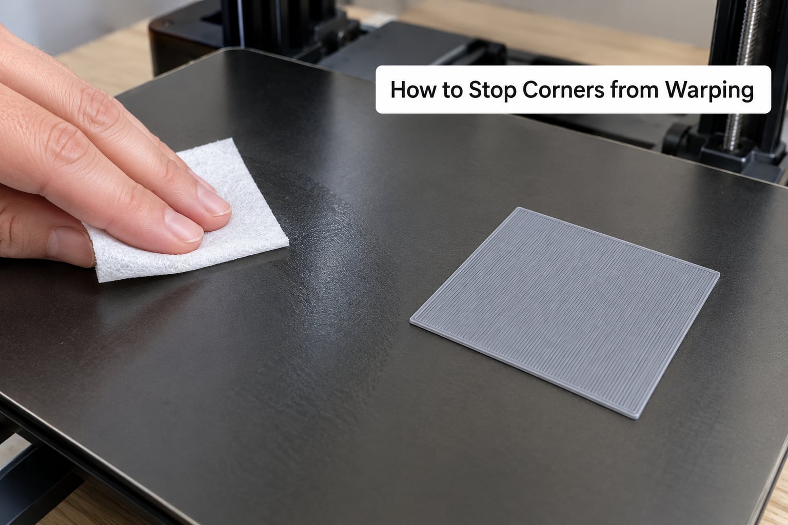
Work down this list in order and stop as soon as the print comes off flat. Each step is cheap, and skipping ahead to brims and glue wastes hours on a problem that a single wipe of the plate would have solved.
Step 1: Read the failure pattern before changing anything
Pull the failed part off the plate and look at where it released. All four corners and nothing else points at bed temperature or the plate. One corner that repeats every print points at a cold spot, a sheet that is not seated flat, or a warped bed. Corners that start about a centimeter up rather than at the first layer are a cooling and overhang problem, not bed adhesion. Ten minutes of looking saves an evening of guessing.
Step 2: Clean the plate properly
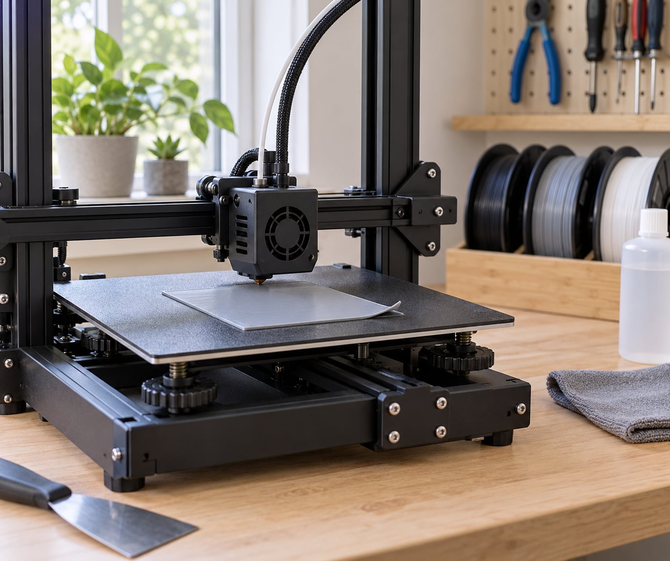
Wash the sheet with warm water and dish soap, rinse it, and dry it. Then wipe it with 90 percent isopropyl alcohol before every print. Fingerprints, skin oil, dust, and previous layer residue are the single most common cause of corner lift, and no amount of temperature tuning compensates for a greasy footprint. Use the textured side for textured PEI and the smooth side for smooth PEI, and never swap a sheet between printers without cleaning it.
Step 3: Verify Z offset and bed leveling
Run the printer’s first layer or a single layer test and look at the lines. Separate, wobbly, blobby lines mean the nozzle is too low, while lines that show the outline of the nozzle and a visible gap between them mean it is too high. Corners are where a mesh bed or a warped spring steel sheet usually shows its error first, so a square test catches what a straight line across the middle will not.
Step 4: Fix the first layer before you chase the corners
Set the first layer speed slower than the rest of the print. In PrusaSlicer, OrcaSlicer, and Cura the field is under the first layer tab, next to the layer height and initial line width. A slower first layer gives the plastic time to wet into the plate texture and form a mechanical bond, and a full-width or wider first layer line adds more contact area under exactly the regions that lift. Once the first layer is right, most corner problems go quiet without touching anything else.
Step 5: Change one temperature at a time
Raise the bed temperature in 5 degree Celsius steps and leave it there through the whole print, then repeat the test square. If nothing changes after two steps, change something else and come back. Moving the nozzle, the bed, the fan, and the speed together is the most common reason people never find the actual cause.
Step 6: Control the chamber and the airflow
Close the doors on an enclosed printer, or build a cardboard draft shield around the bed on an open frame. Then look at the part cooling fan: a duct aimed straight at one corner will cool that corner harder than the rest. Turning the fan down for the first 8 to 10 layers buys the base time to stay warm, and raising it for overhangs later gives you the layer bonding you need up top.
Step 7: Only now change the model
If the square prints flat and the real part still lifts, the problem is in the geometry, not the machine. Add a brim, add mouse ears, or reorient the part. The next two sections cover what each of those does.
Fix the First Layers and Bed Adhesion
Everything about the first layer comes back to one idea: more contact area, held longer, on a clean surface. The adhesion force a part can generate is roughly the contact patch multiplied by how well the plastic wets into the plate texture, and a corner has the least material above it to resist the lift in the first place.
Plate cleanliness and surface choice come first. Clean textured PEI with soap and water and a little scrubbing if the texture has filled in with burnt plastic, then finish with isopropyl alcohol. A smooth PEI sheet is the safer surface for PETG and ABS because those materials can bond chemically and eventually tear the coating, while textured PEI grips PLA without much help. If prints start releasing suddenly after months of working, the sheet is usually worn out rather than the settings being wrong.
Nozzle height is next. A Z offset that is even 0.05 mm too high leaves the footprint with gaps between the lines, and a corner with gaps has almost no grip. A Z offset that is too low squashes the layer so hard that the plastic gets pushed sideways into a ridge, which is a different problem: the print sticks well but the base edge bulges. The ugly wide skirt around the first layer is the symptom people usually notice, not the corner lift it causes later.
Then tune the first layer itself. Slower first layer speed, a slightly wider initial line width, and a 100 percent or higher first layer flow rate all increase contact. Whatever your slicer calls it, the options are Initial Layer Speed, First Layer Line Width, and Initial Layer Flow.
Adhesion products are the last step on this list, not the first. Glue stick works well on bare glass for PETG. A slurry of ABS dissolved in acetone, applied to a clean plate and allowed to dry, is the standard trick for ABS and ASA on glass. Hairspray, used sparingly on a clean plate, is a cheap adhesion booster and it fixed a long-running PETG corner lift case in a thread on the Prusa community forum, combined with a brim and a small bed temperature increase. Slurry, glue, and hairspray all need a clean plate underneath and all of them stop working once the layer gets hot enough to let go, so treat them as a bonus on top of good settings rather than a fix.
Control Temperature, Cooling, and Airflow
Temperature controls how much the part shrinks and how long it stays flexible enough to relieve that shrinkage. It is the strongest lever you have, and it is also the one people are most likely to overdo.
| Material | Nozzle starting range | Bed starting range | Part fan notes |
|---|---|---|---|
| PLA | 200 to 215 degrees Celsius | 55 to 60 degrees Celsius | Minimum for the first 8 to 10 layers |
| PETG | 235 to 250 degrees Celsius | 75 to 85 degrees Celsius | Low, PETG already cools slowly |
| ABS | 245 to 260 degrees Celsius | 100 to 110 degrees Celsius | Keep low and use a chamber above 45 degrees Celsius |
| ASA | 245 to 260 degrees Celsius | 100 to 110 degrees Celsius | Keep low, UV stable for outdoor parts |
| Nylon and PA-CF | 260 to 280 degrees Celsius | 70 to 90 degrees Celsius | Dry filament first, then low fan |
A hotter nozzle raises the layer temperature and slows the drop toward ambient, which buys time for the new layer to fuse into the one below. It also increases the size of the thermal window the part has to shrink inside, so pushing the nozzle too high makes warping worse. If your corners lift and the surface looks slightly glossy from stringing, back the nozzle down 5 degrees at a time.
A hotter bed works differently. It keeps the bottom of the part, the layers right on top of the plate, above its glass transition temperature, so those layers keep flowing slightly and can absorb the first few layers of shrinkage instead of fighting it. That is why bed temperature is the single most effective setting for corner lift, and why it should be the first temperature you change.
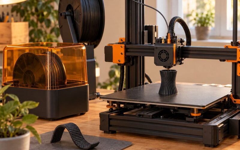
Chamber temperature is what separates a printer that handles ABS from one that does not. Once the whole chamber sits above 45 degrees Celsius, ABS parts cool slowly enough to stay relaxed through the print. A draft shield around the bed, sometimes called a full height skirt, is a cheap approximation for open-frame machines and was one of the suggestions that came out of that same Prusa thread. Ambient conditions matter too: a printer in a cold garage or a room with an air conditioner running will warp parts that behave perfectly on a desk.
Layer time is the quiet variable. A small part on a fast machine can be printed with so little time between layers that the fan barely matters, while a large part with many perimeters spends minutes per layer and ends up over-cooled. Slowing the first several layers, or raising the minimum layer time in the slicer, is a cheap experiment when only tall parts are affected.
Change the Part If the Printer Settings Are Correct
Once a flat test square prints flat on the same machine with the same filament, the remaining variables live in the model. These changes buy the part more contact area, more restraint, or less stress at the corner.
Brim. A flat ring of extra material around the footprint, ideal for tall thin objects and small parts with a small contact area. It adds no height, so it is the right choice for parts you do not want to post-process off the plate.
Raft. Several full layers underneath, which is more support than a brim and useful for models that need a flat underside anyway. It costs more time and filament, and a poorly tuned raft can lift on its own and take the print with it.
Mouse ears. Small pads of material, usually 5 to 10 mm across, added at each corner. They multiply the contact area exactly where the force concentrates and they are standard practice in the Voron community for large ABS parts. Slicers such as PrusaSlicer and OrcaSlicer include a setting for them, or you can model them in.
Fillets and chamfers. A 3 to 5 mm radius on the corner of the footprint spreads the contraction over a curve instead of concentrating it on a line. This is a drawing change rather than a slicer change, and it often works where a brim does not.
Orientation. Turning the part so the largest flat face is not the only thing holding the part down, or splitting a large part into sections printed individually and assembled, removes the long unsupported span entirely. For tall thin parts, rotate the part so the thin direction is no longer fighting the layer lines.
Supports under overhangs. Corner curl that starts a centimeter up and follows a steep overhang is a support problem. A Bambu Lab community thread on corner bending that started above the first layer landed on supports, longer layer times, and a higher Z hop to stop the nozzle catching the curled edge, not on bed temperature.
None of these repair a dirty plate or a bad Z offset. They buy the part margin while you fix the settings underneath.
How to Diagnose the Exact Source of Corner Warp
Find your symptom in the table and start there. It saves the blind tweaking that most troubleshooting threads turn into.
| What you see | Most likely cause | Where to start |
|---|---|---|
| All four corners lift, center stays flat | Bed adhesion losing to shrinkage | Clean the plate, then raise bed temperature in 5 degree steps |
| One specific corner lifts every time | Cold spot, uneven bed, or a sheet that is not seated flat | Check the bed cable and mesh spacing, inspect the sheet, test with the part rotated 90 degrees |
| Corners start lifting about a centimeter up | Cooling and overhang stress, not bed adhesion | Reduce fan, add supports, increase layer time |
| Only the corners lift, edges and center are perfect | Small contact area on a small part | Add a brim, add mouse ears, or enlarge the first layer line width |
| Corners lift only in ABS or ASA | High shrinkage plus a cold chamber | Enclose the printer and heat the chamber, or switch to PLA for the test |
| Corners lift only in PLA | Contamination, draft, or a high Z offset | Isopropyl clean, close the door, run a first layer test |
| Tall thin parts curl, flat squares are fine | Part cooling overpowering layer bonding up top | Lower the fan, raise the nozzle 5 degrees, slow the outer wall |
| A brim is on and the corners still lift | The problem is above the plate, so the brim cannot help | Check airflow on the corners and overhang geometry instead of bed adhesion |
| Prints started failing after months of fine results | Worn or contaminated plate surface | Deep clean or replace the sheet, then recalibrate Z offset |
| Surface looks rough, flow line shows bubbles | Wet filament | Dry the spool, then reprint the same file |
Two patterns deserve their own note. A brim that fails to help is usually a sign the problem started above the first layer, since a brim only adds footprint and footprint helps the first layer. And one persistent corner across many different parts on one machine is worth treating as hardware until proven otherwise: check the heated bed cable, the corner screws, the sheet seating, and the mesh or spring steel flatness before touching any slicer setting.
Frequently Asked Questions
Why do only the corners of my 3D print lift?
Corners are the only part of the footprint with material on one side instead of all four, so thermal contraction pulls there first with nothing to resist it. They also cool faster and get more airflow than the center. A small part with sharp 90 degree corners concentrates more force than a large one with fillets. Fix the plate and Z offset first, then add a brim or mouse ears if the base is already clean and level.
Should I use a brim or a raft for corner warping?
Start with a brim. It adds contact area around the footprint at almost no cost, and it works well for tall thin parts and small bases. A raft adds several full layers of support, which helps models that need a flat underside but wastes time and can detach on its own. Neither replaces a clean plate and a correct Z offset, because both only enlarge the area that is already sticking down.
Does a higher nozzle temperature stop corners from warping?
It helps within a range, and it hurts outside that range. A hotter nozzle keeps each layer softer for longer, so the next layer fuses better and the part has more time to relieve shrinkage. Pushing it too high adds more shrinkage to manage and shows up as stringing and gloss. If corners lift, raise the nozzle 5 degrees at a time and stop as soon as the surface quality drops. Bed temperature usually has more effect on corners.
How much does PLA shrink when 3D printing?
Well-dried PLA printed in its normal temperature range typically shrinks about 0.3 percent linearly, which is low compared with ABS at roughly 0.7 percent or nylon at up to 1.5 percent. That low figure is why PLA usually prints flat on an open-frame machine. When PLA corners still lift, the cause is usually contamination, a draft, or a Z offset that is slightly too high rather than the material itself.
Why does my 3D print warp only when printing ABS or ASA?
ABS and ASA shrink more than PLA and keep shrinking after the print because their glass transition temperature sits near room temperature. On an open-frame printer the part cools from a cold chamber, so that shrinkage has nowhere to go and the corners lift. An enclosure with the chamber above about 45 degrees Celsius solves most of it, and community estimates put open-frame ABS failure rates for large flat parts in the 30 to 60 percent range.
Can bed adhesion spray fix corner lifting?
Sometimes, and it works best on a glass or smooth PEI plate that is properly cleaned first. Hairspray and similar sprays add a sacrificial layer that raises adhesion, and a combination of spray, a brim, and a small bed temperature increase solved a recurring PETG corner lift case in a Prusa community forum thread. Treat it as a bonus rather than a fix, since the bond weakens at the higher bed temperatures high-shrinkage materials need.
What Should You Change First?
Start with the plate. Wash it, wipe it with isopropyl alcohol, and print a first layer test square so you can see exactly where the lines gap or blob. If that square is clean all the way to the corners, the base is fine and the problem lives above it.
Next, work through the geometry, the airflow, and the material, changing one thing at a time and reprinting the same file each time. Answering why does my 3d print warp at the corners is rarely a single setting, so isolating one variable per test is what actually finds the cause. Keep the diagnostics from the table nearby, and recheck for a cold plate or a worn sheet whenever a fix seems to work for a few prints and then quietly stops.