For most functional FDM parts, 30-40% infill with three or four walls and a cubic, gyroid or tri-hexagon pattern is the sweet spot for strength. Walls carry most of the load, so adding a perimeter buys more than adding density does. Above roughly 35-40%, extra infill adds filament and time for very little stiffness in return.
That is the short answer, and it covers maybe half the cases where people ask how to choose infill percentage for strength. The other half comes down to what the part actually has to do: a wall hook that swings, a jig that holds a part under load, a shim that flexes, or a bracket bolted to something heavy. Density is one variable among several, and it is often not the biggest one.
This guide walks through the decision in order — define the load, pick a starting percentage, match the pattern to the direction of stress, adjust walls and orientation, then prove it with a coupon. It takes about twenty minutes to work through and most of an evening of printing to test properly.
Table of Contents
- 1What You Need
- 2Step-by-Step
- 31. Define the load the part must carry
- 42. Choose a starting infill percentage for strength
- 53. Select an infill pattern for the load direction
- 64. Adjust shells, layer height, and orientation
- 75. Test before printing the final part
- 8Common Mistakes
- 9Frequently Asked Questions
- 10Is 100% infill always the strongest 3D print setting?
- 11What infill percentage should I use for a functional 3D-printed part?
- 12Does more infill always make a 3D print stronger?
- 13Is grid infill stronger than gyroid infill?
- 14How many walls should I use instead of high infill?
- 15What is the best way to test infill percentage for strength?
- 16Conclusion
What You Need
Before touching a slicer slider, gather a few things. Without them you are guessing, and guessing costs filament.
- A description of the load. Static and steady, or shock and impact? Hot or room temperature? Vibrating? A part in a car dashboard sees vibration and heat at once, which is a different problem from a shelf bracket holding books.
- The material you will actually print. PLA, PETG, ABS, ASA, nylon, TPU or a fibre-filled variant each behave differently, and the sensible density range moves with them.
- Your printer’s constraints. Nozzle diameter, maximum volumetric flow, and whether your machine can push enough plastic to fill dense sections without underextruding.
- Access to your slicer. PrusaSlicer, Cura, OrcaSlicer and Bambu Studio all expose every setting discussed here.
- One representative test coupon. A simple bracket-shaped or beam-shaped part that mirrors the real geometry, roughly the same wall thickness, small enough to print three variants overnight.
- A way to apply a known load. A bench, a clamp, a spring scale or a stack of weights. Even a rough comparison tells you more than an opinion.
Step-by-Step
1. Define the load the part must carry
Sorting parts into four buckets gets you most of the way there before any setting is chosen.
- Decorative. Models, figurines, display pieces, vases. These carry no structural load at all. 10-20% is plenty, and the surface finish matters more than anything under the skin.
- Lightly loaded. Phone stands, desk organisers, drawer dividers, light brackets. 15-25% with three walls handles this comfortably.
- Impact-prone. Tool handles, bumpers, grips, anything dropped or knocked. These need walls more than density, because impact failure is a toughness problem rather than a stiffness problem. 20-30% with four or five walls.
- Heavily loaded or safety-relevant. Load-bearing mounts, hooks holding real weight, jigs and fixtures under repeated clamping. 40-60% with three or four walls, and then test.
Sandwich panel theory explains why that last bucket still does not need solid plastic. A thin shell of material held far from the neutral axis resists bending far better than a thick lump of material concentrated in the middle.
2. Choose a starting infill percentage for strength
Start low, then add walls before adding density. These are starting points, not verdicts.
| Use case | Walls | Top and bottom layers | Pattern | Infill % |
|---|---|---|---|---|
| Display model | 2-3 | 3 | Grid or lightning | 10-15 |
| Everyday functional part | 3 | 4 | Grid or cubic | 20-25 |
| Bracket or hook | 4 | 5 | Cubic or gyroid | 30-40 |
| Jig, fixture or clamp | 4-5 | 5-6 | Gyroid or tri-hexagon | 40-50 |
| Repeated high load | 5 | 6 | Cubic or tri-hexagon | 50-60 |
| Water-tight or heavily machined | 4 | 6 | Cubic | 80-100 |
The knee of the curve usually sits between 35% and 60%, depending on pattern and material. Below that knee, each extra point of density meaningfully stiffens the part. Above it, you are mostly adding weight.
Material shifts the range. PLA and PETG behave well in the middle bands. ABS and ASA tolerate more density because they tolerate heat and stress better. Nylon wants higher density for functional work. Fibre-filled PLA and PETG often want less, because the fibre already contributes stiffness and dense short-fibre sections bridge badly, producing voids.
3. Select an infill pattern for the load direction
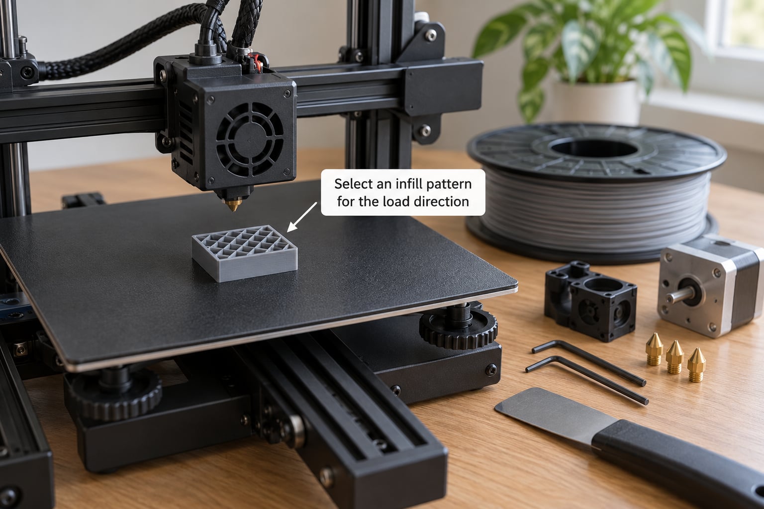
Pattern choice decides how a part handles stress from a particular direction. A pattern that is excellent under one load can collapse under another.
- Cubic. Load-bearing in the X and Y directions, strong and predictable, and prints cleanly. A solid default for brackets and mechanical parts.
- Gyroid. A single continuous curved surface that resists load from almost any direction in the XY plane. Prints fast, uses little material, and bends rather than snapping. The most popular all-round choice.
- Grid (rectilinear). Strong along X and along Y, weak in between. Fine for slow static loads, poor for anything that twists.
- Tri-hexagon. Triangles resist deformation better than squares, so it outperforms grid at the same density. The reason many references recommend low densities with a strong pattern.
- Lightning. Very fast and light. Fine for decorative and lightly loaded parts, poor for real structural work.
- Concentric. Nested rings. Good for round parts such as tubes and bushings, since it stays aligned with the circumference.
- Honeycomb. Efficient in compression, gentler on the extruder than solid-dense options, and a common choice for TPU bumpers.
This is where conflicting advice online usually comes from. Some sources say cubic or gyroid at 15-25% for maximum strength; others say 40-60%. Both can be right, because they are answering different questions. At low densities, pattern choice dominates and a strong pattern at 20% beats a weak pattern at 40%. At high densities, every pattern is surrounded by solid material and the difference mostly disappears.
Changing orientation can matter as much as changing percentage. If a bracket’s bolt holes are loaded along an axis where the pattern is weak, rotating the part in the slicer or on the bed often does more than any infill adjustment.
4. Adjust shells, layer height, and orientation
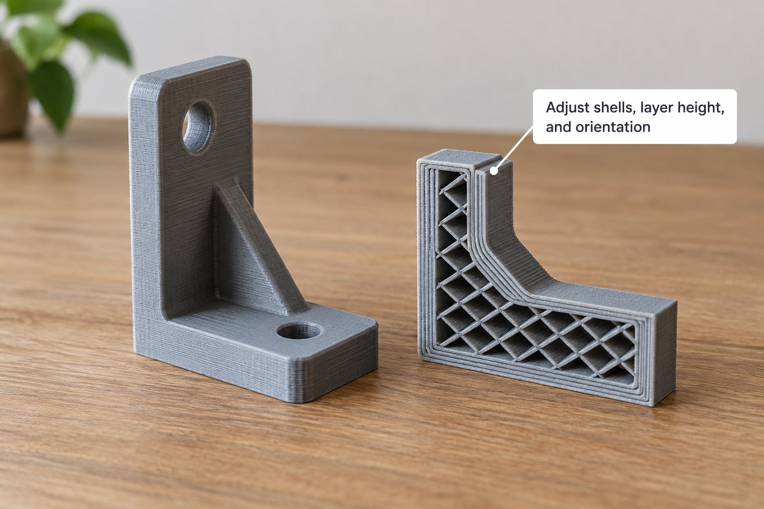
Most of your strength lives outside the infill. Walls sit at the edge of the cross-section where they do the most work per gram of plastic, and the solid top and bottom layers carry load that travels along Z.
Move from three walls to five and you gain more real strength than moving from 20% to 60% infill, usually at a fraction of the added material. Increase top and bottom layers whenever the load tries to pull the faces apart.
Layer height has a smaller effect than most people expect. Thinner layers mean more inter-layer bonding opportunities, so a thin-layer print survives Z-direction pulls better, but the cross-section of the whole part stays the same. Keep layer height under half your nozzle diameter and stop obsessing over the difference between 0.16 and 0.20.
Orientation is the one setting that cannot be worked around. A part printed on edge, with its load path running along the layers, will be dramatically stronger than the same part printed flat. Z-axis strength is limited by how well the hot nozzle fuses each new layer to the one below, and no infill percentage fixes that. A large flat surface pressed against another flat surface is where the weak axis lives, so orient parts so those surfaces are not the load path.
Two smaller settings matter more than people expect: infill overlap, the percentage by which infill strands reach into the walls, and underextrusion at high density. Overlap below about 10% leaves infill barely attached to the shell. Above roughly 80% density the nozzle cannot lay plastic fast enough, so you get voids inside a part that is supposed to be solid.
5. Test before printing the final part
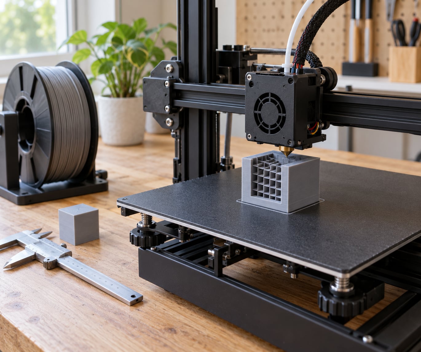
A coupon test turns opinion into evidence, and it is the step most people skip. Print three variants: your current setting, one with two extra walls, and one at roughly 20% higher density.
Keep everything else identical — same filament batch, same layer height, same orientation, same ambient temperature, same machine. If you change two things at once you learn nothing from the result.
Print them flat and, if the real part has an orientation you care about, print one variant in that orientation too. Then apply load gradually and record where and how each coupon fails.
The failure mode tells you more than the raw number. A break straight through a layer line means your Z-bonding or orientation is the problem, and more infill will not help. A break where the wall tore away from the infill means overlap is too low or density is too high for the flow. A gradual sag means the part was simply under-dense for the load.
Write down the settings that worked. Three coupons take one evening and save you from a failed 30-hour part.
Common Mistakes
Assuming 100% infill is always the strongest. Past roughly 60% you gain almost no stiffness for a large jump in filament and time, and a fully solid section has less room to absorb a shock. Solid PLA in particular tends to feel brittle and fail more suddenly than a 30-40% gyroid part under a knock.
Using a pattern that fights the load. Grid infill on a part loaded in shear is close to leaving the middle of the part empty. Match the pattern to the direction of stress or print a trial in a different orientation.
Ignoring layer adhesion. The weakest axis of any FDM part runs between layers. If the part snaps along a layer line, raising density is the wrong fix — change orientation or improve the surface and temperature conditions.
Printing one coupon and calling it a test. One print tells you it held or it broke. Two or three, with one variable changed at a time, tell you which setting did the work.
Never opening the slicer preview. Slice the part, step through the preview, and read the time estimate. If the estimate doubled after a 15% density change, the time cost is not what you expected.
Copying a default. Slicers ship with settings tuned for appearance and general use. They are a starting point, not an answer for a part under load.
Frequently Asked Questions
Is 100% infill always the strongest 3D print setting?
No. Above roughly 60% infill, added density contributes very little extra stiffness while filament use and print time climb sharply. Fully solid sections can also behave more brittly under impact than a part with 30-40% gyroid, because there is less internal structure to absorb a shock. Reserve 80-100% for cases that genuinely need it: water-tight vessels, parts that will be machined afterwards, or thin shapes with no room for many walls.
What infill percentage should I use for a functional 3D-printed part?
For most functional parts, 30-40% with three or four walls is the reliable range. Lightly loaded items such as phone stands and desk organisers are fine at 15-25%. Jigs, fixtures and load-bearing brackets sit at 40-50%, and anything taking repeated heavy load goes to 50-60%. Material matters too: nylon tends to want more density, fibre-filled filaments usually want less. Treat these as starting points and confirm with a coupon test.
Does more infill always make a 3D print stronger?
Up to a point, yes, then no. Strength rises meaningfully between about 10% and 35-40% depending on pattern and material, which is the useful range. Past the knee of the curve you are mostly adding weight and print time. Walls at the edge of the cross-section do more for bending strength per gram than infill in the middle, so adding a perimeter usually beats adding 20 points of density.
Is grid infill stronger than gyroid infill?
It depends on direction. Grid infill is strong along X and along Y but weak diagonally, so it performs well under steady aligned loads and badly under twisting or shear. Gyroid forms one continuous curved surface that carries load in many directions in the XY plane and tends to bend rather than snap. For a general-purpose part with no obvious load axis, gyroid is the safer pick at the same density.
How many walls should I use instead of high infill?
Three walls is a sensible minimum for functional parts, and four or five suits anything under real load. Going from three walls to five generally gains more usable strength than jumping from 20% to 60% infill, and it costs far less material because wall lines are laid around the whole cross-section rather than filling it. Add top and bottom solid layers as well whenever the load tries to separate the faces.
What is the best way to test infill percentage for strength?
Print three identical coupons that mirror your real part’s geometry and wall thickness: your current setting, one with two extra walls, and one at about 20% higher density. Change only one variable at a time, use the same filament and orientation for all three, then apply load gradually and note the failure load and where the part broke. The failure location tells you whether density, walls or orientation was the real limiting factor.
Conclusion
Knowing how to choose infill percentage for strength comes down to sequence, not a magic number. Start at 30-40% with four walls and a cubic or gyroid pattern, orient the part so the load runs along the layers rather than across them, then print three coupons before committing to the real one. If it snaps along a layer line, change the orientation, not the density. Most parts are solved by walls and layout long before anyone needs another twenty points of infill.