Photogrammetry for 3D printing is the process of photographing one object from many overlapping angles, letting software work out the distance and shape of every surface point, then turning that data into a mesh you can repair and slice. The short version: you need a camera, an object with texture, even light, and patience through the mesh cleanup stage.
Most people get the capture part right on the first or second try. The part that stalls beginners is cleanup, because the file the software hands you is a crumpled shell of the object, not something a printer can use. This guide walks the whole pipeline, from taking the pictures to exporting an STL that a slicer accepts.
Table of Contents
- 1What Is Photogrammetry for 3D Printing?
- 2How Does Photogrammetry for 3D Printing Work?
- 3Photogrammetry for 3D Printing Workflow at a Glance
- 4What Can You Scan With Photogrammetry?
- 5What Equipment and Software Do You Need?
- 6How Do You Prepare an Object for a Good Scan?
- 7How Do You Capture the Photos?
- 8How Do You Turn the Photos Into a 3D Model?
- 9How Do You Make the Scan 3D-Printable?
- 10How Accurate Is Photogrammetry for 3D Printing?
- 11Frequently Asked Questions
- 12Can photogrammetry scans be used directly for 3D printing?
- 13Do you need a turntable to do photogrammetry?
- 14How many photos are needed for a 3D scan?
- 15What is the best phone or camera for photogrammetry?
- 16Can photogrammetry scan a person, terrain, or mechanical part?
- 17Why does my photogrammetry model have holes or floating pieces?
- 18Conclusion
What Is Photogrammetry for 3D Printing?
Photogrammetry is a way of measuring shape from ordinary photographs. Software finds the same feature points in overlapping images, uses the small shifts between them, known as parallax, to work out how far away each point is, and builds a three-dimensional model from those measurements.
The result comes in two forms, and the difference matters for printing. A textured scan keeps the surface colour and detail, so it looks like the object when viewed on screen. A printable mesh strips that texture away and leaves raw geometry, which the printer needs because a colour map is not something a plastic printer reads.
Almost every scan needs work between those two forms. That is the honest part of photogrammetry for 3D printing: the measurement is automatic, the file preparation is hands-on.
How Does Photogrammetry for 3D Printing Work?
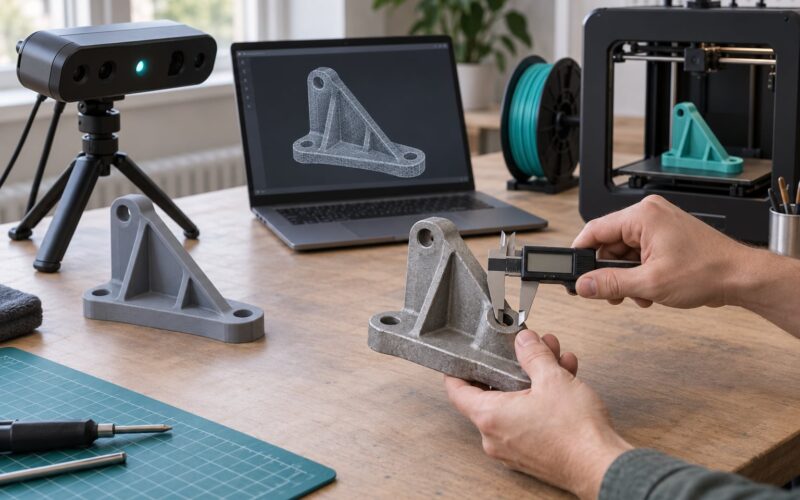
The pipeline runs in a fixed order, and it is worth knowing all of it before you start shooting.
- Capture. You photograph the object from dozens of angles so every visible surface appears in at least two, ideally several, photographs.
- Feature detection. Software hunts for distinctive spots on the object, corners, edges, texture speckles, and labels them as candidates for matching.
- Feature matching. It compares candidates across overlapping frames to find the same point seen twice.
- Camera position estimation. From the parallax between matched points, the software solves for where the camera was standing for every frame.
- Dense reconstruction. Once positions are known, it calculates a three-dimensional point for far more pixels than were matched, producing a dense point cloud.
- Mesh generation. A surface-fitting step wraps triangles around the point cloud. This is where a first mesh appears, complete with stray surfaces from the background.
- Cleanup. You delete the floor, close holes, flatten the base, and cut the polygon count down to something a slicer can handle.
- Export. The repaired mesh is saved as STL, OBJ, PLY, or 3MF, scaled in millimetres, ready for the slicer.
Structuring this in your head before the first photo usually saves a second scan. You know which stage is going to go wrong and what to check when it does.
Photogrammetry for 3D Printing Workflow at a Glance
| Stage | What goes in | What comes out | Check before moving on |
|---|---|---|---|
| Capture | Object, camera, light | Overlapping image set | Every angle covered, frames sharp |
| Alignment | Image set | Sparse point cloud | Preview shows no stretched or floating geometry |
| Dense cloud | Sparse cloud | Dense point cloud | Gaps inspected, reshoot if the missing area is large |
| Mesh | Dense cloud | Rough surface mesh | Background surfaces deleted |
| Cleanup | Rough mesh | Watertight solid | No holes, no inverted faces, closed base |
| Prep | Watertight mesh | Sliced file | Scaled in millimetres, walls above nozzle width |
That table is also a troubleshooting map. Each check is the place where a specific failure shows up first, and fixing it there is much cheaper than repairing it downstream.
What Can You Scan With Photogrammetry?
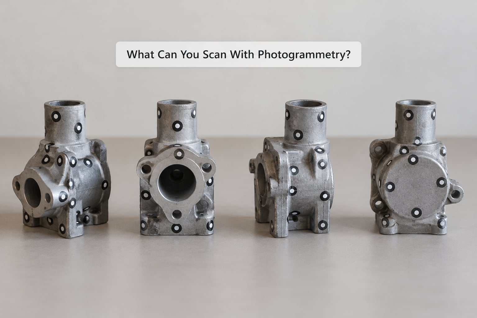
Photogrammetry works best on objects that are opaque, matte and irregular. Natural bumps, casting texture, fabric weave, wood grain and paint wear all give the software something to lock onto.
| Subject | How it behaves | What to change |
|---|---|---|
| Figurines and miniatures | Excellent with paint texture, usually the easiest first project | Avoid glossy varnish; shoot close |
| Small mechanical parts | Good, but recesses stay dark | Fill a scanner with coded targets, add side light |
| Toys and collectibles | Good on matte plastic and rubber | Mattify chrome and metallics |
| Cosplay props and armour | Good on large curved surfaces | Plenty of overlap at full size, work in sections |
| People and pets | Works, but movement ruins frames | Very still subject, many overlapping angles, high frame count |
| Terrain and rocks | Strong results outdoors | Flat overcast light, avoid shadows, scale marker for size |
| Shiny chrome, glass, acrylic | Fails or comes out warped | Matte spray or powder, change the surface entirely |
| Flat, featureless panels | Fails, no features to match | Adhesive targets, or add temporary texture |
| Thin, see-through parts | Unreliable, light passes through | Back the object with a matte card |
| Deeply recessed interiors | Often missing or filled in | Fish, blur, or segment them separately |
Repeated patterns cause a subtler problem. A row of identical holes or a tiled surface gives the matching stage several equally valid answers, and the reconstruction twists. Breaking up the pattern with temporary marks is usually enough.
What Equipment and Software Do You Need?
The honest answer is that a phone and a free app are a legitimate endpoint, not a compromise. Many makers start on a phone, understand the workflow, and only then decide whether a dedicated setup is worth it for them.
| Setup | What you need | Control | Best for |
|---|---|---|---|
| Phone and app | Smartphone, a photogrammetry app, diffuse light | Low | Your first scans, figurines under 20 cm |
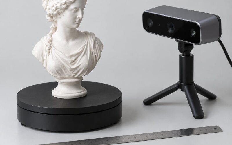
| Phone on a turntable | Tripod or phone clamp, turntable plate, remote shutter | Medium | Consistent, repeatable small-object scans |
| Camera and lens | Mirrorless or DSLR, 35 to 85 mm, tripod, light | High | Fine detail, larger objects, batches of scans |
| Multi-camera rig | Several phones, a printed or printed-and-assembled frame | High | Moving subjects and anything that cannot sit still |
On the software side, mobile apps such as Polycam, KIRI Engine, Scaniverse and Trnio run the whole pipeline on the phone and upload for cloud processing. Desktop reconstruction suites, including Agisoft Metashape, RealityCapture and AliceVision Meshroom, give you control over alignment accuracy, coordinate systems and processing quality.
Mesh repair is a separate choice from reconstruction. MeshLab, Meshmixer and Blender between them cover nearly every repair operation a hobbyist needs, and all three are free, so the cleanup stage does not need a purchase.
Two items matter more than the camera. A tripod or stable clamp, so framing does not wobble between shots, and a matte backdrop in a single tone, so the background does not compete for the matching stage’s attention.
How Do You Prepare an Object for a Good Scan?
Preparation is the cheapest quality improvement available. Ten minutes here routinely beats an hour of re-shooting later.
- Clean and dry the surface. Dust and fingerprints are texture that moves between frames, and the matching stage treats them as errors.
- Make the surface matte. A thin layer of mattifying spray, or a light dusting of powder, gives reflective plastic and metal something to track.
- Break up flat or repeating areas. Adhesive coded targets or a temporary scribbled texture give the software distinctive points to match.
- Decide on the background. A plain sheet with no seams and no clutter reduces the number of stray surfaces you delete later.
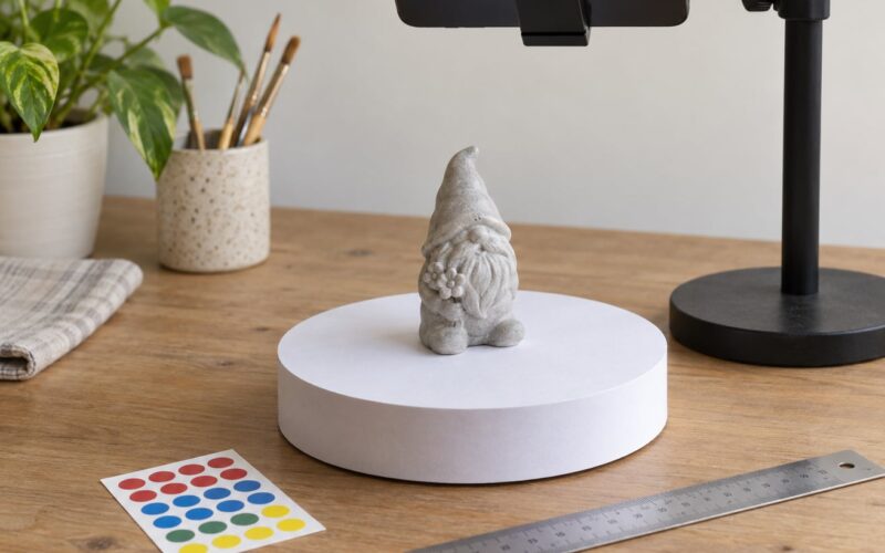
- Put something in for scale. A printed calibration marker or a ruler of known length anchors the model so you can size it correctly at the end.
- Expose the details you actually want. If the underside matters, plan to photograph it. A closed cavity will not be reconstructed from outside views.
One habit worth keeping: leave the object mounted exactly as it will be printed. If the scan has a flat base, put it on a flat plate while shooting. Fixing a base afterwards in software takes longer than capturing one.
How Do You Capture the Photos?
Consistency beats resolution. A phone camera with fixed focus and steady lighting produces a better model than a better camera moved around by hand.
Overlap is the number that matters most. Aim for 60 to 80 percent overlap between consecutive frames, which means stepping about a fifth to a third of the way around the object each time. A full 360 degree pass split into 24 to 40 shots gives every surface at least three sightings.
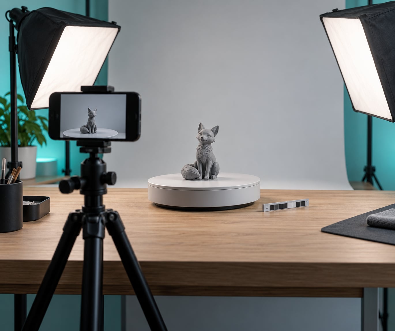
- Light evenly, from two sides. Two soft lights at roughly 45 degrees flatten shadows and reveal surface texture. Harsh single lighting creates shadows the software reads as shape.
- Keep exposure fixed. Auto exposure shifting between frames confuses matching. Lock it where your software allows, or lock the phone.
- Stay sharp. Fix the focus at the object and do not touch the camera between shots. Motion blur in a handful of frames can break the whole alignment.
- Keep the distance similar. Vary it only slightly. A sudden zoom changes the scale the solver assumes.
- Slow the turntable. A plate that completes a rotation in 20 to 30 seconds, with the shutter on a timer or remote, gives consistent spacing.
- Circle at two or three heights. One horizontal ring sees only the equator. Add an elevated and a lowered pass for the top and base.
Watch the live coverage preview if your app has one, and delete frames as you go rather than sorting hundreds of images later.
Before processing, skim the set. Blurry frames, a shot where somebody walked through, a half-finished ring: remove them. Software weights good frames more heavily, but a run of bad ones can drag the alignment.
How Do You Turn the Photos Into a 3D Model?
Import the image set and let the tool match features. Most mobile apps do this in one tap and show a preview within a minute or two, which is the fastest feedback loop in the whole workflow.
Read the sparse point cloud preview carefully. It shows whether the solver has placed the camera positions sensibly. Stretched, doubled or floating clusters in the preview mean the alignment failed, and no amount of downstream processing will rescue it.
If alignment fails, the fix is almost always in the capture rather than the settings. Check for a group of near-identical frames, a background that repeats, or a surface that was too glossy. Then shoot again.
Once alignment holds, generate the dense cloud and inspect the areas you care about. A missing section here is a missing section in the print. Small holes can be repaired later, a whole missing side means another capture session.
Generating the mesh is straightforward. What the tool produces depends on its options, and that matters more than most beginners expect. Ask for a surface rather than a solid, keep the option that removes the background where it exists, and leave decimating until after cleanup, because working at full resolution makes hole filling much easier.
How Do You Make the Scan 3D-Printable?
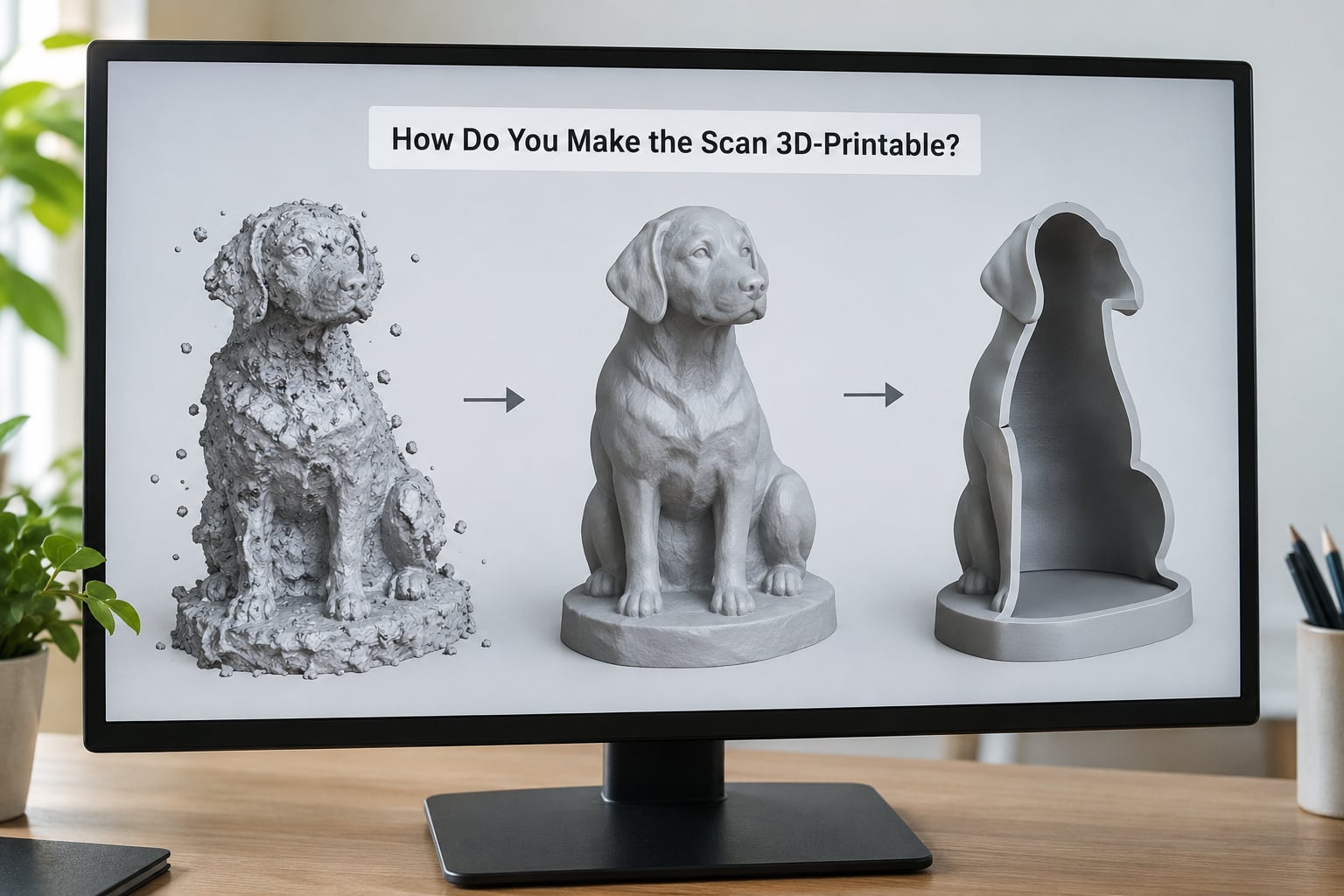
This is the stage that makes or breaks the project. The printability test is short: the model must be watertight, meaning no boundary edges anywhere, and manifold, meaning every edge shared by exactly two faces. Community practice treats those two words as one rule, and it is a good rule.
Work through the repairs in this order.
- Delete stray geometry. Remove the floor plane, the backdrop, and any floating fragments around the object. This is the single biggest time sink, and it is the reason a plain background pays off.
- Select the largest connected component. MeshLab and Meshmixer both have one command for this, and it instantly removes most debris.
- Close the base. Cut the object flat with a plane, or close the bottom with a flat face. Scans rarely end in a clean surface, and a flat base is what stops prints floating above the bed.
- Fill holes. Work from the largest opening down, since a big hole is often the cause of several smaller ones beside it.
- Fix normals and non-manifold edges. Recalculate outward normals, then look for edges touched by three or more faces or by one. Extrude or bridge those boundaries.
- Decimate. Reduce the polygon count to the point where small features are still legible, typically in the low hundreds of thousands for a figurine. Scans of this size often run to millions of triangles, which no slicer enjoys.
- Thicken or shell. Scanned thin sections are often thinner than your nozzle. Solidify the model to at least three times nozzle diameter, or add a shell and infill.
- Scale to millimetres. A scan may arrive in centimetres, metres or arbitrary units. Measure it against the scale marker, or against a known dimension, and scale the whole model to match.
Two repairs are worth naming as a decision rather than a step. Voxel remeshing produces a clean, even, watertight surface but throws away detail, and it is the right call for a part that must fit. Decimation keeps detail and needs more repair. Retopology rebuilds the mesh by hand, which is the professional route and rarely worth it at hobby scale.
Before exporting, slice the file. A five-minute check in your slicer reveals every remaining problem instantly, including the ones no mesh tool reports. Fix what the slicer complains about and slice again.
For orientation, put the largest flat face on the bed and point the finest detail upward. Small overhangs under 45 degrees are fine; steeper ones need supports, and scanned textures love to generate thin, unreachable fragments. A brim helps more than supports on a scan with an uneven base.
How Accurate Is Photogrammetry for 3D Printing?
Accuracy and appearance are different things, and photogrammetry is much better at the second than the first.
On appearance, a good capture reproduces surface detail that a depth sensor or a hobby laser scanner cannot touch, which is exactly why it is the right tool for figurines and organic shapes. On dimensions, expect error in the range of a fraction of a millimetre to a few millimetres depending on rig, object size and how carefully you controlled scale, and treat any number you quote as belonging to those conditions rather than to the method in general.
The usual error sources are predictable. An unknown focal length, a scale marker placed but not measured, a shaky camera, an object warmed or moved between passes, and lens distortion at the frame edges all push the result out. Measuring a known dimension on the finished mesh is the habit worth building.
What photogrammetry is not is metrology. If a replacement part has to slip into an existing assembly with a fixed tolerance, a coordinate measuring machine or a calibrated structured-light scanner will serve you better, and for a simple flat part, tracing two photographs in Fusion 360 may be faster than cleaning up a scan at all.
There is a legal point too, and it comes up often. Scanning an object to make your own copy is a personal use; scanning branded merchandise or a commercial figurine to sell reproductions raises copyright questions. Photography, modelling and printing do not remove the rights of the original designer.
Frequently Asked Questions
Can photogrammetry scans be used directly for 3D printing?
Almost never straight from the scanner. A raw scan usually contains a background plane, holes, open edges and millions of triangles, and a slicer will reject it. You need to delete stray geometry, close the base, fill holes, fix inverted faces and non-manifold edges, decimate, then confirm the mesh is watertight before exporting. Budget 30 to 90 minutes of cleanup for a first scan.
Do you need a turntable to do photogrammetry?
No, a turntable is a convenience rather than a requirement. Hand-holding works if the object stays fixed and you move in small overlapping steps, which is harder than it sounds and often introduces motion blur. A turntable with a phone clamp and a remote or timer shutter makes spacing even and the run repeatable, which usually matters more than the device itself.
How many photos are needed for a 3D scan?
Between 30 and 100 for most objects, and the count matters less than the overlap. Keep consecutive frames 60 to 80 percent overlapped, and split a 360 degree pass into 24 to 40 shots so each surface appears in at least three frames. Small objects let you shoot closer and use fewer frames; large or irregular subjects such as a person need many more and a much higher frame rate.
What is the best phone or camera for photogrammetry?
Any recent phone with a fixed-focus rear camera is genuinely enough for most hobby work, provided you keep the camera still and light the object evenly. A mirrorless or DSLR camera with a 35 to 85 mm lens and a tripod adds the detail and consistency you want for small objects, batches or scanning people. The tripod, the lighting and the matte backdrop affect the result more than the sensor does.
Can photogrammetry scan a person, terrain, or mechanical part?
All three work with different tricks. People and pets need a very still subject and many overlapping frames, which is why multi-camera rigs or a slow walk-around are common. Terrain suits flat overcast light and a scale marker for size. Mechanical parts need light aimed into recesses, and often adhesive targets when a surface is flat, shiny or repetitive.
Why does my photogrammetry model have holes or floating pieces?
Holes usually mean those areas were never seen from two angles, commonly a deep recess, a dark pocket or the underside. Floating pieces are the opposite: the matching stage produced separate fragments, often around a featureless or repeating surface. Fix both at the capture stage with more angles, side lighting and temporary texture, then fill small holes and delete stray components in MeshLab or Meshmixer.
Conclusion
Photogrammetry for 3D printing is a predictable process once you treat it as a pipeline: capture with texture and even light, reconstruct, repair the mesh until it is watertight and manifold, scale it in millimetres, then orient it for the bed. The capture is fast and forgiving. The cleanup is the work, and it is the part worth planning for.
Start smaller than feels sensible. Pick something small, matte and irregular, a painted figurine or a rubber toy, put it on a plain background with a scale marker beside it, and shoot a full ring at 60 to 80 percent overlap before you attempt anything mechanical, anything shiny or anything that moves.