To measure parts accurately with calipers, zero the tool with the jaws closed, open the jaws only as far as the feature needs, keep the measuring faces square and fully seated on flat surfaces with light steady pressure, and read the value before you release. Take the reading three times at different points along the feature. If the numbers disagree, the part is uneven rather than the caliper being wrong.
That is the whole method. Everything else is detail about which jaw to use, how hard to squeeze, and how to tell a real dimensional fault apart from a bad measurement.
This matters more for 3D-printed work than it does for a machined billet, because a printed part has real layer texture, a squashed first layer, and holes that print undersize. A caliper reading is only half the story; the other half is what the printer and material did to that dimension. I check both before I change a slicer setting.
Table of Contents
- 1What You Need
- 2Step-by-Step: How to Measure Parts Accurately With Calipers
- 3Step 1: Choose the Right Caliper Type
- 4Step 2: Clean and Zero the Calipers So You Measure Parts Accurately
- 5Step 3: Measure External Dimensions
- 6Step 4: Measure Holes, Slots, and Internal Features
- 7Step 5: Check Depth and Other Features
- 8Step 6: Verify Accuracy Against the Design
- 9Common Mistakes
- 10Frequently Asked Questions
- 11What can you measure with calipers?
- 12Are digital calipers more accurate than vernier calipers?
- 13How do I zero a digital caliper?
- 14How do I measure the inside diameter of a hole with calipers?
- 15How precise do calipers need to be for 3D printing?
- 16When should I use a micrometer instead of calipers?
- 17Conclusion
What You Need
You need four things, and only one of them is the caliper itself.
- A caliper. A digital caliper with 0.01 mm resolution covers almost all hobby and shop work. Analog vernier or dial calipers are harder to read but they never lose a reading to a dying battery.
- The jaw that matches the feature. Outside jaws for widths, thicknesses and diameters. Inside jaws for holes, slots and bores. The depth probe for recesses and pockets. A step measurement comes from the same jaws, using the flat back of the sliding jaw as a reference.
- A clean measuring surface and a clean tool. Filament fuzz, plaster dust, resin residue and bare fingerprints all sit between the jaw and the part. Wipe the jaw faces with a dry cloth before every reading.
- The design dimensions. A caliper tells you the size of the part. It cannot tell you whether that size is right. Pull up the nominal dimension and the tolerance from your model or drawing before you measure, otherwise you are just collecting numbers.
A small inspection light and a loupe help when you are checking a hole mouth or the edge of a thin wall.
One term matters before you start. Resolution is what the display shows you. Accuracy is how close that display is to the true size. A caliper reading 0.01 mm is only as accurate as the manufacturer says it is, usually around ±0.02 mm, and only if you hold it correctly. Resolution is not accuracy, and for 3D printing the resolution you can afford is rarely the limiting factor.
Step-by-Step: How to Measure Parts Accurately With Calipers
Step 1: Choose the Right Caliper Type
Pick the feature first, then the jaw. Outside jaws measure the thickness of a plate, the width of a printed wall, the outside diameter of a shaft, and the flat-to-flat dimension of a hex nut. Inside jaws measure a bore, the width of a slot, and the inner diameter of a tube. The depth probe measures from the end of the probe to a flat base you rest on the part, which suits counterbores and pockets.
Digital versus analog is a separate choice. A digital caliper gives you a number instantly and holds it when you press the data button, which is easier on the eyes. An analog caliper needs no power, survives being knocked off a bench, and gives you a physical sense of how hard the jaws are closing. For printed parts I use digital for speed and keep an analog one for anything with a tolerance tighter than the layer height.
An example: checking a 6 mm bolt hole in a printed bracket means the inside jaws, and checking the 4 mm shelf thickness on the same bracket means the outside jaws. Using the outside jaws on the hole gives you the wall thickness instead, which is a different dimension.
Step 2: Clean and Zero the Calipers So You Measure Parts Accurately
Wipe both measuring faces and the inside tips. Then close the jaws fully with the thumb wheel, press the zero button on a digital model, and confirm the display reads 0.00. Do that check at the start of every session and again if the tool has been dropped.
Cheap calipers often ship with a zero offset, and a slow zero drift on a digital model is the reason a reading that was 20.00 mm last week is 20.03 mm today. If zeroing leaves the jaws slightly pinched, a hair of plastic or burr is trapped between the faces. Clean again rather than measuring around it.
Step 3: Measure External Dimensions
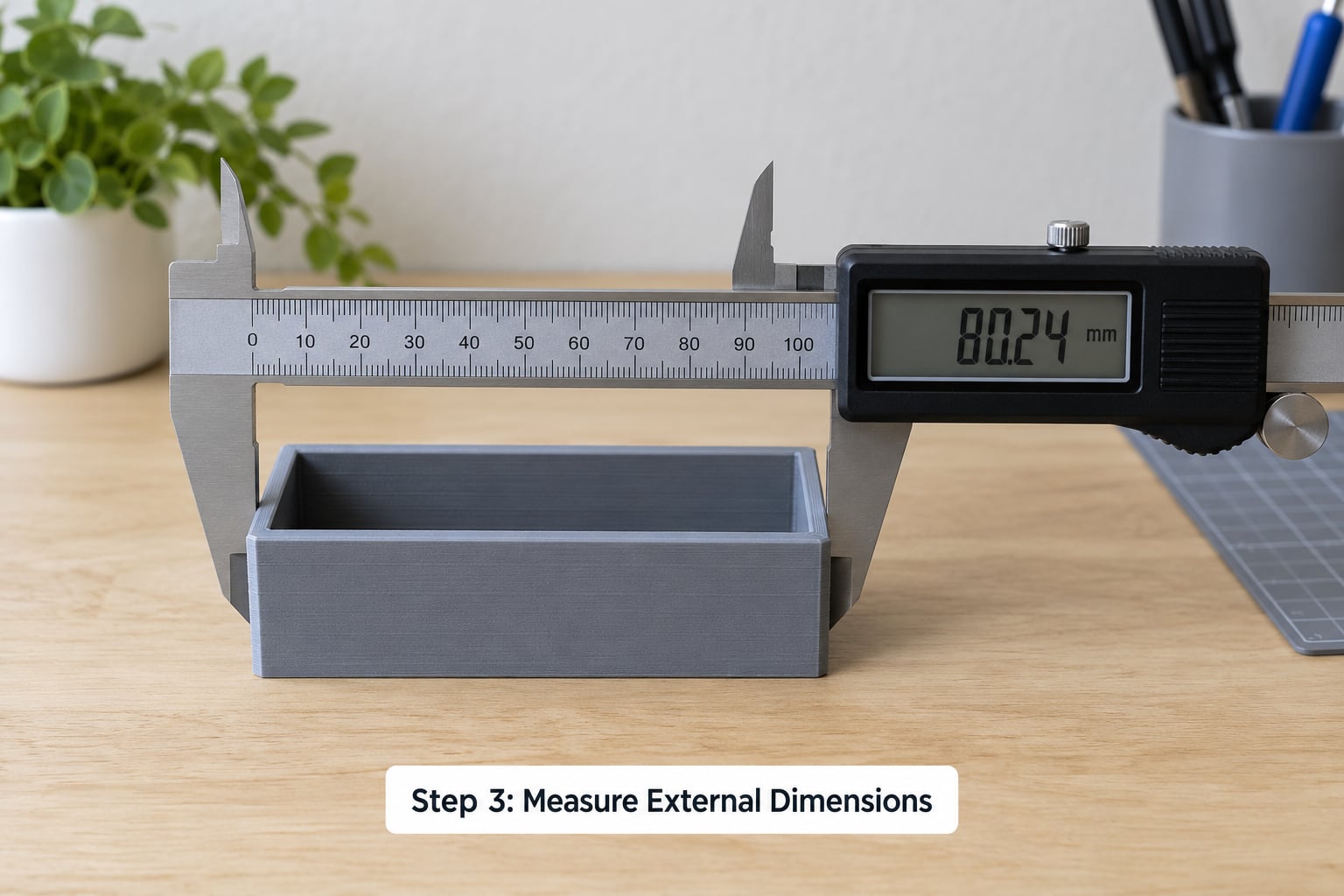
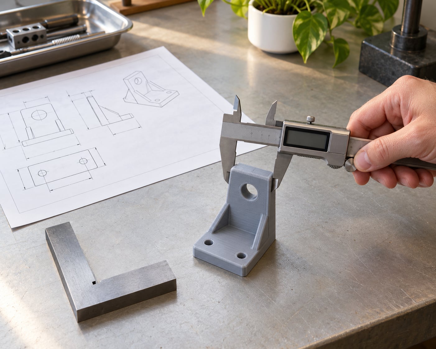
Open the jaws past the part, place the feature between the outside jaws, and close them until both faces touch. The faces must sit flat and parallel on the surface. Rocking the caliper slightly until the reading grows means you were measuring at an angle, and the number you get is too large.
Take three readings at different points along the same dimension. A flat plate that reads 20.00, 20.01 and 20.00 mm is consistent. Readings that climb across the part suggest a warped bed or an elephant-footed first layer, and the caliper is telling you something real.
Step 4: Measure Holes, Slots, and Internal Features
For inside measurement, open the jaws wider than the hole, insert the inside tips, and expand gently until they touch the walls. Never squeeze the tips outward with force. The tips taper, and pushing them sideways deforms the hole and gives you a reading that is too small.
Sweep for the maximum. Keep light outward pressure and rock the caliper through a few positions around the bore. The reading will rise and fall slightly, and the highest value is the true inside diameter. This is the technique people ask about most on machining forums, and it is the difference between measuring a round hole and measuring one unlucky tangent point.
Check the hole at two depths as well. Printed holes usually run slightly undersize because the perimeter path curves inward, and a hole can be correct at the mouth and tight halfway down. For a printed hole that has to take a screw, measure the hole and measure the screw, then decide which one you want to change.
Step 5: Check Depth and Other Features
For depth, lift the depth probe with your fingers, rest the flat back of the sliding jaw on the part surface, and lower the probe until the tip contacts the floor of the recess. Keep the base flat and the probe vertical. A tilted base gives you a shallower reading than the real one, and pressing the probe down compresses anything springy.
For a step measurement, close the jaws on the shoulder and measure the distance from the back of the sliding jaw to the face of the fixed jaw. That figure is the step or shoulder distance, which is not the same as a depth measurement at all.
Check curved and non-uniform features in more than one place. A ribbed surface, a rounded boss and a draft angle all need readings at the top, the middle and the base before you conclude anything.
Step 6: Verify Accuracy Against the Design
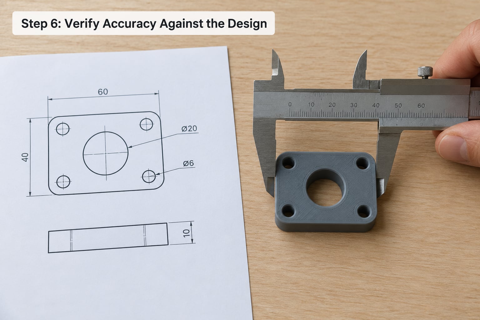
Write down the reading next to the nominal dimension. Then compare it against the tolerance, not against zero. A 6 mm hole specified at 6.0 +0.2 / -0.0 mm that measures 6.15 mm is inside spec, however wrong it feels.
For printed parts, put the print tolerance in the same column as the tool tolerance. A 0.01 mm digital caliper reading 6.12 mm on a hole means the printed hole is about 0.12 mm under nominal, and no caliper technique will take that back. The useful questions are where the deviation appears and whether it repeats, which is why the sweep and the repeat readings matter.
When the deviation is smaller than the tool can resolve, step up to a better instrument. A micrometer handles a thin wall or a shaft to 0.01 mm. A bore gauge measures an existing hole far more accurately than inside jaws. Gauge blocks set a known length to check the caliper against. A height gauge handles tall features a caliper cannot reach.
Common Mistakes
Most bad caliper readings come from a short list of habits.
- Measuring over dust or fuzz. A layer of PET bristle or fingerprint adds straight to the reading. Clean the jaw faces and the part before every measurement.
- Squeezing the jaws hard. Pressure closes the contact area and reads low, and on soft material such as brass or thin printed walls it permanently deforms the part. Light, steady pressure is enough.
- Measuring at an angle. Tilting the jaws makes the reading too large. Seat both faces flat and confirm by gently rocking the caliper: the reading should stop growing.
- Skipping the zero check. A zero offset applies to every reading after it. Close the jaws, look at the display, and zero it.
- Trusting resolution as accuracy. A display that changes every 0.01 mm can still be off by 0.03 mm from the factory, and more if the tool has been dropped.
- Using worn jaws. Blunted or chipped measuring faces give inconsistent results. Close them and look at the contact along the full face, not just at the tips.
- Taking one reading and moving on. Three readings cost seconds and tell you whether the part or the technique is the problem.
- Forgetting the probe is part of the tool. On many calipers the depth rod moves when you press the external jaws. Always return the probe by closing the jaws fully before a depth reading.
One last check: measure the same known-good feature at the start and the end of your session. If the two readings differ, the tool has shifted, not the part.
Frequently Asked Questions
What can you measure with calipers?
A caliper covers four measurement types. Outside jaws give thickness, width, outside diameter, shaft diameter and step-to-face distance. Inside jaws give bore and hole inside diameter and slot width. The depth probe gives pocket, counterbore and recess depth. It cannot measure angles, roughness, thread pitch directly, or anything on a part it cannot physically reach, which is where a height gauge or micrometer takes over.
Are digital calipers more accurate than vernier calipers?
Not by much. A digital caliper is easier to read and usually resolves to 0.01 mm, but its accuracy is set by the manufacturer, typically plus or minus 0.02 mm, and that figure covers the whole range. An analog vernier of good quality is just as accurate in practice. Pick digital for speed and readability, analog for battery-free durability, and judge both by the printed accuracy spec rather than the display.
How do I zero a digital caliper?
Clean the jaws first, then switch the caliper on, close the jaws fully using the thumb wheel, and press the zero button so the display reads 0.00. Leave it closed a moment and confirm the value has not drifted. Zero again whenever you change units or the tool has been knocked. If the jaws will not close completely without pinching, something is trapped between the faces and needs cleaning before you measure.
How do I measure the inside diameter of a hole with calipers?
Open the inside jaws wider than the hole, insert the tips, then expand gently until they touch the walls. Do not squeeze them outward. Keep light outward pressure and rock the caliper through several positions around the bore, taking the highest reading you see. That sweep finds the true maximum inside diameter instead of one unlucky tangent point, and it also reveals a hole that is out of round.
How precise do calipers need to be for 3D printing?
A 0.01 mm digital caliper is plenty for almost all FDM work, because the print itself usually varies by more than that. Most printer owners tune flow and first layer height on readings from tools far coarser than 0.01 mm. Spend the effort on technique and on repeat readings instead. Buying a more expensive caliper changes what you can detect on a well-tuned printer, not the limits of the process.
When should I use a micrometer instead of calipers?
Use a micrometer when you need to resolve a thin wall, a sheet, or a shaft to better than about 0.03 mm, or when you are checking a dimension a caliper jaw cannot seat flat on. Use a bore gauge for an existing hole, gauge blocks to set a known length for checking your caliper, and a height gauge for tall or awkward features. Outside jaws sit on two small patches of surface, which is why they can read slightly large.
Conclusion
Start with the tool, not the part: clean the jaw faces, close the jaws, and confirm the display reads zero. Then measure the feature with the jaw that fits it, seat both faces flat, use light steady pressure, and take the reading three times before you believe it. Comparing that number against the design tolerance tells you whether the part is out or your method is.
Repeat readings are the whole trick. When three readings agree, you can trust the measurement and go look for the fault in the print. When they disagree, you have learned something useful about the part’s shape, and no amount of technique would have shown you that with a single reading.