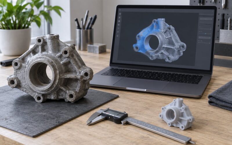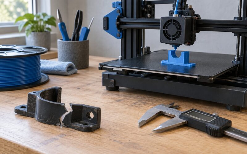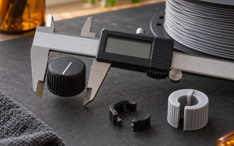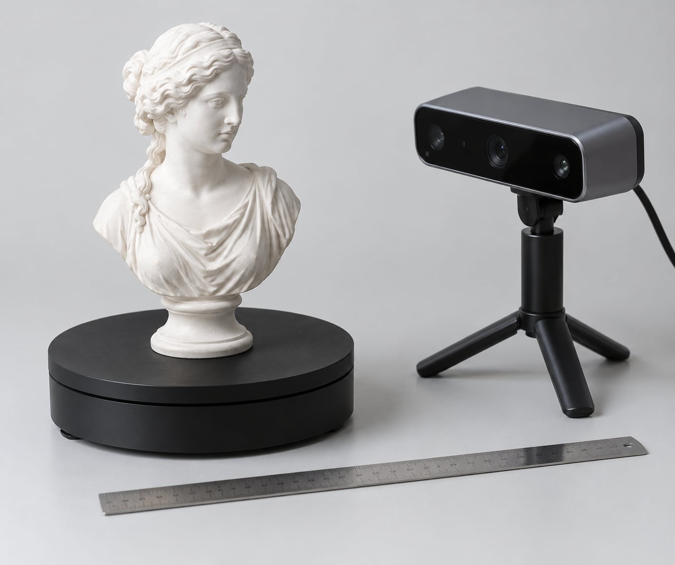
To scan an object for 3D printing, you capture its surface as a digital polygon mesh using one of three methods: photogrammetry from many overlapping photos, a dedicated scanner using structured light or a laser, or a phone or tablet app that does the work for you. Once the mesh exists, you repair the damage, confirm it matches real-world scale, and export it as a file your slicer can read. A small tabletop object takes roughly 20 minutes of capture and about the same again for cleanup.
This guide walks the whole path, from preparing the object to exporting a test file. It assumes no particular brand, operating system or printer, because the workflow is the same everywhere and only the menu names change.
Table of Contents
- 1What You Need
- 2How to Scan an Object for 3D Printing: Step-by-Step
- 31. Inspect and Prepare the Object
- 42. Choose and Set Up a Scanning Method
- 53. Scan an Object for 3D Printing From Every Side
- 64. Process the Scan Into a Digital Mesh
- 75. Repair Holes, Noise, and Problem Areas
- 86. Check Scale, Wall Thickness, and Printability
- 97. Export an STL, 3MF, or OBJ File
- 10Common Mistakes
- 11Frequently Asked Questions
- 12Can I scan an object for 3D printing with a phone?
- 13What file format should I export for 3D printing?
- 14How do you scan shiny or reflective objects?
- 15What scan resolution do I need for accurate 3D printing?
- 16Should a 3D scan be watertight before printing?
- 17Conclusion
What You Need
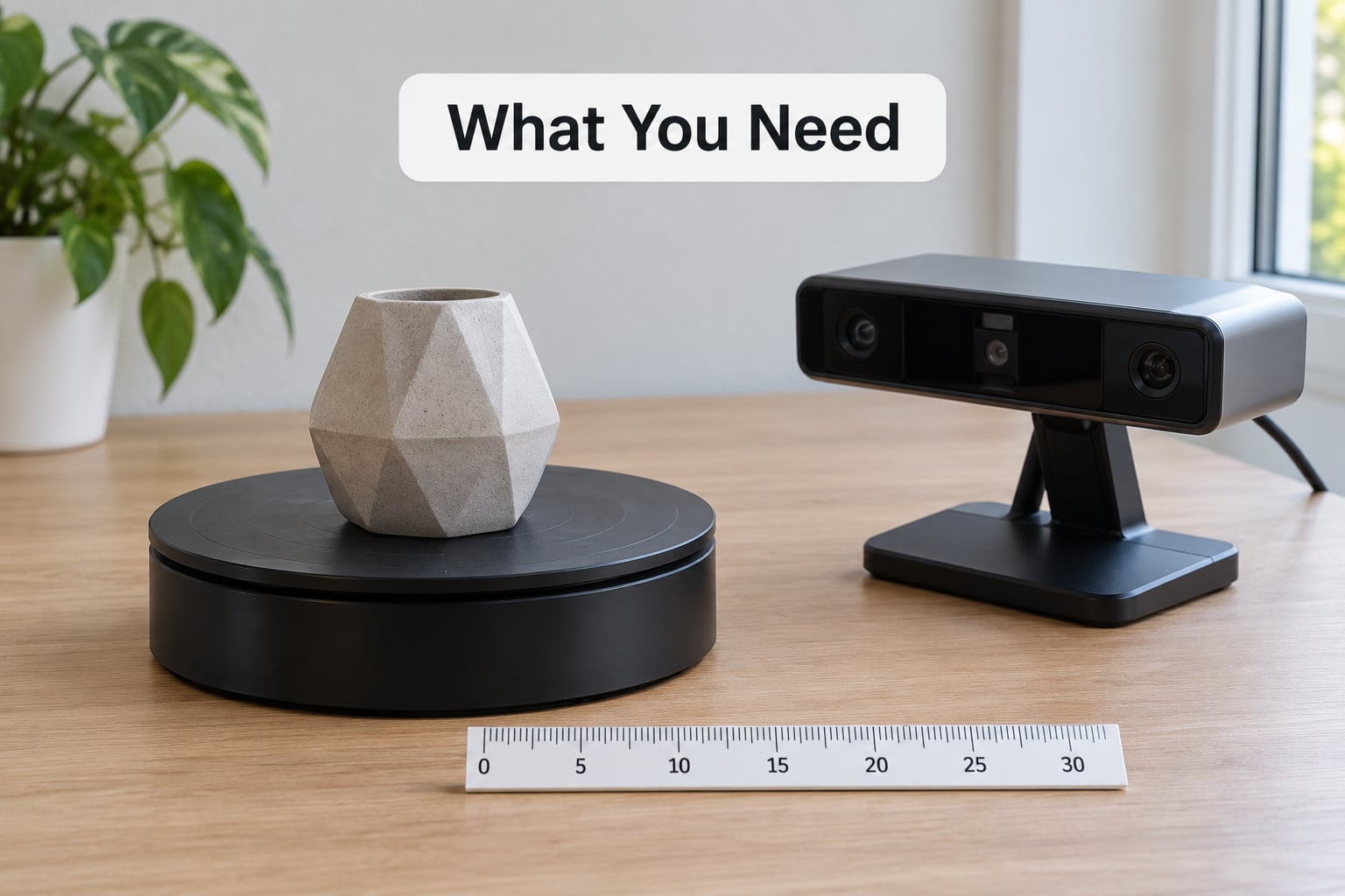
Eight things matter, and the list is shorter than most people expect. You need the object itself, a capture method, a support to hold or rotate it, controlled lighting, a computer, scanning software, a mesh editor, and a known measurement to calibrate scale against.
- The object. Small, rigid, opaque and non-reflective items scan most reliably. A ceramic mug will fight you; a matte plaster figurine will not.
- A capture method. This is either a phone or camera running a photogrammetry app, a structured-light desktop scanner, or a handheld laser scanner. More on the choice below.
- A support. A turntable, a lazy Susan, a rotating platform or a non-slip mat. If the object shifts by even a millimetre mid-capture, the alignment step will fail.
- Lighting. Two soft, diffused sources at 45 degrees beat one bright lamp. Avoid direct overhead light, which flattens every surface into the same brightness and hides shape.
- A computer. Photogrammetry processing is heavy. 16 GB of RAM is a practical floor for anything but the smallest objects, and a dedicated graphics card helps a great deal with the alignment stage.
- Scanning software. Photogrammetry options include KIRI Engine, RealityCapture, Polycam and Metashape. Desktop scanner packages usually bundle their own.
- A mesh editor. Blender and MeshLab cover repair at no cost, and both handle scale and export as well as anything you would pay for.
- A scale reference. A steel rule, a caliper, or a printed checkerboard target placed in frame. Without one you are guessing at real-world size.
Scanning spray is the item most people forget. A light dusting of matte scanning spray or even plain talcum powder kills reflections on glossy plastic, chrome and dark surfaces, and it is the difference between a usable scan and a ruined one.
How to Scan an Object for 3D Printing: Step-by-Step
Seven steps take you from a dusty object on a table to a file your slicer accepts. The order matters: cleaning early saves repair work later, and scale checking before export prevents a wasted print.
1. Inspect and Prepare the Object
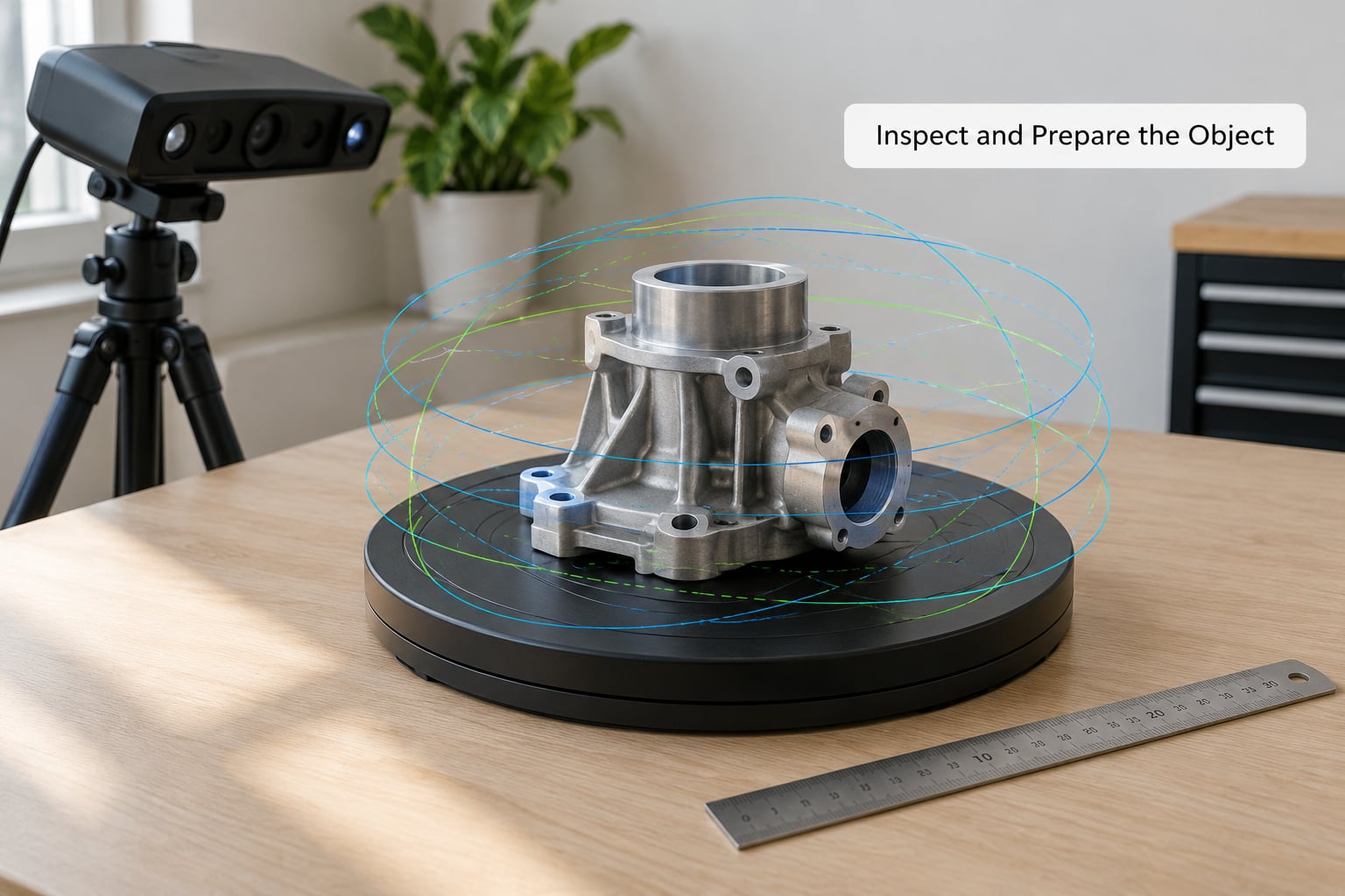
Start by deciding what actually needs capturing. Loose parts, stuck-on labels and rubber feet either come off or get masked out, because anything that can move between frames will break registration. Clean the surface with a dry cloth and a little isopropyl alcohol to remove fingerprints and oils, then fill or seal deep holes with filler putty if they are smaller than a few millimetres.
Give the object a matte, contrasting background. A sheet of plain black or white card behind it stops the software trying to model the table as part of the object, and a matte surface gives the capture something to track.
It works if the object sits still, stays fully visible, and has surface texture for the method you picked. A completely smooth white surface will fail with photogrammetry no matter how careful your photographs are.
2. Choose and Set Up a Scanning Method
Pick the method by object size, accuracy needs, surface type and how much time you want to spend. Structured-light scanners project a pattern of light and read the distortion, which suits opaque matte objects up to roughly shoe size and needs only one pass. Laser scanners sweep a line and triangulate, handling shiny or dark surfaces better and covering larger items, at the cost of higher outlay and a fixed working distance of about 40 to 50 cm.
Photogrammetry uses a phone or camera and overlapping photographs. It costs nothing extra, handles objects far larger than a scanner can, and produces a textured model, but it needs good lighting, a matte surface and real skill with the camera. LiDAR apps on recent phones and tablets produce a rough mesh in seconds for face and body scans, and they struggle with anything smaller than about 10 cm because the depth sensor has too little surface to read.
On a phone, a quick object scan app captures a small figurine in about two minutes, and a dedicated desktop scanner or laser unit fits a mechanical part where you need known dimensions. Photogrammetry sits between the two, and it is the only one of the three that records colour and texture.
For setup, put the scale reference in frame before you start, lock the phone or camera exposure, focus and white balance, then turn off every automatic setting. With a desktop scanner, calibrate it against its own calibration board first, and set the working distance to where the object fills most of the frame. Software interfaces differ by device and version, so treat any specific button label as a hint rather than a requirement.
3. Scan an Object for 3D Printing From Every Side
Capture coverage is where most first scans fail. For photogrammetry, work through a fixed protocol: shoot a full 360-degree ring at eye level to the object, then add 4 to 5 more rings at different heights, including one looking straight down and one looking up from below.
Every surface should appear in at least 3 separate photos, with 60 to 80 percent overlap between neighbours. Keep the same distance and angle on every shot, and keep the object itself completely still while you move. Practically, that means turning the turntable rather than walking around the table.
Watch out for surfaces that produce no usable data: mirrors, glass, polished chrome and anything translucent. Also cover thin fins, deep recesses and overhangs, since scanners and cameras both lose detail there. Move closer for small features rather than relying on digital zoom, and check the live preview often if your software provides one.
For a desktop scanner, the rule is simpler: sweep every face in overlapping passes at a steady walking pace, and re-cover any band that the preview shows as sparse. Community practitioners put a laser scanner’s optimal feature-tracking distance at roughly 40 to 50 cm, which is close to where most units are calibrated.
You have enough data when every angle has at least three views, the base and the underside are covered, and the preview shows no gaps on the object itself.
4. Process the Scan Into a Digital Mesh
Processing turns raw captures into one usable surface. Alignment matches every photo to the others and rejects ones that do not fit, then depth estimation builds dense point data, and finally meshing converts those points into connected triangles.
Crop away anything that is not your object: the turntable, the card background, your hands and the ruler if it was captured in close. Choosing a surface orientation sets which face counts as the bottom, which decides whether your part prints upright or on its side.
The test is simple. Look at the model in wireframe or shaded mode and check that it reads as one continuous shape rather than a pile of fragments. If pieces float near the main body or the surface has torn open, the capture missed data and you should go back and shoot more rather than trying to repair a gap that was never covered.
5. Repair Holes, Noise, and Problem Areas
Scans arrive with predictable defects: small holes where no camera saw the surface, stray floating geometry from the background, bumpy noise on curved areas, and duplicate or overlapping surfaces at the seams.
In Blender, the useful sequence is short. Select all by trait, choose loose parts, and delete the floating debris. Use merge by distance to weld duplicate vertices sitting on top of each other, then fill small holes. Recalculate outside normals so lighting and slicing both read the surface correctly, and finish with a light smoothing pass set to a low factor.
Watch the smoothing strength. Turn it up and you erase exactly the detail you scanned for, including engraved lettering, which is the single most common complaint from first-time users. Repair the geometry that affects printing by hand where you can, and use automated repair with a known thickness only for scattered pinholes.
The model is ready when it behaves as a solid: no visible openings, no inverted shading, no interior walls, and nothing floating outside the body.
6. Check Scale, Wall Thickness, and Printability
Scale is the step people skip, and it is the step that turns a good scan into a print at the wrong size. Most photogrammetry software imports at an arbitrary scale, so set the units to millimetres, measure one known feature of your model with the software’s measure tool, compare it against the real object, and apply a single uniform scale factor to the whole model.
Then check the features the printing process cares about. FDM printers generally need walls around 0.8 to 1.2 mm to be reliable, resin printers can hold thinner walls near 0.4 mm, and powder bed processes print solid parts with no supports at all.
Look for unsupported overhangs, cavities that will trap uncured resin or powder, and moving parts with no clearance. A pair of mating halves usually needs about 0.2 to 0.3 mm of gap so they do not fuse together on the build plate.
Before committing material, run the file through your slicer and read the preview. If the slicer reports no errors and the layer view looks right, take a small test print or a slice preview at a reduced height first.
7. Export an STL, 3MF, or OBJ File
STL is the universal fallback and the right choice for single-colour FDM or resin prints, since almost every slicer reads it. It stores geometry only, so scale depends entirely on what you set before exporting.
OBJ carries a texture map, which makes it the right pick when you want colour on a full-colour printer or want to keep a reference of the original surface. 3MF is the modern option and the one I default to for anything with multiple parts, embedded units, or colour information, since it holds those attributes in one file instead of splitting them across several.
Set the export unit to millimetres, export, then reopen the file in a fresh session. If the reopened model matches your intended dimensions and your parts are still separate objects, the export is clean. Skipping that reopen step is how a lot of people discover a unit mismatch only after a nine-hour print.
Common Mistakes
Almost every failed scan traces back to one of a handful of problems, and each has a direct fix.
- Harsh or uneven lighting. Strong shadows and hotspots give the software false edges. Fix it with two diffused sources at 45 degrees and a matte background.
- A surface with no texture. Smooth white plastic gives nothing to track. Fix it with matte scanning spray, talcum powder, or a thin removable texture coat.
- Skipped angles. Gaps in the base or under an overhang become permanent holes. Fix it by adding the top-down and bottom-up rings and confirming three views per surface.
- Wrong scale. The model imports at an arbitrary size. Fix it by measuring a known feature and applying a uniform scale factor before export.
- Disconnected meshes. Separate fragments usually mean the object moved between frames. Fix it by using a turntable and checking the preview before processing.
- Unrepaired holes. Small pinholes cause slicer errors and internal resin traps. Fix it by filling holes after noise removal, not before.
- Excessive smoothing. Engraved lettering and fine texture disappear. Fix it by keeping the smoothing factor low and repairing by hand near detail you care about.
- Wrong export units. A millimetre model exported as centimetres prints 10 times too big. Fix it by setting units explicitly and reopening the file to confirm.
- Over-thick walls. A scanned shell can carry far more material than needed. Fix it by checking wall thickness against your process minimum and hollowing the model where a solid section adds nothing.
A few quality-control habits catch problems early: check the mesh in wireframe before exporting, run the analysis tool inside your mesh editor, and keep your source project file so you can reprocess without recapturing.
Frequently Asked Questions
Can I scan an object for 3D printing with a phone?
Yes, for most small objects. A photogrammetry app turns 40 to 80 overlapping photos into a mesh, and apps using the phone’s LiDAR sensor produce a rough model in seconds. Expect roughly 1 to 2 mm of accuracy on a 10 cm object, which suits figurines and decorative pieces but not precision parts. Give the surface matte spray first, keep the lights even, and you will avoid most failures.
What file format should I export for 3D printing?
Use 3MF for most work because it stores millimetres, colour and multiple parts in a single file. STL is the safest fallback for single-colour FDM and resin prints, since every slicer reads it, but it carries geometry only and relies on the scale you set. Choose OBJ when you want to keep the scanned texture map alongside the geometry.
How do you scan shiny or reflective objects?
Coat them. Reflections confuse both cameras and structured light, so apply a thin layer of matte scanning spray or dust talcum powder over the surface and let it settle before capturing. For black or dark plastic, the opposite problem appears: the surface absorbs light and returns almost nothing, so raise exposure or add a bright, even light. Transparent items need a removable matte coat and a solid backing behind them.
What scan resolution do I need for accurate 3D printing?
Match detail to the smallest feature you care about, not to the object size. A 100 mm figurine captured with roughly 0.1 mm spacing holds up for FDM printing, while a replacement mechanical part needs closer to 0.02 mm to preserve clearances and threads. More resolution means more photos, a longer processing time and a heavier file, so extra detail beyond your printer’s own limit rarely helps.
Should a 3D scan be watertight before printing?
Yes, for solid printing processes such as FDM and resin. A watertight mesh has no holes and no free edges, so the slicer can generate reliable walls and fill the interior. Powder bed processes such as SLS and MJF need less, since the powder supports the part. Test by running the analysis tool in your mesh editor; any reported boundary edges mean the model is not yet watertight.
Conclusion
Start with preparation, because a clean matte object on a still turntable is worth more than any software setting. Capture complete overlapping data with a full 360-degree ring, 4 to 5 elevation heights and at least three views of every surface, then repair the mesh and check that it reads as one solid shape. Confirm real-world scale against a measured feature before you export, and send a small test file to your slicer first. That sequence turns an unpredictable afternoon of guesswork into a repeatable process you can repeat on the next object.