Z wobble artifacts are repeating horizontal ridges that show up on the vertical walls of a print because the Z axis shifts sideways as it rises. Almost always the source is mechanical: a bent or misaligned lead screw, a loose fastener, an over-constrained gantry or a worn nut. To reduce z wobble artifacts, you diagnose the band spacing first, then work down the axis from frame to coupler to lead screw, changing one thing at a time. Most printers come back clean in under an hour.
Before you take anything apart, print something small and repeatable. A vase-mode spiral tower or a simple calibration cube gives you flat, uninterrupted vertical walls in about fifteen minutes, and it is the only way to know whether a change actually helped.
If your printer is new to you or you are still choosing hardware, it helps to know what the machine’s motion system is made of before you start reading menus — printing technique basics cover the differences between Cartesian, CoreXY and belt-driven Z layouts that shape which fix applies to you.
Table of Contents
- 1What You Need
- 2How to Reduce Z Wobble Artifacts: Step-by-Step Fixes
- 31. Learn How to Reduce Z Wobble Artifacts by Diagnosing the Cause
- 42. Check the Printer Frame and Gantry for Movement
- 53. Inspect and Correct Z Belts
- 64. Verify Lead Screws, Nuts, and Vertical Alignment
- 75. Remove Mechanical Interference and Improve Motion
- 86. Calibrate Z Steps, Bed Leveling, and Mesh or Trimesh
- 97. Reduce Vibration and Check Firmware Settings
- 108. Tune Print Parameters and Verify With a Test Print
- 11Common Z Wobble Mistakes
- 12A Clean Test Print Showing Z-Layer Consistency
- 13Inspecting Z-Axis Motion Hardware
- 14Common Mistakes
- 15Frequently Asked Questions
- 16What causes Z wobble artifacts in a 3D printer?
- 17Should I increase Z-axis tension to fix wobble?
- 18How do I know if my Z belts or lead screws are causing the problem?
- 19Can Z wobble be fixed through firmware or slicer settings?
- 20Do resin printers and FDM printers fix Z wobble differently?
- 21When should I replace a Z belt, lead screw, or Z-nut?
- 22Conclusion
What You Need
Nothing here is exotic, and you can do the whole procedure with what most printers ship with.
- Printer manual — for your exact model, because Z hardware positions and firmware menu names differ between Ender 3, CR-10, Neptune, Bambu Lab, Creality K1 and Voron style machines.
- Metric hex keys — usually 2 mm, 2.5 mm and 3 mm cover frame, gantry and motor mounts.
- Digital calipers or a steel rule — to measure band spacing on the print. This is the single most useful tool in the whole job.
- A flat surface and a straightedge — a glass table or granite tile for the lead screw roll test, and a long straightedge for checking gantry level.
- Clean lint-free wipes and a brush — plus a degreaser such as isopropyl alcohol to clean linear rods.
- Lubricant appropriate to the part — a PTFE-based oil or a dry MoS2 lubricant for lead screws and the Z nut.
- Replacement parts if diagnosis calls for them — a T8 lead screw, an anti-backlash nut, a Z belt or a flexible coupler.
- Access to motion and firmware settings — Marlin, Klipper and stock firmware all expose Z speed, Z acceleration and stepper current somewhere.
Power the printer off and unplug it before touching motors, couplers or lead screws. Move the Z axis by hand before powering it back on so nothing is driven into a bind.
How to Reduce Z Wobble Artifacts: Step-by-Step Fixes
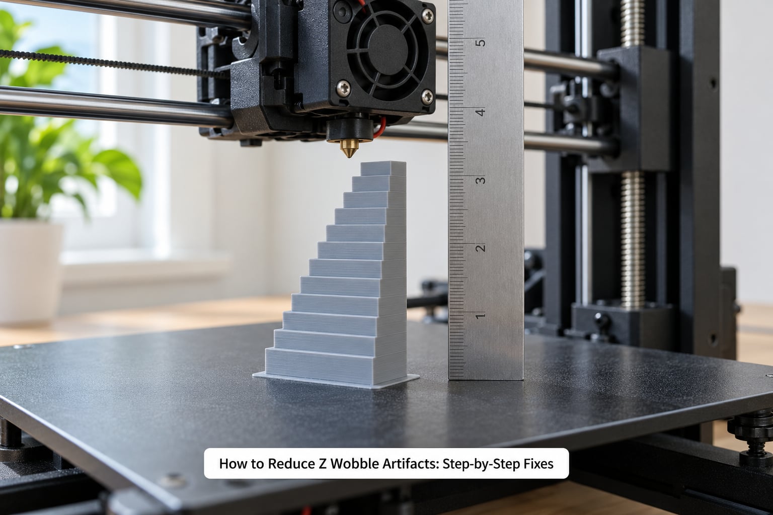
1. Learn How to Reduce Z Wobble Artifacts by Diagnosing the Cause
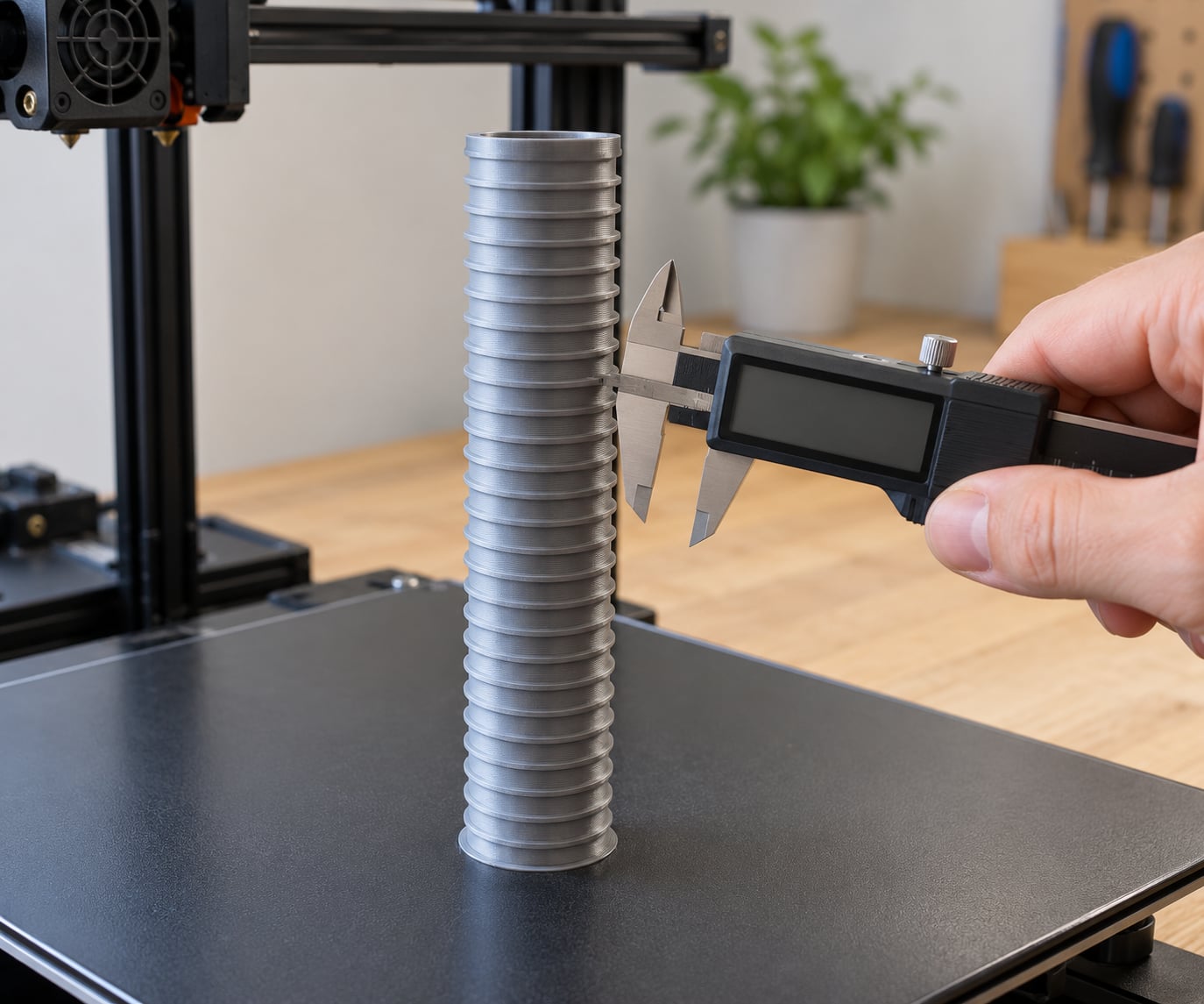
Z wobble, also called z banding when the cause is per-layer inconsistency, looks like a stack of shallow horizontal grooves on flat vertical walls. The defining clue is the spacing between the bands, and measuring it tells you which part of the machine to blame.
Take a calipers, measure a distance of about 40 mm along the wall, count the ridges inside that span, and divide. A standard T8 lead screw has an 8 mm pitch, so genuine wobble repeats every 8 mm and often shifts phase as height changes. Roughly one layer height of spacing points at layer-by-layer inconsistency instead. A wider, slower cycle that matches your hotend’s warm-up behaviour points at thermal effects, and irregular or randomly spaced bands point at binding or a stepper that is skipping.
Rule out the look-alikes before you start. A layer shift is a sudden jump of the whole print, not a repeating pattern. Under-extrusion looks like gaps and stringing rather than regular ribs. Ringing is a wave pattern on the surface of curved walls that follows infill lines, not horizontal bands. And the diving board effect is a visible tilt of tall thin parts caused by frame flex, which is a rigidity problem rather than a wobble problem.
Then print the same tower, at the same temperature, with the same filament. A repeatable artifact gives you a signal worth trusting.
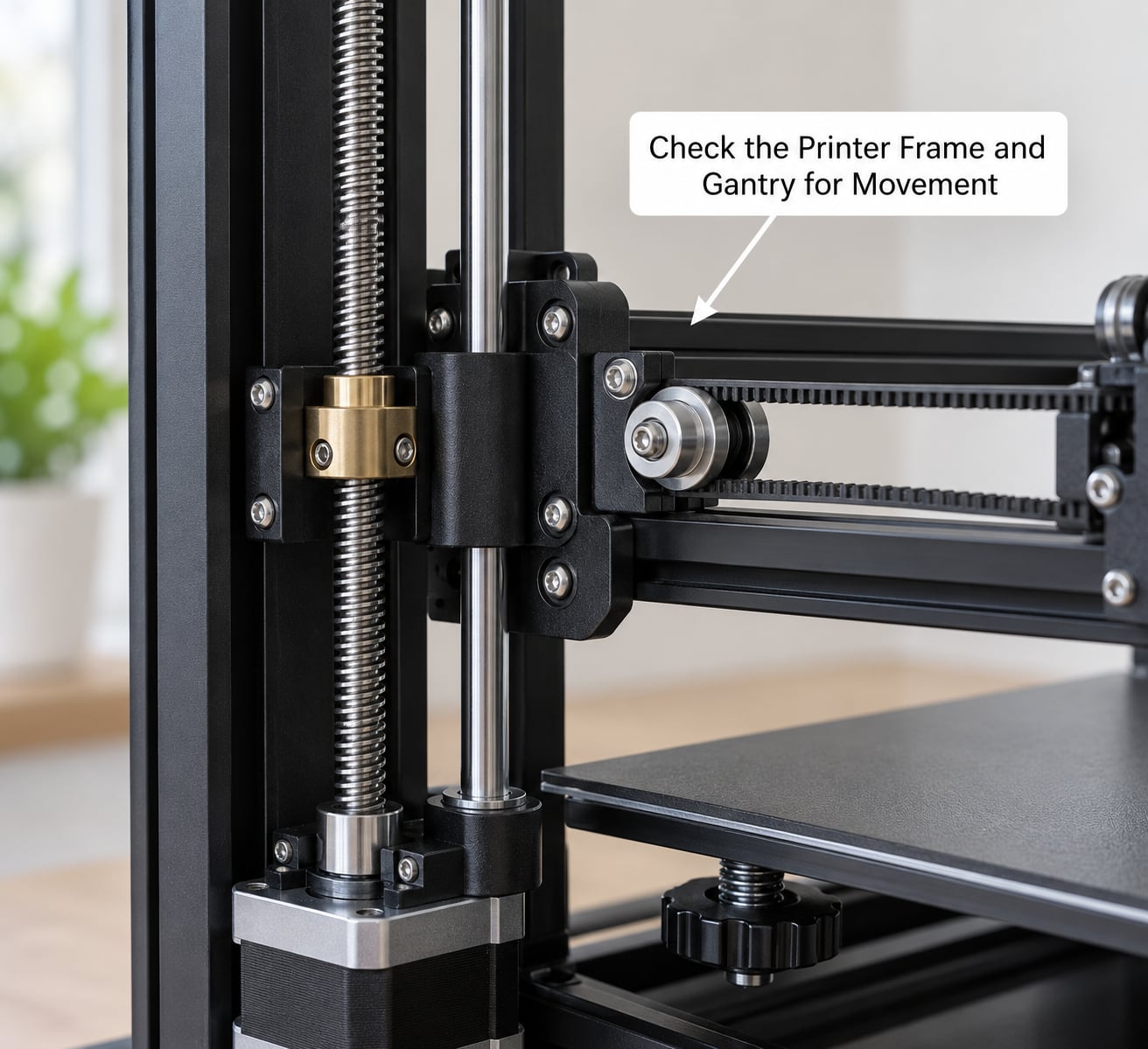
2. Check the Printer Frame and Gantry for Movement
Loose fasteners are the highest-yield fix in practice. The most-upvoted repair thread on r/FixMyPrint was four loose screws where the lead screw mounts meet the X carriage, tightened, and the artifact disappeared entirely. Check there first, every time.
Work through the Z-related fasteners with a hex key: both lead screw mounts, the Z motor mount, the top bearing blocks, the X gantry extrusions and the frame corners on that end of the machine. Turn the printer on its side and look for frame ends that flex when you press on them; acrylic frames move far more than aluminium or steel ones.
Use the move-then-tighten order that experienced builders follow. Loosen the trapezoidal nut, the Z motor and Z top mount screws, move the axis up and down by hand so it settles naturally, then tighten in that order. Forcing the axis into position while everything is already clamped is exactly what creates the side load that causes wobble.
Run the isolation test if bands persist. The Prusa forum’s accepted method is to remove the X axis completely so the Z rods and lead screws hang free, then move Z in 100 mm increments and watch whether the screw stays centred or leans to one side. Deviation with the gantry removed points at a bent lead screw; clean, centred motion points at the gantry mounts instead.
3. Inspect and Correct Z Belts
On belt-driven printers, including most Bambu Lab, Neptune and Prusa-style machines, the belt does not set Z position but it does set how smoothly the axis travels. Frayed teeth, a belt that rides off the pulley tooth crest, or a pulley sitting at an angle will all produce a repeating vertical disturbance.
Check that every tooth lands on the pulley correctly by rotating the axis by hand and watching the belt through its whole travel. Clean the teeth and pulleys with a brush and isopropyl alcohol; a black belt leaves a residue that makes a jumpy axis worse.
Tension is a balance, not a maximum. Too loose and the axis can lag under acceleration, too tight and the belt, bearings and frame take side load that shows up as wobble. Follow the printer manufacturer’s tension procedure, or apply a firm but not extreme deflection, and make sure the Z motor pulley is square to its mount before you change anything else. Replace a belt whose teeth look rounded, cracked or shiny. Do not stack washers or stretch the belt past its rated width to add tension.
4. Verify Lead Screws, Nuts, and Vertical Alignment
The roll test takes thirty seconds. Set the lead screw on a flat glass or granite surface and roll it end to end. A straight screw sits still or rolls uniformly; a bent one rocks and bobs, usually worst in the middle of its length. That centre rock is what produces the classic 8 mm band cycle.
A bent T8 screw is rarely worth straightening. Replace it, support both ends properly, and make sure it is not clamped so hard between the motor shaft and the bearing that it has to flex to turn.
Next, look at the nut. A brass trapezoidal nut develops play, and free play becomes visible surface variation. An anti-backlash nut, typically POM or Delrin, splits the nut into two sections that push against each other and remove the backlash gap. The trade-off is friction: the split nut is tighter, so it takes more stepper torque and can raise stepper temperature. Check your manufacturer’s current settings rather than cranking them blind.
Lubricate the screw and nut with a PTFE-based oil or a dry MoS2 lubricant every 200 to 300 hours of printing. Never use grease on a lead screw; it collects dust and turns into a grinding paste that wears the nut faster than dry running does.
Finally, check vertical alignment. The two lead screws on a dual-screw machine should run parallel, and the same applies to the pair of linear rods supporting the gantry. Place a straightedge across the gantry at the front and rear and compare gaps at both ends. Adjust the Z motor position until both screws follow the gantry evenly.
5. Remove Mechanical Interference and Improve Motion
Anything touching the moving axis adds a force the machine was never designed to absorb. Bundle zip ties, a bowden tube loop that catches on the gantry, a fan duct that rubs the bed, a cable chain that goes taut at one end of travel, and a sheet-metal or acrylic cover that the bed hits at full Z.
Pay special attention to a spool holder mounted on top of the frame. Users have traced real wobble to a heavy spool tugging the filament path and jerking the Z axis mid-layer. Moving the spool off the frame or fitting a printed parametric holder with 608 bearings and a copper top guide removes that disturbance.
Clean the linear rods while you are there. Ultimaker community members resolved minor but consistent Z artifacts by cleaning dirty rods with degreaser and a toothbrush and drying them fully. Wipe the rods and the lead screws in the direction of travel, and re-run the isolation test afterwards to see whether the axis feels lighter.
6. Calibrate Z Steps, Bed Leveling, and Mesh or Trimesh
Once the hardware moves cleanly, the firmware needs to agree with it. Run the printer’s Z steps calibration so a commanded 100 mm really moves 100 mm, then home the axis and repeat. A wrong Z step size does not create wobble, but it changes layer height and makes the calibration unreliable.
Level the bed properly, then run mesh or Trimesh bed levelling if your machine has it. A mesh that drifts across the bed makes the nozzle height change as it travels, which looks like a surface defect on tall walls and gets mistaken for wobble. On dual-screw machines, G34 or its equivalent does this automatically; run it before every print if the firmware supports it.
Menu names and procedures differ by printer and firmware. Marlin, Klipper and stock firmware each put these tools in different places, so follow the documentation for the firmware you actually run rather than a generic guide. If a Y-splitter ties two Z motors together, confirm they are configured as one synchronized Z axis; two motors fighting each other cause a slow, irregular version of the same artifact.
7. Reduce Vibration and Check Firmware Settings
Z motion has almost no load, so it should be gentle. Start with Z speed around 5 to 8 mm/s and Z acceleration near 100 mm/s² in Marlin’s M204 terms, then raise them only if bands stay unchanged. Jerky Z acceleration transmits shock up into the frame and can turn a slightly loose gantry into visible banding.
Check stepper current too. Too little current and the Z motor skips under load, producing an irregular artifact that looks random but is mechanical. Too much and the motor runs hot enough to smell; the practical ceiling most builders use is a motor you would not want to hold for a full minute. Use your firmware’s current or Vref procedure rather than guessing, and remember the Vref figure only applies to the driver your board uses.
If your firmware supports input shaping or filtering, it smooths motion-induced ringing but does nothing for a bent screw. Make sure firmware and input shaping settings match your printer model and your actual hardware, because a mismatched profile can make Z moves worse rather than better.
8. Tune Print Parameters and Verify With a Test Print
Slicer settings cannot fix a bent lead screw, but they change how visible the artifact is and can reveal what you are dealing with. Layer height sets the per-layer band spacing, so a taller layer makes per-layer banding more obvious while leaving 8 mm wobble unchanged. Calibrated E-steps and flow rate stop under-extrusion from adding its own horizontal lines, and Z-hop settings only matter if your nozzle is dragging on the print.
Temperature matters too. Run PID autotune and hold a stable hotend temperature, because cooling swings change the layer line and can read as banding. Dry filament before blaming hardware; moisture affects extrusion, and a filament dryer with desiccant is cheap compared with a weekend of swapping parts.
One more contributor worth knowing: infill telegraphing. On the Bambu Lab forum, users reduced visible micro-banding by lowering infill overlap and adding a third wall so the infill stops printing through the outer surface.
Now print the verification tower. Compare it side by side with the one you made before touching anything, at the same height, under the same light. Even spacing and no repeating wave means the fix worked. Measure the wall with calipers: if the number changed but the surface still looks ridged, the artifact is optical rather than dimensional, which is normal on white or light filament and much less serious than it looks.
Common Z Wobble Mistakes
Most lost weekends come from the same handful of moves. You retension a belt while the frame is out of square. You crank a mount bolt tight without first letting the axis settle, which pre-loads the screw into a bow. You change layer height, flow rate, temperature and Z speed in one session, so when the artifact changes you cannot tell which change did it. You spend an hour calibrating E-steps against what turned out to be a 6 mm bend in a lead screw. And you replace a belt, a coupler and an extruder before ever measuring the band spacing, which would have told you in a minute that the cycle length matched lead screw pitch.
A Clean Test Print Showing Z-Layer Consistency
A finished fix looks boring, which is the point. Photograph or inspect the tower from the side and from above: layer lines run straight and evenly spaced, there is no horizontal wave, and no repeating diagonal pattern anywhere along the wall. Measure ten layers at three heights and they should match within the printer’s own repeatability.
Inspecting Z-Axis Motion Hardware
Before adjustment, lay the axis out so every part is visible at once: lead screw, smooth rod, belt path, pulleys and the gantry mounts. Look for the single contamination smudge, the one mount with a bright witness mark, or the pulley that sits at a visible angle to its shaft. One obvious fault beats an hour of speculative tightening.
Common Mistakes
Here are the errors I see most often, each with the direct correction.
- Tightening before moving. Loosen the nut, Z motor and Z top, move the axis by hand, then tighten. Pre-loaded mounts bend the lead screw.
- Overtightening every fastener. Snug and even beats maximally tight. Over-torqued mounts add the side load they were meant to remove.
- Changing several variables at once. One adjustment, one test print, one conclusion. Otherwise you learn nothing.
- Greasing the lead screw. Use PTFE oil or a dry MoS2 lubricant instead, and keep grease off linear rods and rails.
- Masking with slicer settings. Dropping flow to hide banding produces brittle prints with infill gaps. Fix the hardware.
- Skipping the repeatability test. One clean print proves very little. Run the same tower twice before you call it fixed.
- Skipping the maintenance log. Write down what you changed and the date. The next fault is usually related to the last one.
A light monthly routine prevents most of this: clean the rods and lead screw, check the mounts with a hex key, and check belt tooth engagement. Quarterly, re-run the isolation test and the mesh levelling. If your frame is acrylic, add a brace or move to aluminium before chasing anything else.
If you have not already, it is worth skimming our guides to post-processing and surface finishing so you know what a print can still achieve, and to printing materials when choosing filament for light-colour parts where any surface variation shows.
Frequently Asked Questions
What causes Z wobble artifacts in a 3D printer?
Z wobble artifacts are horizontal ribs on vertical walls caused by the Z axis moving sideways as it rises. The usual culprits are a bent or over-constrained lead screw, loose carriage or motor mount screws, a misaligned X gantry, a worn brass nut with backlash, dirty linear rods, or a motor skipping under insufficient current. Measuring the band spacing separates these causes: 8 mm spacing means lead screw pitch, one layer height means per-layer inconsistency.
Should I increase Z-axis tension to fix wobble?
Only on belt-driven Z systems, and only if the axis lags or the belt visibly slips. Most Z wobble comes from the lead screw, couplers and gantry mounts, not from a loose belt. Tensioning a lead screw or tightening Z mounts harder makes the problem worse by adding side load to the screw. Start with fasteners at the correct snugness, then tension belts only where the manufacturer specifies it.
How do I know if my Z belts or lead screws are causing the problem?
Roll the lead screw on a flat surface; a straight screw sits still, a bent one rocks in the middle. Then remove the X axis so the Z hardware hangs free and move it in 100 mm steps, watching for deviation. For belts, rotate the axis by hand and check that every tooth sits on the pulley correctly. Band spacing of about 8 mm points at the lead screw, irregular spacing points at binding or a loose belt.
Can Z wobble be fixed through firmware or slicer settings?
Not the real fault. Firmware and slicer changes can reduce how visible banding looks, and Z speed, acceleration and input shaping can smooth motion, but a bent lead screw will still band at the pitch of the screw. Some artifacts are not mechanical at all and do respond to settings: PID stability, E-steps, flow rate and filament moisture. Measure the band spacing first so you know which category you are in before changing software.
Do resin printers and FDM printers fix Z wobble differently?
Entirely. Resin printers layer by peeling the part off a flat vat floor, so there is no Z axis to wobble, and their artifacts come from suction, tilt or insufficient washing. FDM printers move the build plate along screws or belts, so wobble is a real mechanical fault there. All the mechanical steps in this guide apply to FDM machines only, and resin printers need Z-axis calibration, anti-aliasing and resin temperature work instead.
When should I replace a Z belt, lead screw, or Z-nut?
Replace a lead screw if the roll test shows a consistent rock, or if it is visibly bowed with the gantry removed. Replace a Z belt when teeth are rounded, cracked, shiny or shedding fibre. Replace the nut when a brass trapezoidal nut develops free play, or upgrade to an anti-backlash POM or Delrin nut if the machine is otherwise clean. Fit anti-backlash nuts as a pair on dual-screw machines.
Conclusion
Start where the yield is highest. Measure the band spacing, then check frame and gantry movement, inspect the lead screw with the roll test and the X-axis removal isolation test, and only then open up firmware and slicer settings. One adjustment at a time, a verification tower after each, and most Z wobble disappears before you have used a new spool.