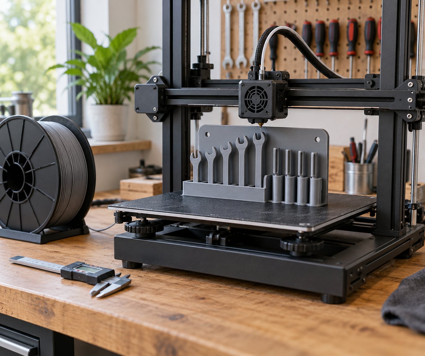
Learning how to print custom tool holders comes down to three decisions: get a model shaped around your actual tools, pick a filament that survives the load, and slice for walls rather than infill. A custom tool holder is a tray, rack or insert modeled to one specific tool or one specific drawer, so the hardware drops into a cavity cut to its outline instead of rattling around a generic bin. Most first attempts fail on fit, not on strength, which is why the measuring and clearance steps below come before the slicer.
I keep a drawer of drill bits, hex keys and calipers that are all custom printed now, and the honest truth is that the first version of almost every holder was wrong in some small way. The tool was 0.5 mm too thick for the pocket. The holder split along a layer line. Once you expect that, the whole process goes fast.
Table of Contents
- 1What You Need
- 2Step-by-Step: How to Print Custom Tool Holders
- 31. Measure the Tool and Plan the Layout
- 42. Choose a Material for the Intended Use
- 53. Model or Download the Holder
- 64. Check Fit, Orientation, and Supports
- 75. Prepare the File in Your Slicer
- 86. Print the Custom Tool Holder and Check the Fit
- 97. Tune and Print the Final Version
- 10Common Mistakes
- 11Frequently Asked Questions
- 12What material is best for heavy-duty 3D-printed tool holders?
- 13Can I make a custom tool holder if I have no CAD experience?
- 14How do I mount a 3D-printed tool holder in a workshop?
- 15What layer height and infill settings are best for tool holders?
- 16How do I clean a 3D-printed tool holder without damaging it?
- 17Conclusion
What You Need
You need four things: a 3D printer with enough build volume for the finished holder, CAD software or a model file, a slicer, and the tools you intend to store. That is the short list, but each one has a catch worth planning around.
A printer with a 200 mm or larger bed handles a drawer baseplate or a wall rack. Anything smaller and you are limited to single-tool holders and small bins. If your holder has to be printed in pieces, plan on designing the joint now rather than discovering the fit problem at hour nine.
For software, a slicer is mandatory and a free one is fine. PrusaSlicer, Cura, OrcaSlicer and Bambu Studio all handle tool holders well, and each has a solid inspection mode that shows you overhangs before you commit. CAD is optional if a community model already fits your tools, and worth learning if your tools are non-standard sizes.
A pair of digital calipers is the one measuring tool I would not skip. Guessing a socket diameter from memory is how you end up reprinting. A tape measure handles drawer dimensions, and a straightedge helps you check the finished baseplate for square corners.
On material, match the filament to the job. Lightweight bins for screwdrivers and hex keys print fine in PLA. Anything that carries a drill, a socket rail or a drawer full of steel wants PETG or nylon. If the holder lives near a soldering iron, a heater or a hot tool, pick a material with real heat headroom.
Step-by-Step: How to Print Custom Tool Holders
1. Measure the Tool and Plan the Layout
Start by recording six things for every tool: width, depth, height, handle shape, how much access you need, and which way it sits when stored. Measure the widest point, not the handle or the tip. A 13 mm chrome wrench often measures 14 mm across the ring, and that 1 mm decides whether it drops in.
Write the numbers down in a simple table before you open any software. Include the orientation each tool is likely to live in, and flag tools you grab constantly so they go in the most accessible position rather than the neatest one.
Add a fit allowance to every cavity. For a tool that should slide in and stay put, I start with 0.3 mm of clearance per side on a typical FDM printer, then adjust after the first test. For a slot a tool drops into from above, a slightly tighter figure of 0.2 mm per side works because nothing needs to pass through a side wall.
The success check here is simple: you should be able to say, without guessing, how deep the cavity is and how much clearance sits on each side.
2. Choose a Material for the Intended Use
PLA is stiff, easy to print and accurate, which makes it a good default for anything light. It softens near 50 to 60 Celsius, so keep it away from hot tools and direct sun on a bench. Under a sudden side load it can snap rather than bend, so it is a poor choice for a rail holding heavy pliers.
PETG is the workhorse for workshop holders. It is tougher than PLA, tolerates heat around 70 to 80 Celsius, and holds layer adhesion better when a cavity edge takes repeated tool contact. It strings a little more and needs a slightly higher nozzle temperature than PLA, which is the trade you accept.
ABS and ASA handle roughly 90 to 100 Celsius and resist chemicals and UV, which matters if the holder sits outdoors or near a battery charger. Both need an enclosure to control warping on anything larger than a small pocket, and ASA survives outdoor UV where ABS degrades.
TPU is the flexible option and the only one I would use for a grippy tool mat or a phone-side caddy. It resists abrasion and impact, but it is soft, it clogs in some nozzles if printed hot and fast, and it makes tight dimensional cavities less predictable. Nylon sits at the far end: very tough, very tough on the printer, and moisture-hungry, so it wants a dry box and slower speeds.
3. Model or Download the Holder
Downloading is fastest when a community model already matches your hardware. Thingiverse, Printables, MakerWorld, Cults and MyMiniFactory all host thousands of tool organizers, and checking model reviews tells you quickly whether the pockets actually hold the tools they claim to.
Designing your own takes longer but solves the problem exactly. In Fusion 360, FreeCAD or Onshape, sketch the tool outline to the dimensions you measured, offset it by your clearance figure, then use that outline as the profile for a pocket cut into a base block. That single operation gives you a cavity that follows the tool exactly.
Keep the wall thickness between the cavity and the outside of the block at 2 mm or more, and put mounting features into the model from the start: screw holes with counterbores, pegboard holes on a 25 mm grid, or a magnet pocket sized to the magnet you actually own. Fillets at the bottom of each pocket matter too, because a sharp internal corner is where a printed layer usually cracks first.
The check: export as STL, then reopen the file and use the slicer’s repair tool if it reports problems. A malformed mesh that prints at 99 percent and then tears is more common than people expect.
4. Check Fit, Orientation, and Supports
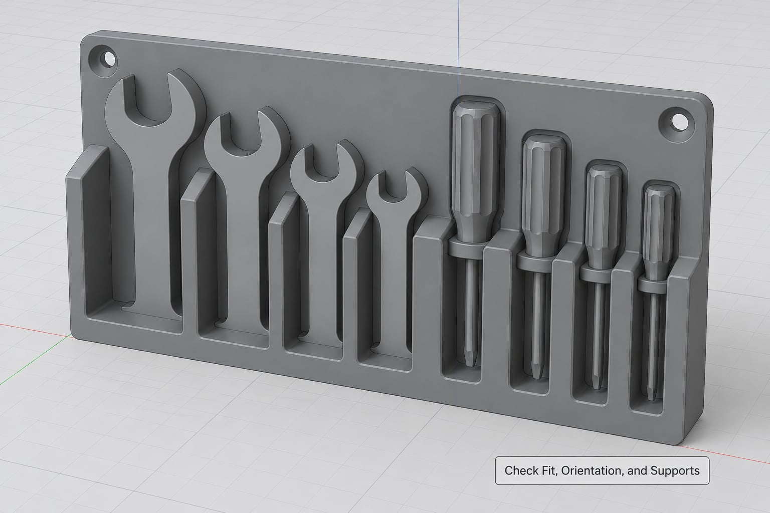
Run the inspection view in your slicer before anything else. It flags thin walls, overhangs and islands without slicing, which takes seconds instead of an hour.
Confirm your minimum clearances by re-measuring the model, not the drawing. If a pocket needs to clear a 6 mm hex key, the finished opening should measure a touch more than 6 mm after accounting for elephant-foot rounding on the first layer.
Orientation decides strength more than infill ever will. Print a rail or a wall-mounted rack standing on its mounting face so the load from each tool pushes down through the layers rather than peeling them apart sideways. Tray-style holders print best lying flat, with the tool cavities opening upward, so no support is needed inside them.
Add support only where an overhang runs past roughly 50 degrees for your filament, and never inside a tool cavity. If support has to sit where a tool slides, the tool will drag it off. Flip the part, change the orientation, or accept a slightly worse-looking overhang before you accept support in a friction zone.
5. Prepare the File in Your Slicer
Import the STL and set units to millimeters, then let the slicer detect the build plate. Most slicers fill a default plate size from the printer profile, and that default is often wrong for your machine.
Set the wall count before infill, because walls do most of the strength work. Four perimeters is a good default for a load-bearing holder. Then choose an infill pattern that resists shear: cubic, gyroid or octet behaves far better under a sideways shove than plain grid lines, which separate along their length. Twenty to thirty percent is enough once the walls are right.
For a small pocket 6 mm wide or narrower, drop the layer height to 0.12 or 0.16 mm. A 0.4 mm nozzle can technically print at 0.1 mm, but the effective resolution does not improve and print time climbs sharply, so the tradeoff rarely pays off outside a fine-detail model.
Set temperatures last. With PETG, start around 240 Celsius at the nozzle and 80 Celsius on the bed, then let the first layer tell you more than any table does. Raising bed temperature does help adhesion on large flat baseplates, and dropping a few degrees helps when corners start lifting instead.
6. Print the Custom Tool Holder and Check the Fit
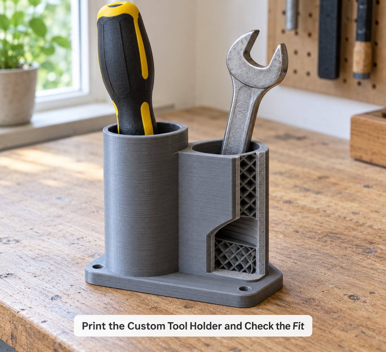
Clean the build plate before every large print. Isopropyl alcohol on a textured or coated PEI sheet removes the skin of oil that turns a good first layer into a lifted corner, and it takes ten seconds.
For a wide, flat baseplate, add a brim or a short raft. It costs a few grams of filament and it stops the outer edges from curling on a cool room. Check the first layer in the preview before committing hours, then watch the first three layers on camera if your printer has a webcam.
When the print finishes, let the plate cool fully before you pull anything off. Prying a PETG part warm will bow it, and the bow is permanent.
The test fit is the moment of truth, and do it gently. Try one tool, in one cavity, with light pressure. If it slides in but falls straight out, your clearance is too generous and you need to drop it by 0.1 mm per side. If it will not go in at all, add clearance rather than forcing it, because forcing it can split the pocket wall along the layer line and send you back for the whole print.
Look for wobble with the holder empty, before any tools go in. A holder that rocks on the bench usually means a warped baseplate, and no amount of tool load will fix that. A tilt or a cup is worth a reprint; adding weight to it is not.
7. Tune and Print the Final Version
Your test fit gives you one or two numbers to change. Tight pockets get more clearance, loose ones get less, and a holder that only wobbled gets a brim plus a slower first layer. Those are small edits in the slicer, and they are cheaper than redesigning the model.
Then handle the finish. Print walls of 4 to 5 perimeters and four or five top and bottom layers for any holder that carries real weight, since a tool hanging over a pocket edge applies load exactly where top layers matter. For a visible rack, iron the face after printing or spray-paint it, and paint the cavities in a contrasting color so a missing tool is obvious from across the bench.
Mount it properly. Screw-mounted racks need washers that spread load on the printed surface, and a pocket around a magnet needs a press fit with a light interference, not a loose drop-in. Clip or screw the holder to the bench rather than to drywall.
Print the final version in the material you chose in step two, and keep the successful slicer profile saved. The second holder for a different tool will take a fraction of the time, because all the guesswork is already done.
Common Mistakes
The tool does not fit. Almost always clearance, not geometry. Increase the cavity by 0.2 to 0.3 mm per side and reprint only that holder; most models are small enough to redo quickly. If you measured in the CAD sketch but not the finished STL, trust the STL.
The holder wobbles or rocks. Warping on a wide flat part, or a baseplate that is not sitting flat. Add a brim, raise the bed a few degrees, and check that the part is not being pulled off before it cools. Re-level the plate too.
It splits along a layer line. Weak layer adhesion under a sideways load. Raise nozzle temperature, slow the outer wall speed, and increase wall count. If the split happens at a sharp internal corner, add a fillet in the model, because that is a stress riser no slicer setting will remove.
Mounting points rip out. Too little material around a screw hole, or a magnet pocket with no lip. Add a boss around the hole, thicken the back wall, and give the magnet pocket an interference fit.
The tool is hard to remove. A pocket that is a fraction too tight, or friction in a cavity with support residue. Sand the pocket walls lightly, or add a small chamfer at the entry so the tool leads in instead of catching.
Supports land inside a cavity. The support was in the wrong place. Change the orientation first, and use support blockers or a lower threshold before accepting a support island inside a friction zone. Stringy blobs inside a pocket are usually what people actually mean when they say the holder is bad.
Visible stringing and rough cavity walls. Retraction and temperature. On PETG, try lowering nozzle temperature in small steps, enable or raise retraction distance for your extruder, and slow the outer perimeter speed. Bump ironing on the top surface only.
The drawer version comes out the wrong size. Measure the drawer at the back, not just the front lip, and add 0.5 to 1 mm total clearance for the drawer slides. Old drawers swell and warp, and the tightest point is rarely where you measured first.
Frequently Asked Questions
What material is best for heavy-duty 3D-printed tool holders?
PETG is the best all-round choice for holders carrying real tool weight. It is tougher than PLA, resists heat around 70 to 80 Celsius, and holds layer adhesion better under repeated contact. Nylon is tougher still if your printer can handle its moisture and you will use heat-set inserts. PLA suits light bins and low-heat locations only.
Can I make a custom tool holder if I have no CAD experience?
Yes. Thousands of free tool holder models sit on Printables, Thingiverse, MakerWorld, Cults and MyMiniFactory, and community models cover most standard wrench sets, hex keys and drill bits. When nothing fits your exact tools, tracing or photographing the tool and generating a cavity from that outline is easier than learning a full CAD program.
How do I mount a 3D-printed tool holder in a workshop?
Screws into studs or plywood are the most secure, and the model needs a boss around each hole so the printed surface is not crushed. Clamp-on designs that grip a bench edge avoid all wall fixing. Pegboard holes on the standard grid work with simple pins, and a magnet pocket with a tight interference fit suits steel toolboxes.
What layer height and infill settings are best for tool holders?
Start at 0.2 mm layer height with four perimeters, then drop to 0.12 or 0.16 mm for pockets narrower than about 6 mm. Infill of 20 to 30 percent in a cubic, gyroid or octet pattern handles load well once the walls are right. Walls do most of the strength work, so raise perimeters before you raise infill.
How do I clean a 3D-printed tool holder without damaging it?
Warm water with a drop of dish soap and a stiff brush handles grease and metal swarf, and a toothbrush gets into tool-shaped cavities that will not take a rag. Avoid dishwashers, solvents and acetone on printed parts, since PLA softens and PETG can craze. Let the holder dry fully before returning tools that may be damp.
Conclusion
Start with the least glamorous step: measure the tool with calipers, then model or download a cavity 0.3 mm larger on each side and print only that one pocket as a test. The fit tells you more in twenty minutes than another full holder would tell you in three hours.
From there the path is short. Pick PLA for light bins and PETG for anything carrying real tool weight, set four perimeters with modest infill, print the holder flat with supports kept out of the cavities, and test-fit one tool before committing to the final version. Save the slicer profile and the second holder takes a fraction of the time.
Updated for 2026. If a holder breaks along a layer line under load, raise the walls before you raise the infill percentage, and if it will not hold a tool, fix the clearance before you blame the material.