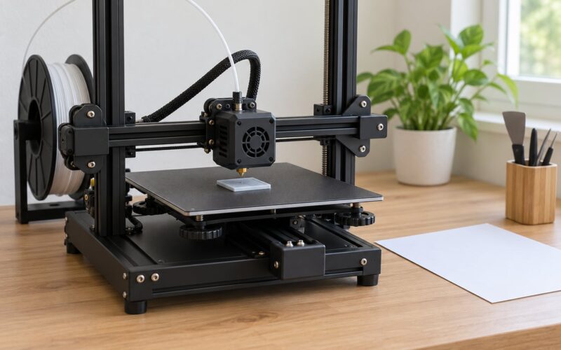
Z offset is the vertical distance between where your printer’s firmware thinks Z equals zero and where the nozzle tip actually sits over the bed. That single number decides whether your first layer squishes down and sticks, or floats in stringy little ropes. Setting it takes about fifteen minutes if your printer homes reliably, and almost every first-layer problem people blame on bad filament really comes down to this gap.
Before you touch a menu, it helps to know there are three different things people call Z offset, and only one of them is a number you type in. A slicer can apply an offset to every print. Firmware can hold one in EEPROM. On a printer with no probe, the “offset” is physical: a switch bracket you slide by hand. Get that straight first and the rest is mechanical.
Table of Contents
- 1What You Need
- 2Also worth having on hand
- 3Step-by-Step: Set Z Offset for a Reliable First Layer
- 41. Identify Where Your Printer Stores the Z Offset
- 52. Clean the Build Plate and Check the Nozzle
- 63. Level the Bed and Run a First-Layer Test
- 74. Adjust the Z Offset in Small, Controlled Increments
- 85. Save the Setting and Verify It With a Real Print
- 9Common Mistakes
- 10Quick checklist before you blame the offset
- 11Frequently Asked Questions
- 12What does Z offset mean on a 3D printer?
- 13Should I adjust Z offset before or after leveling the bed?
- 14How do I know if my Z offset is too low?
- 15Where is Z offset in Cura or PrusaSlicer?
- 16Does Z offset change for every filament or material?
- 17Why does my first layer look good at one point but bad at another?
- 18Conclusion
What You Need
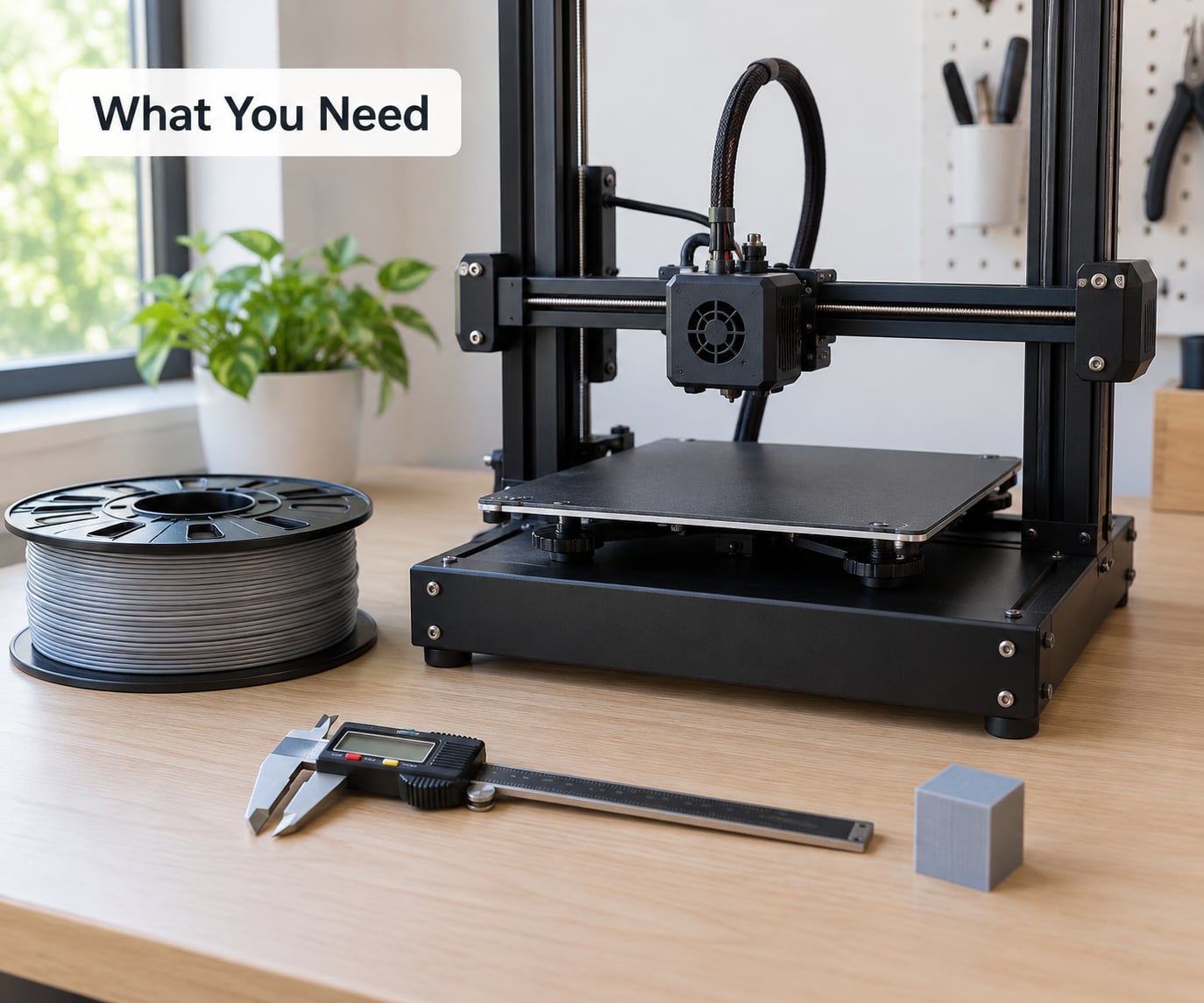
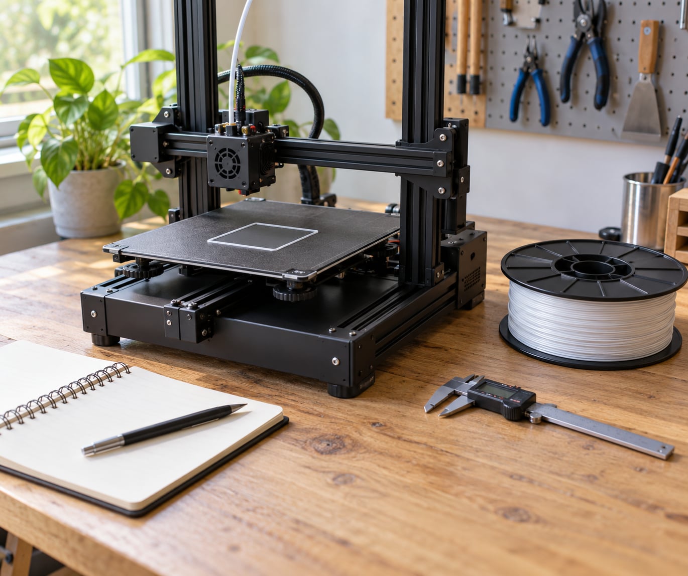
You need very little, which is why this is a good first calibration to learn. Grab a thin piece of ordinary printer paper or a set of feeler gauges, a flashlight, and your printer’s manual so you know which kind of machine you are holding.
A first-layer test model helps more than anything else. A single-layer square, roughly 60 by 60 millimetres with a brim around it, shows you the whole surface in about three minutes. If you would rather not hunt one down, slice a small cube, stop the preview at the second layer, and print only that first layer.
Have your slicer open alongside the printer screen, since you will probably move between the two. A caliper is useful later if you want to measure nozzle diameter, though you can skip it for the offset itself.
One safety note before you start: a hot bed at 60 degrees and a hotend at 200 will melt skin fast, and a too-low offset can gouge a textured PEI sheet or scratch glass. Let the printer cool before you slide paper under the nozzle, and never force anything against a hot plate.
Also worth having on hand
- Isopropyl alcohol and a lint-free cloth for a dirty plate
- A flashlight or phone torch to read the line by side light
- A soft brass or silicone nozzle brush for a clogged tip
- A notebook or note on your phone to record the final value
Step-by-Step: Set Z Offset for a Reliable First Layer
1. Identify Where Your Printer Stores the Z Offset
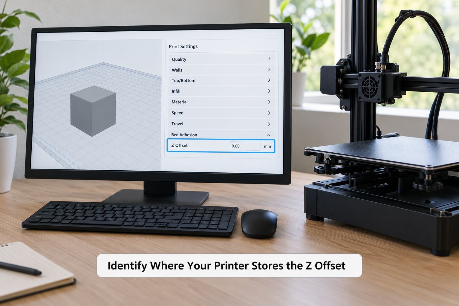
A Z offset can live in three different places, and each one behaves differently. A slicer offset shifts the model in software every time you slice. A firmware offset sits in the printer’s EEPROM and applies to every print from every slicer. A physical offset is the gap built into the machine by the Z endstop switch position, and it only exists on printers with no probe.
Start by finding out which one you have. If your printer has a BLTouch, CR Touch, inductive probe or any sensor that measures the bed, the offset is a firmware number. If it homes onto a switch, there is no offset value anywhere, and the switch position is your calibration.
| Printer or firmware | Where the offset lives | How to save it |
|---|---|---|
| Marlin with a BLTouch or CR Touch (common on Ender 3 and Ender 5 builds) | LCD menu, Control then Bed Leveling then Probe Z Offset | Store Settings, then confirm |
| Marlin using the probe as a Z endstop (M851 path) | G-code M851 sets the probe offset | M500 stores it to EEPROM |
| Klipper | z_offset under the probe section in printer.cfg | Restart Klipper, or SAVE_CONFIG after editing |
| Prusa firmware | Calibration menu, Z offset wizard or Manual Z calibration | Wizard saves to EEPROM itself |
| Bambu Lab stock firmware | Bed mesh first layer inspection, or the calibration menu | Saved automatically |
| Printer with a Z endstop switch only | No stored value, the switch bracket position is the setting | Move the bracket, retighten, power cycle |
| Cura or PrusaSlicer | Profile or machine settings, not in the printer | Saves with the profile |
Exact menu names moved around between firmware versions, and the current builds most people flash in 2026 reorganised several of these screens. If your menu does not match what you see above, search the manual for your firmware version rather than guessing.
Slicer-only offsets are worth understanding because they are temporary and easy to over-trust. Cura needs a plugin for a global offset, and PrusaSlicer has an initial Z offset field under machine settings. Either works for a test, but if your real firmware gap is wrong, the slicer is quietly hiding a mechanical fault. Set it in the printer if your printer has a probe.
2. Clean the Build Plate and Check the Nozzle
Wipe the plate with isopropyl alcohol and let it dry fully. Dust, fingerprints and a thin film of grease are the most common reason a first layer will not hold, and no amount of offset tuning fixes them. If you have textured PEI, a quick scrub with a dish sponge while the plate is warm works well; on smooth PEI, alcohol alone is enough.
Check the sheet itself. A textured plate that has been scraped down to shiny plastic, or a glass bed with a permanent smear or a chipped edge, will not behave like the plate the offset was tuned for. That is a replacement job, not a calibration job.
Now look at the nozzle tip. A partial clog makes a blobby, uneven line that looks suspiciously like a bad offset, and it can also cause the classic first-layer failures. Heat the hotend, push filament through, and wipe the tip with a brass brush. Hold a flashlight up to it and look for a clean, even cone. If the tip is visibly damaged, replace the nozzle before you calibrate, because a chewed or partially blocked nozzle changes flow and will drag your first layer around.
Wait for the bed and hotend to cool to a comfortable handling temperature before the next step.
3. Level the Bed and Run a First-Layer Test
Level the bed first, every time. It feels backwards to some people, because bed leveling is about flatness and Z offset is about height, but they are different corrections for different problems. A perfectly set Z offset on a tilted bed still gives you a gappy corner, and that is exactly how people end up chasing an offset that was never wrong.
Use your printer’s own procedure. Manual printers usually mean four corner adjusters and a piece of paper, or a glass bed you set in one corner while testing all around it. Probe printers usually mean running mesh bed leveling so the firmware has a plane to work from. Either way, do it before you change any number.
Slice your test model at a first-layer height of 0.20 millimetres with a 0.4 millimetre nozzle, add a brim, and print it. Watch the first line if you can. Then take the plate off and hold it up to a light, or lay it on a flat surface and run a fingernail across it.
Here is what you are looking for. A correct line is flat and slightly shiny, with the edges of adjacent lines merged and no ridges you can catch a fingernail on. Too high and the lines are round, separate, and you can see daylight between them. Too low and the surface has visible ridges, the plastic is nearly translucent, and the lines have been smeared into the plate.
4. Adjust the Z Offset in Small, Controlled Increments
Change one thing at a time, in small steps. Most firmware menus move by 0.02 millimetres per press, and Klipper lets you fine-tune with Live-Z at 0.005 millimetres. Those are sensible increments, because the difference between a good first layer and a ridged one can be well under a tenth of a millimetre.
The sign convention trips up almost everyone. A more negative Z-offset moves the nozzle closer to the bed. A more positive value moves it further away. Read that twice, because the words “lower the nozzle” and “make the number smaller” mean the same thing, and confusing them is the single most common thread on calibration forums.
| What the first layer looks like | What it means | Which way to move it |
|---|---|---|
| Round, stringy lines with visible gaps | Nozzle too high, nothing is touching the plate | More negative, towards the nozzle |
| Lines stick but peel away in curves | Slightly too high, weak contact | Slightly more negative, about 0.02 mm |
| Ridged lines, rough surface, nearly translucent | Nozzle too low, the nozzle is dragging plastic | Less negative, away from the nozzle |
| Flat line with no ridges, but the corner lifts | Offset is fine, this is a leveling or mesh problem | Leave it alone |
| First four layers fine, then it lifts mid-print | Usually bed temperature, not offset | Leave it alone, heat the bed properly |
| Only one corner or one edge sticks | Bed is not level at that spot | Level the bed, then re-test |
Work from a cold or cool plate for your first pass, since a hot plate moves. Print the test square again after each change and look. When the line looks flat and merged but still catches a fingernail very slightly, go one step further in the direction that reduces the catch.
Fine-tuning during the print itself is faster than restarting. Marlin builds have a Tune menu with baby stepping for Z, reachable from the printer screen during a print, and Klipper exposes Live-Z through Fluidd or Mainsail. Nudge the value, watch the line change under the nozzle, and keep the change if it helps. Most experienced users agree that the paper test gets you close and a live adjustment is what confirms it.
5. Save the Setting and Verify It With a Real Print
Nothing annoys me more than an offset that works twice and then vanishes. That is almost always a value you adjusted but never stored. On Marlin LCD builds, leaving the Probe Z Offset screen is not enough; you have to find Store Settings and confirm it, which writes the value to EEPROM. Marlin users who set an offset with M851 must send M500 for the same reason.
Klipper stores the value differently. You edit z_offset in printer.cfg, and if you change it in the console instead, you need SAVE_CONFIG so it survives a restart. This is the second most common cause of a Z-offset that resets after every power cycle, right behind never pressing the save button at all.
Verify with something you actually want to print, not just the test square. Small footprints and thin first-layer features are where a marginal offset shows up fastest, so a simple functional part is a better test than a large flat base.
Finally, write down the value next to the material and plate combination. PLA on smooth PEI will want one number, PETG another, and ABS on textured plate a third, because harder materials and textured surfaces behave differently as they cool. Keeping a note per setup means you are starting from a known value instead of redoing the whole process every time you swap spools.
Common Mistakes
The biggest mistake is adjusting in the wrong direction. If your lines are gappy, you need the nozzle closer to the bed, which is a more negative value, not a less negative one. Several people in printer forums described setting the offset the wrong way, making the gap worse, and concluding that Z-offset adjustments do not work.
Changing everything at once is the second one. If you move the offset, swap the plate and drop the first-layer speed in the same five minutes, you cannot tell which one helped. Change the offset, print the test, judge the test, and only then move to the next variable.
Calibrating cold is subtler and shows up later. A probe’s trigger point drifts as the hotend heats up, and the bed itself expands. Prusa and general FDM forum threads both point at homing-while-heating as a reason offsets that looked perfect at room temperature behave differently mid-print. Set your offset with the hotend and bed at your normal print temperatures, and let the machine sit for a few minutes first.
Confusing Z offset with bed leveling is the most expensive misunderstanding. Leveling corrects tilt. Offset corrects a single height. A mesh correction handles a surface that curves slightly. If you turn a perfectly good offset into a bad one chasing a tilted corner, you will have to level the bed and start over.
Confusing it with Z-hop is harmless but irritating. Z-hop lifts the nozzle on travel moves so it does not drag across finished prints. It has nothing to do with where your first layer sits, and changing it will not fix a first layer.
Finally, do not use a slicer setting to cover up a mechanical problem. A Cura offset plugin or a higher initial layer height in PrusaSlicer will make some prints look better, and it hides the fact that the printer itself is off. It also disappears the moment someone else slices the model, which is a bad surprise in a shared lab or makerspace.
Quick checklist before you blame the offset
- Is the bed clean and free of grease?
- Is the bed level, corner to corner, after a fresh leveling pass?
- Is the nozzle clear and undamaged?
- Was the machine at print temperature when you homed?
- Do good lines appear on one edge and bad lines on the opposite edge? That is tilt, not height.
Frequently Asked Questions
What does Z offset mean on a 3D printer?
Z offset is the vertical distance between where your printer believes Z equals zero, set by the Z endstop or a bed probe, and where the nozzle tip actually sits. The firmware applies that number before printing the first layer so the plastic is slightly compressed against the build plate. Set it correctly and the first layer grips; set it too high and you get stringy lines and gaps.
Should I adjust Z offset before or after leveling the bed?
After. Bed leveling fixes tilt and flatness, while Z offset fixes a single height reference. If you set the offset first, a tilted bed will still produce a gappy corner and you will wrongly assume the offset is wrong. On probe printers, run mesh bed leveling first, then set the offset, then run your test print.
How do I know if my Z offset is too low?
A too-low offset leaves ridges you can catch a fingernail on, makes the plastic look rough or nearly translucent, and often produces a slightly wider base known as an elephant’s foot. If the plate is scored or the plastic has been smeared into it, the nozzle was dragging. Move the value less negative, about 0.02 millimetres at a time, and print the test square again.
Where is Z offset in Cura or PrusaSlicer?
In Cura you generally need a third-party offset plugin, because the settings are tied to a printer profile and one number covers every print. PrusaSlicer exposes an initial Z offset field under Machine settings that is applied during slicing. Both are slicer-level values, so they mask rather than fix a firmware or mechanical gap. Exact field names vary by slicer version, so check your own version’s documentation.
Does Z offset change for every filament or material?
Not exactly, but close enough to matter. PLA is the most forgiving. PETG and ABS tend to need slightly different settings, harder materials shrink more as they cool, and flexible filaments can string and smear if the nozzle is too close. Swapping a smooth PEI sheet for a textured one also changes what a good gap looks like. Record a separate value for each material and plate combination you use.
Why does my first layer look good at one point but bad at another?
That is a leveling or mesh problem rather than a Z offset problem, because a Z offset is one height applied across the whole bed. A good centre with bad corners usually means the bed is tilted or the mesh is stale. Re-run bed leveling, make sure the plate is seated flat and clean, and print the test square again before touching the offset value.
Conclusion
Start here: clean the plate with alcohol, run a full bed leveling pass, then print a small single-layer square with a brim and look at the line under a light. Gaps and round stringy lines mean the nozzle is too high, so make the value more negative in steps of about 0.02 millimetres. Ridges and smeared plastic mean it is too low, so move the other way.
When the line looks flat and merged, save the value properly with Store Settings, M500 or SAVE_CONFIG, then confirm it with a real print. Write the number down for each filament and plate combination, and your first layer problems will mostly disappear.