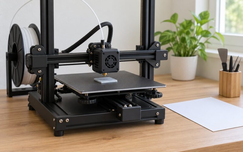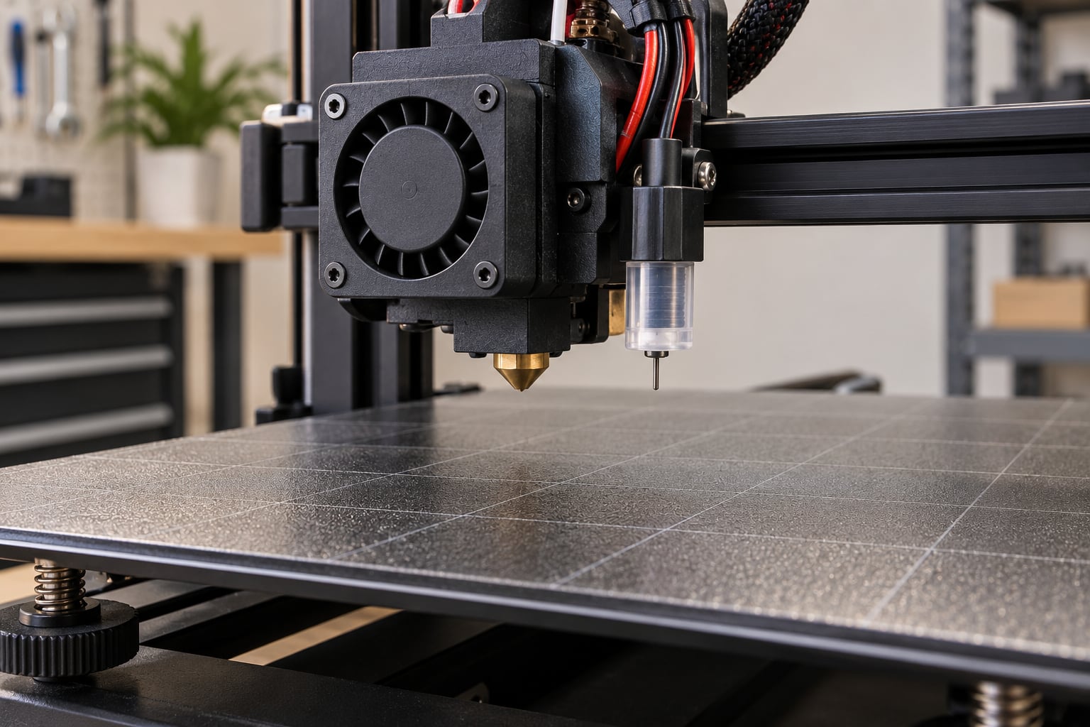
An auto bed leveling probe is a small sensor mounted on the print head that measures the build plate at several points and builds a height map the firmware uses to hold the nozzle a fixed distance from the bed. Using one correctly means more than switching it on: the probe offset, the Z-offset, the mesh, and the start G-code all have to agree.
This guide covers how to use auto bed leveling probes correctly on any FDM machine, whether you run stock Marlin or converted to Klipper. Budget about 30 minutes for a full setup and five minutes for routine re-checks before a print.
Two numbers cause most of the confusion. The probe offset is the gap between your nozzle tip and the sensor’s trigger point when the pin is deployed. The Z-offset is the final nozzle-to-bed distance the machine holds during the first layers. Set the first one roughly right and the machine will let you fine-tune the second one safely.
Table of Contents
- 1What You Need
- 2Step-by-Step: How to Use Auto Bed Leveling Probes Correctly
- 31. Confirm What Your Probe Measures
- 42. Prepare the Printer Safely
- 53. Set a Reasonable Trigger Height
- 64. Run the First Mesh or Grid Check
- 75. Check the Nozzle-to-Bed Clearance
- 86. Update Slicer Settings
- 97. Test and Recalibrate When Conditions Change
- 10How to Confirm Auto Bed Leveling Is Actually Running
- 11Common Mistakes
- 12Fix an Unreliable or Failing Probe
- 13Fix a Poor First Layer
- 14Final Calibration Tips
- 15Frequently Asked Questions
- 16What is the difference between a BLTouch probe and an inductive bed probe?
- 17Should I use paper to set the Z-offset after automatic bed leveling?
- 18Why does my printer keep probing the same spot or fail mesh leveling?
- 19Does auto bed leveling replace leveling by hand?
- 20How often should I rerun bed leveling on an FDM printer?
- 21Conclusion
What You Need
Before touching a calibration menu, know four things about your setup.
- Your probe type. A deployable mechanical pin (BLTouch, CR Touch and similar), a fixed inductive or optical sensor, or a strain gauge that measures the nozzle itself.
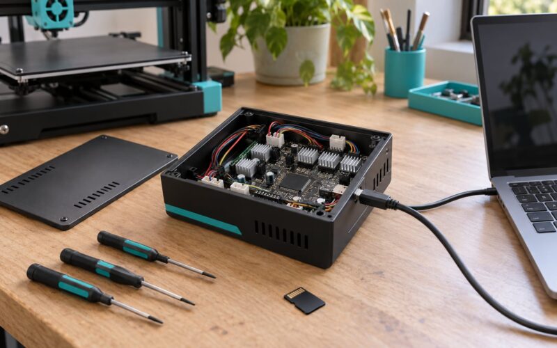
- Your control board and firmware. Marlin with a Creality or SKR Mini E3 board, Klipper on a Raspberry Pi, or a printer vendor’s own interface. Menu names differ enough that guessing wastes a lot of time.
- Your slicer and version. PrusaSlicer, Cura, OrcaSlicer and others expose bed probing differently.
- A feeler gauge or thin shim stock, plus a way to send G-code by hand, such as a printer console in Pronterface, OctoPrint, or the machine’s own serial terminal.
Your printer’s manual is part of the toolset. Probe wiring is polarity-sensitive on every 3-and-2 pin arrangement, and reversing 5V and ground destroys the sensor. Follow the board’s silkscreen and the manual rather than a generic wiring diagram.
Two optional tools earn their keep: an infrared thermometer for checking bed temperature before probing hot, and a machinist’s straight edge for spotting a bent gantry or a warped plate that no mesh will fix.
Step-by-Step: How to Use Auto Bed Leveling Probes Correctly
Work through these in order. Each step assumes the previous one is right, and each gives you a way to confirm it worked rather than asking you to trust the screen.
1. Confirm What Your Probe Measures
A deployable pin probe lowers a spring-loaded pin until it touches the bed, then reports the trigger height to the firmware. The pin physically pushes back into the probe body, so what triggers is the pin tip, not the nozzle.
An inductive probe senses a metal target through the gap, usually a small copper or steel patch on the bed surface. It never touches anything and never moves. It cannot probe glass, PEI or a textured powder-coated sheet unless the surface is electrically conductive and the sensor is matched to it.
A strain gauge probe measures the deflection of the hotend itself when the nozzle touches down. Because the nozzle is the measuring element, there is no nozzle-to-probe offset to lose. On dual-Z printers with two independent Z drivers, a plain strain gauge probe on one side will read the bed as sloped unless the machine also has an auto-align routine such as Marlin’s G34.
Optical and other fixed sensors behave like inductive probes: no contact, and the trigger point is a fixed distance from the nozzle tip. Confirm which kind you have by checking what physically moves when you run a deploy or stow command.
2. Prepare the Printer Safely
Home the axes first with G28. If your firmware supports it, use safe Z homing so the nozzle probes before the Z axis takes its position. Never calibrate from a cold, unhomed machine; the numbers you read will be meaningless.
Then confirm three things in firmware. The probe type must be declared correctly, or the firmware will look for the wrong signal. The deploy and stow commands must be assigned to a real servo or control pin. And homing must be set to use the probe rather than a Z limit switch if your machine has a probe-controlled Z endstop.
Clear the bed. A single blob of filament, a scrap of tape, or a brushed-off bit of string will produce a probe point that is a fraction of a millimetre high and drag the nozzle into the plate on the next pass.
Finally, watch one full deploy and probe cycle and make sure the nozzle can physically reach every calibration point. On a large bed, probe points near the front and rear edges need enough room below the gantry to descend without hitting the frame.
3. Set a Reasonable Trigger Height
The trigger height, called the probe offset or Z-offset depending on firmware, tells the machine how far below the nozzle the sensor fires. A useful starting point for a deployable pin probe is about 2 mm to 3 mm. Inductive and optical probes usually sit much closer, often under 1 mm.
These are starting points, not answers. A probe mounted higher on the carriage needs a larger value; one mounted closer needs a smaller one. Set the nearest value, then let the machine’s own procedure find the rest.
In Marlin the value is NOZZLE_TO_PROBE_OFFSET, often called the Z probe offset in the LCD menu, and it is stored in EEPROM. In Klipper it is set with SET_PROBE_OFFSET, and Klipper will compute the number for you during PROBE_CALIBRATE. Some stock Creality boards expose a Blade-style probe distance screen instead. The path in your firmware docs is the one to trust.
Whichever you use, finish by saving. In Marlin, M500 writes the value and M501 reads it back. Saving without reloading is a very common reason a setting appears to revert on the next power cycle.
4. Run the First Mesh or Grid Check
Run the firmware leveling routine: G29 on Marlin, or BED_MESH_CALIBRATE in Klipper. Watch the first two or three points before walking away.
A healthy run reports a position for each point, a final mean, and a mesh that gets saved. In Marlin, G29 L0 prints the live tilt so you can see how far off level you are. A failed point says the probe did not trigger, and the machine will usually retry a couple of times and then abort.
If a point fails, stop and fix that before rerunning. Check the surface under that point for debris, then check the probe pin retracts fully. On a pin probe, a blob of filament stuck around the pin is the usual culprit. Do not keep rerunning G29 over a point that keeps failing; the mesh that gets built from bad data is worse than no mesh.
Grid density is a trade-off. A 5 by 5 grid is fast and fine for a well-conditioned bed. A 7 by 7 or 9 by 9 grid catches more variation at the cost of a longer routine. Keep a probing margin of about 20 mm so the edge points stay off the plate’s frame.
5. Check the Nozzle-to-Bed Clearance
After the mesh exists, verify the actual gap with a feeler gauge. Heat the bed and nozzle to printing temperature, run G28, zero the Z position, then slide the gauge under the nozzle at the centre and at each corner.
Standard 0.04 mm paper is roughly 0.1 mm thick, so leveling until paper barely moves leaves a real gap wider than most first layers want. That is why the paper method and probe leveling disagree: the paper method has a built-in offset. Use a proper feeler gauge and target the first layer height you actually slice, typically 0.2 mm for a 0.4 mm nozzle.
Paper and feeler gauges also disagree on warped and textured surfaces. On a warped plate the gap changes across the bed in a way no single measurement captures. On a powder-coated or textured sheet, the ridges you feel are taller than the nominal surface and the gauge reads high, so the nozzle ends up too far away.
On a strain gauge probe, the nozzle contact test is the built-in calibration and no separate gauge is needed.
6. Update Slicer Settings
The firmware result only helps if the slicer asks for it. In PrusaSlicer, enable bed probing in the printer settings so the printer profile uses the probe; in Cura, the equivalent setting lives under Printer, then Probe Settings. Both need the probe type declared in the printer profile rather than only in the firmware, and both need the correct nozzle-to-probe offset if you are overriding it in software.
Z-hop matters when the nozzle must lift to clear the probe pin or a blob on the plate. Keep the hop height at or below the first layer height so the nozzle does not travel further than the layer it is laying down. Probing temperature is another free parameter: probing at bed temperature produces a mesh that matches a warm plate, and most people do better probing hot rather than cold, because it captures the thermal state the print will actually run in.
Slow the first layer slightly. Running it at the normal speed squeezes the bead and hides small errors; a slower first layer shows the problem.
Now the step most guides bury. Your start G-code must load the mesh. On Marlin that means:
G28
G29 L0
M420 S1
M420 S1 tells the firmware to enable the stored mesh and the leveling correction. Without that line the machine homes, ignores the mesh it just built, and prints with a raw Z that was never calibrated. This single missing command is the most common reason people say their mesh works but their first layer does not.
On Klipper, the equivalent is to call the mesh from your START_PRINT macro, and Klipper saves the mesh automatically rather than through an EEPROM toggle.
7. Test and Recalibrate When Conditions Change
Print a small first-layer test model rather than starting the real job. Look at the bottom surface: lines merged into a flat sheet with no ridges means the gap is right, lines you can pick apart with a fingernail means too high, and lines squashed flat or cut into the sheet means too low.
High corners with a low centre point to bed warp or a loose frame. Low corners point to a warped plate or a probe mount that moved. A consistent offset in one direction across the whole plate means the Z-offset, not the mesh, is off.
Rerun leveling when conditions change, not on a schedule. You need it again after moving the printer, swapping or tightening the nozzle, removing the build plate, changing the plate material, a firmware update, or any crash where the head took a load.
How to Confirm Auto Bed Leveling Is Actually Running
If you want proof rather than assumption, M48 on Marlin runs a probe accuracy test. It drops the probe at one spot about 100 times, prints the mean, the spread and the standard deviation. A standard deviation under roughly 0.003 mm means the sensor and its mount are mechanically sound. Above 0.01 mm points at a mechanical fault: a loose probe mount, a bent pin carrier, or a gantry that moves under load. Klipper has the same idea through the probe repeatability report.
To confirm the mesh is loaded at print time, watch the printer during the first layer. A probing routine that runs visibly, followed by a saved-mesh message or an LED status change, means the mesh is active. In Klipper you can also query the saved mesh state from the console at any time.
Common Mistakes
Nearly every auto bed leveling problem shows up as a bad first layer or as probing that will not complete. Work the symptom, not the guess.
| Symptom | Likely cause | Fix |
|---|---|---|
| Mesh probes fine but the first layer is bad | Start G-code never loads the saved mesh | Add M420 S1 after G29 L0, or load the mesh macro in Klipper |
| Setting reverts after a power cycle | Value written but not reloaded, or never stored | Run M500 to save and M501 to reload |
| Nozzle scrapes the bed right after homing | Probe offset too small, so the probe never triggers before contact | Increase the probe offset in small steps and re-home |
| Nozzle drifts off the edge of lines across the plate | X and Y probe offsets measured in the wrong direction | Re-measure with the probe deployed and correct the signs |
| Probing aborts at the same point | Debris on the plate or a pin that will not retract | Clean the spot and the pin, then rerun |
| Good first layer at the start, ridges by layer 5 | Probe temperature drift, common on inductive sensors | Probe hot, and reduce the mesh fade height so correction ends sooner |
| One corner consistently reads high | Dual-Z gantry not square, with no auto-align enabled | Square the gantry manually or enable G34 auto-align |
| Fine for a short print, wrong after 20 minutes | Bed warmed after the mesh was built | Preheat the bed fully before probing |
Fix an Unreliable or Failing Probe
A pin probe that will not deploy usually has a mechanical cause: a servo that is not receiving the signal, a mount that shifted, or a control pin assigned to the wrong output in firmware. Check the physical pin angle first. A correctly set probe sits just below the nozzle tip, roughly 8 mm to 10 mm, and stays there.
Repeated probing at one spot usually means the firmware hit its retry limit there. Debris on the plate, a warped spot, or a pin that is not extending far enough to reach all of them will do it.
False triggers on a deployable probe are almost always electrical: a loose or reversed connector, a missing pull-up on the sensor pin, or a probe routed too close to the stepper wiring. On an inductive probe, temperature is the other common cause, since many of them drift as the hotend warms.
Do not open a probe to chase a wiring fault unless the manufacturer procedure says to. The pin assembly is easy to damage and hard to realign. Check connectors and firmware assignments first.
Fix a Poor First Layer
Start by deciding whether the mesh or the offset is wrong, because the fixes differ. A mesh problem shows up as variation across the plate: one corner ridged, another corner gapped. An offset problem shows up as a uniform error in the same direction everywhere.
If the mesh is right and the offset is off, return to the feeler gauge and re-check the gap at the centre. If the mesh itself looks wrong, run a quick tilt check with G29 L0 on Marlin and correct the two knobs it reports before regenerating.
Rule out everything else too: a nozzle that has been run down or a hotend that has dropped, a build plate that needs cleaning because a previous print left film behind, bed temperature that is off target, and first-layer speed set high. Auto bed leveling fixes geometry, and it has no opinion about any of those.
Final Calibration Tips
- Run the repeatability test once after installing a probe. It separates a sensor fault from a mechanical fault in a few minutes.
- Clean the build plate and the probe pin before every calibration session, not just when something goes wrong.
- Probe with the bed and nozzle at print temperature so the mesh matches the thermal state of the job.
- Keep the mesh fade height low. Corrections that fade out early are the ones that survive a moving bed surface.
- Save a known-good state once you get a first layer you like, and write down the probe offset, Z-offset and mesh statistics next to the printer.
- Re-level after a firmware update. Firmware changes can reset stored offsets silently.
- Keep a straight edge nearby. If the frame or gantry is out of square, no amount of probing will fix it.
Frequently Asked Questions
What is the difference between a BLTouch probe and an inductive bed probe?
A BLTouch uses a spring-loaded pin that physically touches the bed and reports the trigger height, so it works on glass, PEI and textured plates alike. An inductive sensor never touches anything and senses a metal target through a gap, which means no pin to wear and no probing drag, but it only works on a conductive surface and can drift as it heats up. A BLTouch typically triggers around 2 mm below the nozzle, an inductive probe much closer.
Should I use paper to set the Z-offset after automatic bed leveling?
Only as a rough check. Standard paper is about 0.1 mm thick, so a paper test leaves a gap wider than a typical 0.2 mm first layer wants. Use a 0.04 mm feeler gauge instead and target the first layer height you actually slice. Paper is also unreliable on textured and powder-coated plates, where the surface ridges read taller than the nominal sheet.
Why does my printer keep probing the same spot or fail mesh leveling?
The probe failed to trigger at that point and the firmware exhausted its retries. Usual causes are debris or a blob of filament on the plate, a warped area, or a deployable pin that is not extending far enough to reach. Clean the spot, check the pin retracts fully, and confirm the probe offset gives enough travel. Rerunning without fixing the cause just rebuilds the same bad mesh.
Does auto bed leveling replace leveling by hand?
It replaces most of the routine, not the mechanical setup. A probe compensates for small surface variations, so the frame, gantry and belt tension still need to be square and rigid, and a badly warped plate will still print badly. A one-off manual level with a feeler gauge before you start is worth ten minutes, because it gives the mesh a sane starting point.
How often should I rerun bed leveling on an FDM printer?
Run it before a print when conditions changed, not on a fixed schedule: after moving the printer, changing the nozzle or hotend, swapping the build plate, changing plate material, updating firmware, or after a crash that loaded the head. With a stable machine and a stable plate, a mesh saved once keeps working. Many people also re-probe after a long idle period, since the bed cools and expands between sessions.
Conclusion
Using an auto bed leveling probe correctly comes down to four things in order: identify what the sensor measures, set a probe offset that lets it trigger before the nozzle touches down, build the mesh at printing temperature, and load that mesh in your start G-code with M420 S1 or the Klipper equivalent. Miss that last step and everything before it is wasted.
Start by confirming your probe type and watching one full deploy cycle, then run a quick mesh and check the nozzle-to-bed gap with a 0.04 mm feeler gauge. Print a small test model before committing to a long job, and rerun the mesh any time the machine or the plate changes.