You can speed up 3D printing without losing quality by cutting wasted motion first, then raising the speed limits that your machine can actually hold. Start with layer height and infill, tune acceleration, and enable Input Shaper if your firmware supports it. Change one setting at a time and keep every change reversible.
Most of the gain comes from work you were never going to see. Infill density, travel moves and a badly oriented model add minutes without adding quality. The harder part is knowing which speeds to leave alone, because the first layer, the outer wall and small details are where speed pushes show up as defects.
Nothing here needs new hardware to begin with. If you own an Ender 3, a Prusa MK4, a Bambu Lab or an Anycubic, the same sequence works — the exact menu names and the ceiling for each setting differ by printer, firmware and slicer version, so treat the numbers below as starting points rather than limits.
Table of Contents
- 1What You Need
- 2Step-by-Step: How to Speed Up 3D Printing Without Losing Quality
- 3Establish a Quality Baseline
- 4Use the Printer’s Reliable Speed Range
- 5Increase Acceleration and Jerk Carefully
- 6Optimize Walls, Top and Bottom Layers, and Infill
- 7Reduce Travel, Retractions, and Wipe Moves
- 8Use Temperature and Flow Tuning Selectively
- 9How to Speed Up 3D Printing Without Losing Quality in the Slicer
- 10Improve the Model, Orientation, and Workflow
- 11Run a Small Test Before the Final Print
- 12Common Mistakes
- 13Frequently Asked Questions
- 14Can I use a fast print profile without losing quality?
- 15Should I increase layer height to make 3D printing faster?
- 16Does a higher nozzle temperature allow faster 3D printing?
- 17How much should I increase acceleration and jerk?
- 18Does low infill speed make a 3D print faster?
- 19How can I tell if a faster print still has acceptable quality?
- 20Conclusion
What You Need
Before touching a single setting, you need three things: a baseline record, a test model you already know prints well, and a way to judge the result. Without the first one, you cannot tell an improvement from a change that only felt faster.
- Your printer’s real limits. Maximum print speed, travel speed and acceleration for your firmware, plus the maximum volumetric flow of your hotend. A stock single-screw 0.4 mm hotend usually tops out around 8-11 mm³/s of melt; a high-flow hotend moves far more.
- A baseline print record. Layer height, print time, nozzle and bed temperatures, speeds, acceleration, infill settings, and a note of every visible defect.
- A repeatable test model. Something with an exposed corner, a thin wall, a bridge, a hole you measure, and a flat top surface. A calibration cube or a benchy-style test body covers all of it.
- Measurement, ideally. Digital calipers for wall thickness and hole diameter. A dial indicator and a granite plate are nice extras, not requirements.
- Optional. A phone camera on a fixed stand to compare surface texture against the baseline, and a filament weight scale to confirm infill changes did what you expected.
One honest warning before you start: the fastest possible print is rarely the fastest useful print. A print that fails at hour six is slower than one that finishes badly at hour five.
Step-by-Step: How to Speed Up 3D Printing Without Losing Quality
Here is the short version, in the order I would work through it. Most people get a large chunk of the win from the first four and never need the rest.
- Raise layer height to the tallest your nozzle can lay down cleanly — usually 75% of nozzle diameter.
- Drop infill density where strength allows, and use variable infill to put material only where load actually goes.
- Raise acceleration and jerk in small steps so the machine spends less time slowing and restarting.
- Enable Input Shaper and tune pressure advance if your firmware offers them; this is the biggest free gain on most printers.
- Speed up the features nobody sees — infill, inner perimeters, bridges — and leave the outer wall where it is.
- Cut travel moves with combing, better seam placement and smarter move ordering.
- Reorient the model so supports and hidden material disappear, and walls land on the build plate.
- Test small, then commit. Keep only the changes that pass a dimensional check and a visual check.
Establish a Quality Baseline
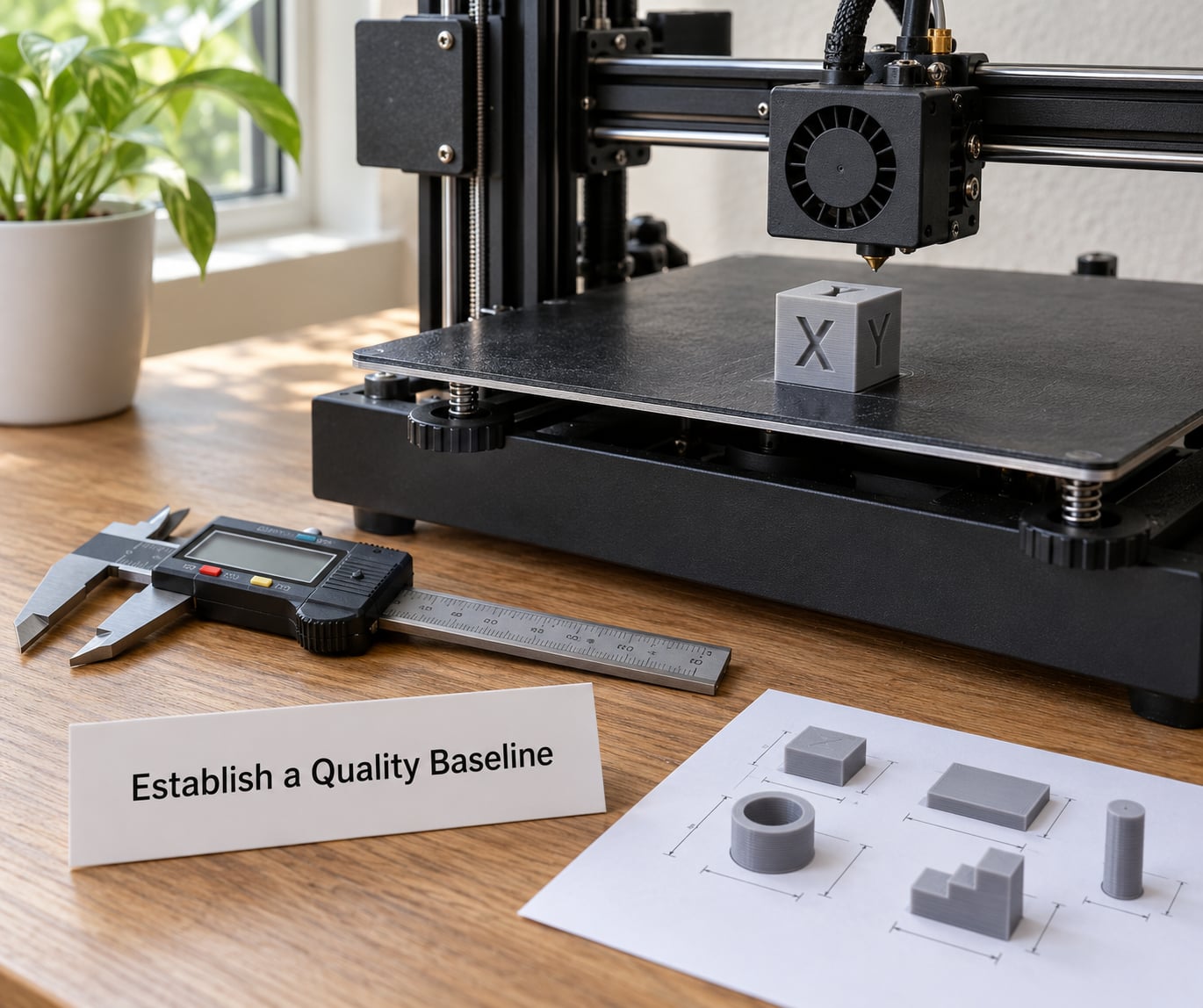
Print your test model once at the settings you use today and write down everything: layer height, print time, nozzle temperature, print speed, travel speed, acceleration, jerk or junction deviation, infill density and pattern, wall count and line width. Photograph the corners and note the measurements you care about — outer diameter, hole fit, wall thickness, flatness across the top.
This baseline is what you compare against. Speed up a setting, reprint the same model with the same filament, and put the two side by side under the same light. Without that record, the natural human bias kicks in and the faster print looks better than it is.
Use the Printer’s Reliable Speed Range
Your printer’s stated maximum speed is a firmware ceiling, not a quality recommendation. The usable number sits well below it, and where it sits depends on how well the machine is balanced, how rigid the frame is, and how good your acceleration and jerk settings are.
Raise print speed in increments of roughly 20-30% rather than jumping to a target. Watch for four specific symptoms: extrusion underextrusion where the nozzle cannot keep up, ringing or ghosting after corners, skipped or shifting layers on direction changes, and loss of fine detail on vertical features. Any one of those means you went past the reliable range.
Volumetric flow is the limit people miss. A 0.4 mm nozzle at 0.2 mm layer height and 0.45 mm line width moves about 0.036 mm² of cross-section, so 150 mm/s needs roughly 5.4 mm³/s of melt. Push to 250 mm/s on the same geometry and you need 9 mm³/s — which a standard hotend may barely deliver.
Increase Acceleration and Jerk Carefully
Print speed tells you how fast the machine moves at full tilt. Acceleration tells it how fast it can get there and how sharply it can stop and reverse. Raising acceleration removes the slow-down-and-restart penalty at every corner and direction change, which on a typical part is a large share of total time.
Jerk, called junction deviation in Klipper-based firmware, controls how sharply the machine can change direction at a corner. Too low and you get rounded corners and constant hesitation. Too high and the frame rings, which shows up as a visible ripple on vertical surfaces right after corners.
Work in small steps. Klipper community calibration typically lands somewhere between 2000 and 3000 mm/s² as a working baseline, and 5000-7000 mm/s² on a well-tuned machine with input shaping active. A community-shared settings change that users actually apply moves bridges from 80 to 120 mm/s and the first layer from 40 to 50 mm/s, which is the right shape of change: specific, modest, reversible.
Optimize Walls, Top and Bottom Layers, and Infill
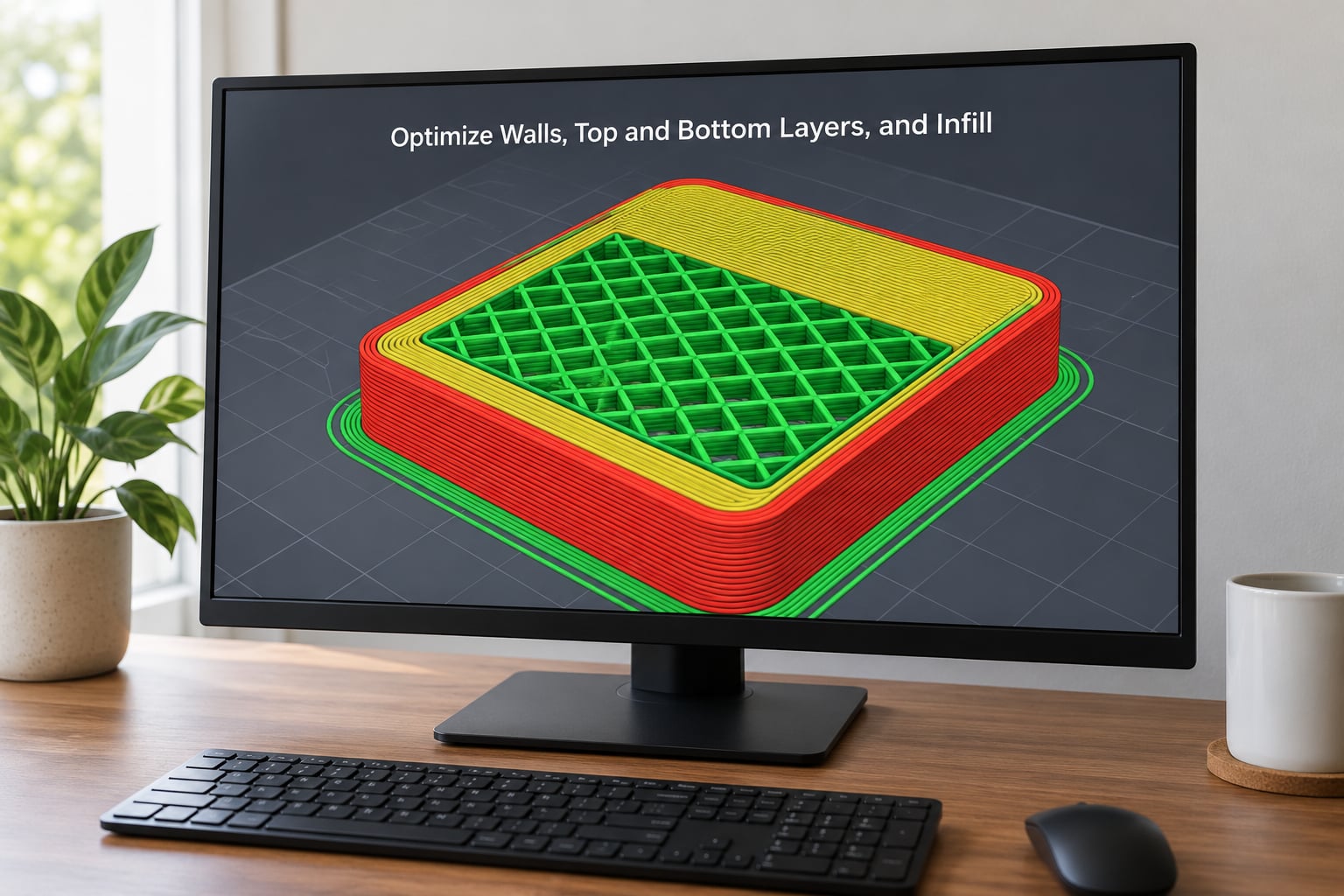
Most slicers let you set a different speed per feature. This is the single best structural trick available: the same print runs at one speed for what you see and another speed for what you do not.
- Infill and inner perimeters: double or triple the speed here. They are hidden, they are not load-bearing on their own, and they make up a large share of extrusion time.
- Outer wall: keep this slow. It defines the visible surface and the dimensional accuracy of the part.
- Top and bottom surfaces: slow to moderate. Fast moves across a top surface show as an uneven, slightly wavy finish.
- First layer: keep it slower than the rest. 20-30 mm/s is a common choice, and the adhesion gain is worth far more than the seconds saved.
- Bridges and steep overhangs: moderate, because part cooling decides whether they hold.
On infill itself, three settings do most of the work. Lowering density is obvious. Switching from a fine grid to a faster pattern such as cubic, gyroid or lightning removes small detail that costs time and adds nothing. And enabling variable infill lets you run low density in one region and high density in another, or add solid shells only near the load points, without splitting the model.
Check wall thickness against line width while you are in there. A 0.4 mm line width gives you a 0.4 mm layer, so a wall set to 1.2 mm lines up in three passes. A wall set to 1 mm with 0.4 mm lines forces a fourth, partial pass that adds time and leaves a visible seam line.
Reduce Travel, Retractions, and Wipe Moves
Travel moves print nothing. Combing the nozzle across the top of the part rather than flying through the air does not remove the move, but it turns each retracting jump into a short extruding one, and the saving adds up on tall models with many small features.
Raise travel speed freely. It is one of the few settings with almost no quality cost, limited only by how fast your machine can move without skipping steps. Slicers that allow more than one retraction or a larger wipe on corners can also reduce visible seam blobs at almost no time cost.
Do not blindly increase retraction distance. Too little and you ooze during travel; too much and the filament is ground inside the melt zone, which shows up as inconsistent flow and weaker layer adhesion. Retraction is set by filament type, extruder geometry and temperature, and it is not a speed setting at all — change it only if travel stringing is a real problem on your machine.
Seam placement is the quiet win. Putting the seam on a sharp corner, on the bottom face, or at a back edge of a display piece costs nothing and makes an otherwise visible line disappear. Many slicers also offer random or nearest-to-start-point seam placement, which is fine for functional parts and a poor choice for show pieces.
Use Temperature and Flow Tuning Selectively
A modest nozzle temperature increase lets the melt flow faster at a given pressure, so some materials tolerate a higher speed ceiling. It also raises stringing, warping and the chance of heat creep in the hotend on long prints. The temperature range that works for one spool of PLA tells you very little about the next one.
Flow calibration is the safer lever. If your extrusion width is correct and your flow multiplier is accurate, the nozzle lays down the right volume of material at a wider range of speeds. If flow is off, raising speed makes thin, ragged walls instead of faster walls. Run the calibration test for your chosen speed and temperature, then confirm it with a measured wall thickness.
Always follow the temperature guidance for the specific material and nozzle size in front of you, and compare like for like: one change, one test print, one measurement.
How to Speed Up 3D Printing Without Losing Quality in the Slicer
Every slicer does the same four things: profile duplication, machine limits, feature speeds and seam placement. The menu names differ between Cura, PrusaSlicer, OrcaSlicer and the Bambu Lab slicer, and they move between versions, so look for the concept rather than the exact label.
- Duplicate your working profile and make all changes in the copy. You now have a fallback you can return to in one click, which is the difference between experimenting and gambling.
- Set the machine limits honestly in the printer or machine profile before tuning anything else. Speeds and acceleration above the machine limit get silently clamped, which makes results impossible to interpret.
- Use feature speed overrides for infill, inner perimeter, solid infill, bridges, top surface and first layer. This is where most of the free time comes from.
- Enable variable speed printing if your slicer and firmware support it. Letting the firmware set speed per region from the G-code is a cleaner version of manual feature overrides.
- Set seam position and combing to cut travel time and hide the seam on a face you will not look at.
- Keep the quality settings fixed — line width, wall order, overlap — while you test speed changes, so you are measuring the speed effect and nothing else.
If you use Klipper, Pressure Advance replaces the older linear advance idea and compensates for the pressure lag in the melt zone, which lets you print corners and short lines at higher speed without bulging. Input Shaper compensates for the printer’s own resonance by shaping the motion command. Together they are the reason a tuned Klipper machine can hold high acceleration that would ring badly on the same hardware with Marlin defaults.
Improve the Model, Orientation, and Workflow
Time disappears into material the part does not need. A model reoriented so flat faces sit on the build plate needs far less support, and every gram of support removed is a gram not printed, not cooled and not broken off.
Run mesh repair before slicing. Non-manifold islands and duplicate faces produce toolpaths that make no structural sense and confuse the estimate. Over-designed parts — sharp internal corners the nozzle cannot reach, tiny holes below nozzle diameter, text thinner than a line width — force the slicer into long slow moves for geometry that will not print cleanly anyway.
Choose adhesion aids deliberately. A brim is usually cheaper than a raft and detaches more easily. A raft costs real time on a large footprint, and on a well-leveled bed for a low-profile part you may not need one at all.
For batch work, packing the build volume with parts that share a layer height is one of the largest available gains, because it fills Z while the machine would otherwise travel empty to the next item. Treat scheduling and packing as the next layer of work once your profiles are dialed in.
Run a Small Test Before the Final Print
Before committing a nine-hour job, print a shortened version of the same model. Trim the height to a few centimeters so you get the same feature types — exposed corners, thin walls, a bridge, infill, a top surface — in a fraction of the time.
Then judge it on four things: measure the same dimensions you recorded in your baseline, look at the corner surfaces under the same light for ringing, check the bridge and overhangs for sagging, and confirm the first layer stayed stuck to the plate. Accept the setting, revise it, or roll back to the baseline profile. Rolling back costs one click, which is the whole reason you made a copy.
Common Mistakes
Almost every ruined speed-up attempt comes down to one of these. The fix is always cheaper than the filament already in the failed print.
- Changing several settings at once. When the part looks wrong you have no idea which change caused it. Fix: one variable per test print, and keep the baseline profile intact.
- Starting from a maximum-speed preset. “Voron mode” style profiles are tuned for a specific machine, and applying one to a different frame ends in ringing and layer shifts. Fix: build up from the settings you already trust.
- Ignoring the first layer. A fast first layer that fails to stick wastes the whole print. Fix: keep it slower, and give the bed a wipe and a re-level between long jobs.
- Raising layer height past what the nozzle can support. Going far above roughly 75% of nozzle diameter produces underextruded, rough layers that slow you down later through nozzle snags and poor flow. Fix: 0.3 mm on a 0.4 mm nozzle, 0.45 mm on a 0.6 mm nozzle, then measure.
- Treating the preview as proof. A clean slicer preview says nothing about ringing, overhangs or layer adhesion. Fix: the small test print, always.
- Buying hardware before tuning software. A new board or hotend on an untuned machine produces the same defects, faster. Fix: exhaust the free settings first, then decide.
- Speeding up every feature equally. The outer wall, first layer and small details need headroom. Fix: feature-specific speeds.
To prioritize, here is how the changes rank. Time saving figures are typical for a mid-size FDM part and vary with geometry, so treat them as an order of work rather than a promise.
| Change | Typical time saving | Quality risk | Reversible |
|---|---|---|---|
| Raise layer height to 75% of nozzle | 15-30% | Low to medium | Yes |
| Drop infill and use variable infill | 10-40% | Low if loads are respected | Yes |
| Enable Input Shaper and pressure advance | 10-25% at equal quality | Low after tuning | Yes |
| Raise acceleration and junction deviation | 10-20% | Medium above the reliable limit | Yes |
| Feature speed overrides for hidden geometry | 5-15% | Very low | Yes |
| Reorient the model, cut support | 5-20% | None, if the part still fits its purpose | No, but repeatable |
| Calibrate flow for the chosen speed | Indirect | None | Yes |
| Larger nozzle, wider extrusion | 20-50% | Lower detail, weaker thin features | Needs different settings |
Material matters more than most guides admit. The numbers below are practical starting ranges for outer walls on a well-tuned 0.4 mm machine, not promises.
| Material | Reliable wall speed | Notes |
|---|---|---|
| PLA | 150-200 mm/s | Most forgiving; keep the nozzle cool enough to limit stringing |
| PETG | 100-150 mm/s | Needs good cooling; strings more as speed rises |
| ABS / ASA | 80-120 mm/s | Warping dominates, so an enclosure matters more than speed |
| TPU | 25-50 mm/s | Retraction must stay low; direct drive strongly preferred |
| PC | 60-100 mm/s | High heat, so keep the hotend well away from its limit |
Three tips worth more than the rest. If you do only one thing, tune acceleration and enable Input Shaper — that is free, and on a rigid machine it is where the biggest quality-neutral gain sits. If you do two things, raise layer height to 75% of your nozzle diameter, since fewer layers means less time at every speed. And keep a separate, slower profile for display pieces, so speed work never costs you the one model that has to look right.
Frequently Asked Questions
Can I use a fast print profile without losing quality?
A fast profile only keeps its quality if it was tuned on your machine and your filament. Presets built for a rigid, well-tuned frame with input shaping will ring and shift layers on a stock machine. A safer approach is to build your own fast profile from your proven settings: raise layer height, raise acceleration in steps, speed up infill and inner perimeters, and leave the outer wall and first layer where they are. Test the profile on a shortened model before a long job.
Should I increase layer height to make 3D printing faster?
Yes — it is usually the biggest single saving, because it directly reduces layer count. Stay near 75% of your nozzle diameter, which is 0.3 mm for a 0.4 mm nozzle and 0.45 mm for a 0.6 mm one. Beyond that, the nozzle struggles to lay a full line and you get rough, underextruded layers instead of a faster print. Check surface finish and measure wall thickness before going further, and remember that taller layers also make small details blunter.
Does a higher nozzle temperature allow faster 3D printing?
A modest increase can help some materials flow faster at a given pressure, which raises the speed ceiling slightly. The cost is stringing, warping, and more heat reaching the hotend on long prints. Temperature ranges are specific to the filament brand, colour and nozzle size, so follow the guidance for the spool in your hand. In practice, calibrated flow and good acceleration usually buy more speed than temperature does, and without a downside.
How much should I increase acceleration and jerk?
Raise them in small steps and watch corners, not the middle of straight lines. Community calibration usually lands around 2000-3000 mm/s² as a working baseline, and 5000-7000 mm/s² on a well-tuned machine with input shaping enabled. If the surface after a corner ripples, you have gone too high. Klipper-based firmware calls this junction deviation, and on Marlin-style firmware the equivalent control is jerk.
Does low infill speed make a 3D print faster?
No — lower infill speed makes prints slower, and infill is often the largest hidden block of time in a print. Two changes help instead: lower the infill density where the load allows, and give infill its own higher speed than the outer wall. Add variable infill so dense material appears only where stress actually goes. Keep enough solid shell around the perimeter that the part still handles real use.
How can I tell if a faster print still has acceptable quality?
Compare against your baseline on the same model and filament. Measure the dimensions you recorded before, look at exposed corners under the same light for ringing, and check bridges and overhangs for sagging. A shortened version of the model, a few centimetres tall, gives you all the same feature types in a fraction of the time. If anything regresses, roll back that one setting rather than lowering everything you already improved.
Conclusion
Record a baseline print first, so you know what quality looked like before. Then raise layer height to about 75% of your nozzle diameter, cut infill where the load allows, and push acceleration up in small steps with Input Shaper enabled if your firmware has it. Give the hidden geometry a higher speed and leave the first layer, outer wall and top surfaces where they are.
Test each change on a shortened version of the model, measure it against the baseline, and keep only what passes. One variable at a time is slower for an afternoon and much faster than a failed nine-hour print.