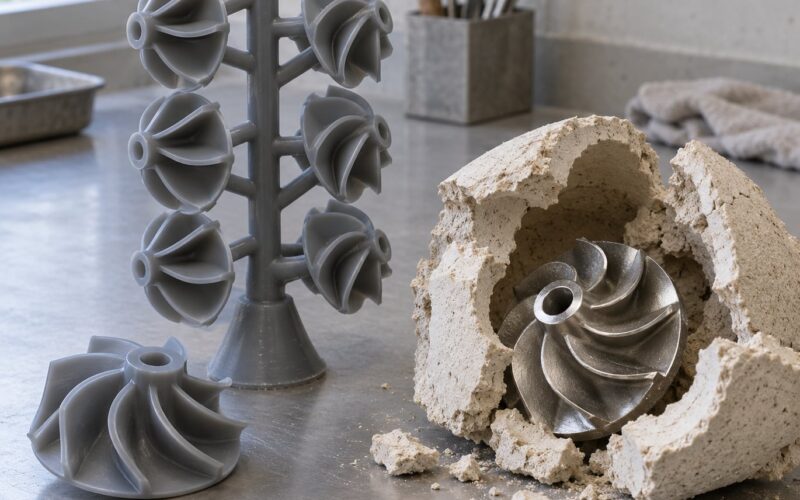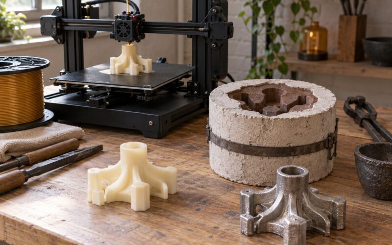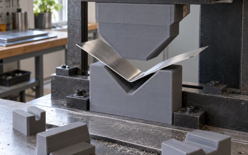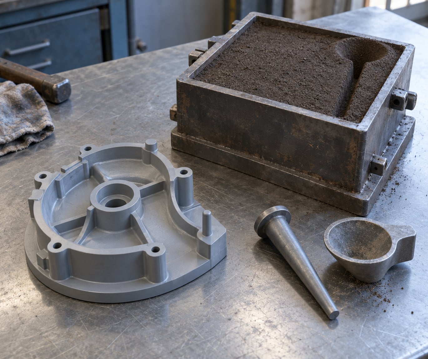
A 3D printed sand casting pattern is a plastic replica of the finished part that presses a cavity into sand, and molten metal poured into that cavity becomes the real part. You go from a CAD file to a printed, sealed pattern in an afternoon, press it into a flask, and pour. The whole run is a weekend project once you have the gear, and the three things printing buys you are no tooling cost, geometry you could never carve, and design changes that take minutes instead of weeks.
I’ve watched people get this wrong in the same three places: a pattern printed with no draft that tears the cavity out of the sand, a pattern scaled wrong so the casting comes out undersize, and a raw print with visible layer lines that transfers every one of them into the metal. None of that is hard to avoid once you know what to build into the model.
This guide is current for 2026 and covers FDM and resin printers, home flasks and small-shop equipment. Where I mention real numbers, they come from published foundry guidance or from hobbyists who have counted their pours, not from guesswork.
Table of Contents
- 1What You Need
- 2Step-by-Step: How to Use 3D Printing for Sand Casting Patterns
- 31. Define the Casting Geometry and Shrinkage
- 42. Create a Manufacturable CAD Model
- 53. Choose the Right 3D Printing Process
- 64. Slice, Print, and Check the Pattern
- 75. Remove Supports and Finish the Surface
- 86. Build the Sand Mold and Test the Setup
- 97. Pour Metal and Reuse the Pattern
- 10Common Mistakes
- 11Frequently Asked Questions
- 12What 3D printing material works best for sand casting patterns?
- 13Should I use FDM or resin for a casting pattern?
- 14How much shrinkage should I add to a casting pattern?
- 15Do I still need draft angle on a 3D printed pattern?
- 16How many molds can one 3D printed pattern make?
- 17Can a beginner safely pour molten metal at home?
- 18Conclusion
What You Need
The short version: CAD software, a slicer, a printer, a filament or resin, sand, a flask with matching cope and drag halves, a few hand tools, and safety gear that covers molten metal. The alloy you intend to pour decides most of the rest.
Design and slicing. Free parametric options like Fusion 360 or FreeCAD handle anything a pattern needs, including drafts and scale factors. A slicer such as PrusaSlicer or OrcaSlicer applies the shrinkage scale at print time, which saves you from editing the model twice.
Printer. For most home patterns an enclosed FDM machine with a rigid frame is enough. Resin printers give finer detail and a smoother pattern surface, which saves finishing time, but the resin route needs proper washing, curing and ventilation. Large FFF machines matter only when the part exceeds a desktop build volume.
Pattern material. This is where hobbyists argue, and the forum consensus is closer than the arguments suggest:
| Material | Flatness and rigidity | Finishing needed | Best use |
|---|---|---|---|
| PLA | Rigid, but bows more on big flat areas | Filler and primer; glues easily with CA | Beginners, one-off patterns, small parts |
| PETG | Prints flatter, dimensionally steadier than PLA | Filler and primer | Split patterns where parting-line flatness matters |
| ABS or ASA | Most rigid and heat-tolerant of the filaments | Can be solvent-welded into one solid piece | Larger or reusable patterns, in an enclosed heated chamber |
| Castable resin | Fine detail, brittle in thin sections | Wash, cure, seal thoroughly | Lost-wax burn-out patterns and jewelry-scale work |
One hobbyist on the Canadian Hobby Metal Workers forum reports roughly a hundred castings from printed patterns using nothing but cheap PLA, and PLA is the only filament he has used for the job. Other makers report PETG printing flatter, which matters when a split pattern has to seat without a gap. ABS and ASA need an enclosed heated chamber that most home printers don’t have, which is the real barrier to the solvent-welded route.
Sand and mold equipment. Green sand with bentonite is forgiving and free, but it collapses if you pack it loosely. Petrobond is oil- or resin-bonded silica sand: stronger, holds a thin wall, and gives a much better casting surface. You also need a flask in two halves, a tapered sprue pin, a pouring basin or small runner, vent wire, and a rammer or the heel of your hand.
Safety gear. Face shield rated for molten metal sparks, leather jacket and gloves for handling crucibles and ladles, a heat-rated face shield for pouring, and a shop vacuum with a HEPA filter. Work outside or with serious extraction. Metal fumes and burning pattern coatings in a closed room are how people get hurt, not the pour itself.
Step-by-Step: How to Use 3D Printing for Sand Casting Patterns
1. Define the Casting Geometry and Shrinkage
Start from the finished metal part, not the ideal shape. Metal shrinks as it cools, so the pattern must be made bigger than the target, and every surface the sand has to slide across needs draft.
The working numbers most foundries start from:
- Shrinkage allowance: add 2 to 3 percent to all dimensions for aluminium and most non-ferrous alloys. Different alloys shrink differently, so confirm the figure for your metal before you commit.
- Draft angle: 2 to 3 degrees on every surface parallel to the draw direction. Sharp features get a fillet instead of a bare corner.
- Parting line: pick the split point before you model anything else. It decides how many pieces you print and where the dowels go.
- Machining allowance: add 1.5 to 3 mm on faces that will be machined later, so you have metal to cut into.
- Fillets: round internal corners so sand doesn’t create a sharp void the metal can’t fill.
How you know it worked: measure the STL’s widest dimension, multiply by 1.02 or 1.03, and check that the result matches your shrinkage figure. Do it once, in the model, and never again.
2. Create a Manufacturable CAD Model
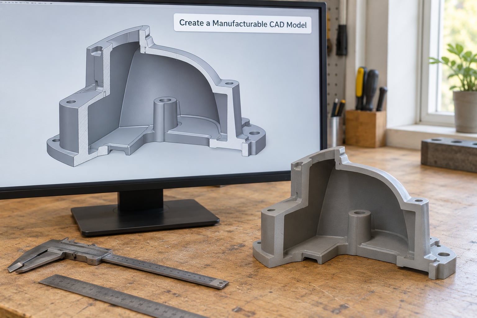
The pattern does not have to be a solid block of the part. Hollow it out so only the surfaces that touch sand carry wall thickness, and split it at the parting line into pieces that fit your build volume. A shell of a few millimetres is rigid enough and prints far faster than a solid.
Now the part every competitor page skips: model the hardware into the pattern. Add dowel pins and matching holes for a split pattern, so the two halves register the same way every time. Add rapping screws or a draw bolt pattern so you can lift the pattern straight out without levering it. Add a draw hole if you can reach one. These features cost nothing to add in CAD and save the casting.
Also model sprue, runners and vents directly into the pattern geometry, or at least mark where they will attach. Vents let trapped gas escape from the far end of the cavity; without them you get a short pour or a gas pocket.
How you know it worked: every surface the pattern must slide along has at least 2 degrees of draft, no face that sand touches is vertical, and the two halves share dowel and screw positions that line up in the preview.
3. Choose the Right 3D Printing Process
FDM prints a pattern from filament and is the default for most makers. Resolution is limited by layer height, but a 0.2 mm layer gives a pattern surface good enough for small castings after sealing, and the material is cheap and easy to finish.
Resin prints finer features and a smoother surface, so finishing takes less work, but resin is brittle, more expensive per litre and needs careful handling and a wash-and-cure station. It earns its place on intricate geometry or when surface finish matters more than durability.
The third option skips the pattern entirely: a printed sand mold, where the sand tool itself is printed, cured and assembled. That route removes pattern making and core boxes completely, but it locks you into a resin-bonded sand process, needs an industrial printer, and costs more per part at low volume. For a workshop printer and a weekend, printing the pattern is the sane choice.
How you know it worked: the process choice matches the accuracy you actually need. Hobby aluminium small castings do not need binder-jetted sand tooling.
4. Slice, Print, and Check the Pattern
Apply the shrinkage scale in the slicer rather than in the model, at 102 or 103 percent, so you keep one master file at true size. Then set the print for rigidity and finish, not for speed.
- Layer height: 0.2 mm or finer. Coarser layers give you layer lines in the casting.
- Infill: 100 percent solid. A sparse pattern flexes when you rap the flask and it floats in the sand before it packs.
- Walls: at least 1.5 to 2 mm on any surface that will be handled or supported.
- Orientation: lay the parting face flat on the bed. A printed face warps, and parting-line flatness decides whether the mold closes cleanly.
- Supports: keep them off the mold-forming surfaces. Anything you have to sand off is a defect you’ll chase later.
- Brim or raft for large flat prints to stop the corners lifting.
How you know it worked: no visible layer separation, no lifted corners, and a caliper check on the critical dimension shows the shrinkage scale landed where you intended. If the print bowed, reorient it rather than fighting the warp at the finishing stage.
5. Remove Supports and Finish the Surface
This is the step that decides your casting’s surface finish, and it’s the one most people try to skip. Pattern makers describe the same sequence without much variation: sand to 220 grit to knock down layer lines, fill the remaining valleys with body filler, spray high-build primer, wet sand the primer flat, then seal with shellac or a gloss lacquer.
Work in small passes. Filler shrinks as it dries, so two thin coats beat one thick one. Wet sanding the primer is what produces the almost glassy surface that releases from sand cleanly. Use water and a wet-dedicated grit so you’re not loading paper with plastic dust.
Seal every pore. Open channels in the pattern surface hold sand grains, and those grains become inclusions and rough patches in the casting. If you see bare plastic anywhere after sanding, seal again.
How you know it worked: run a fingernail across the surface and find nothing to catch, then re-measure the key dimensions. Filler and primer add material, and a pattern that’s now 1 mm oversize in one spot will print a casting that’s oversize there too.
6. Build the Sand Mold and Test the Setup
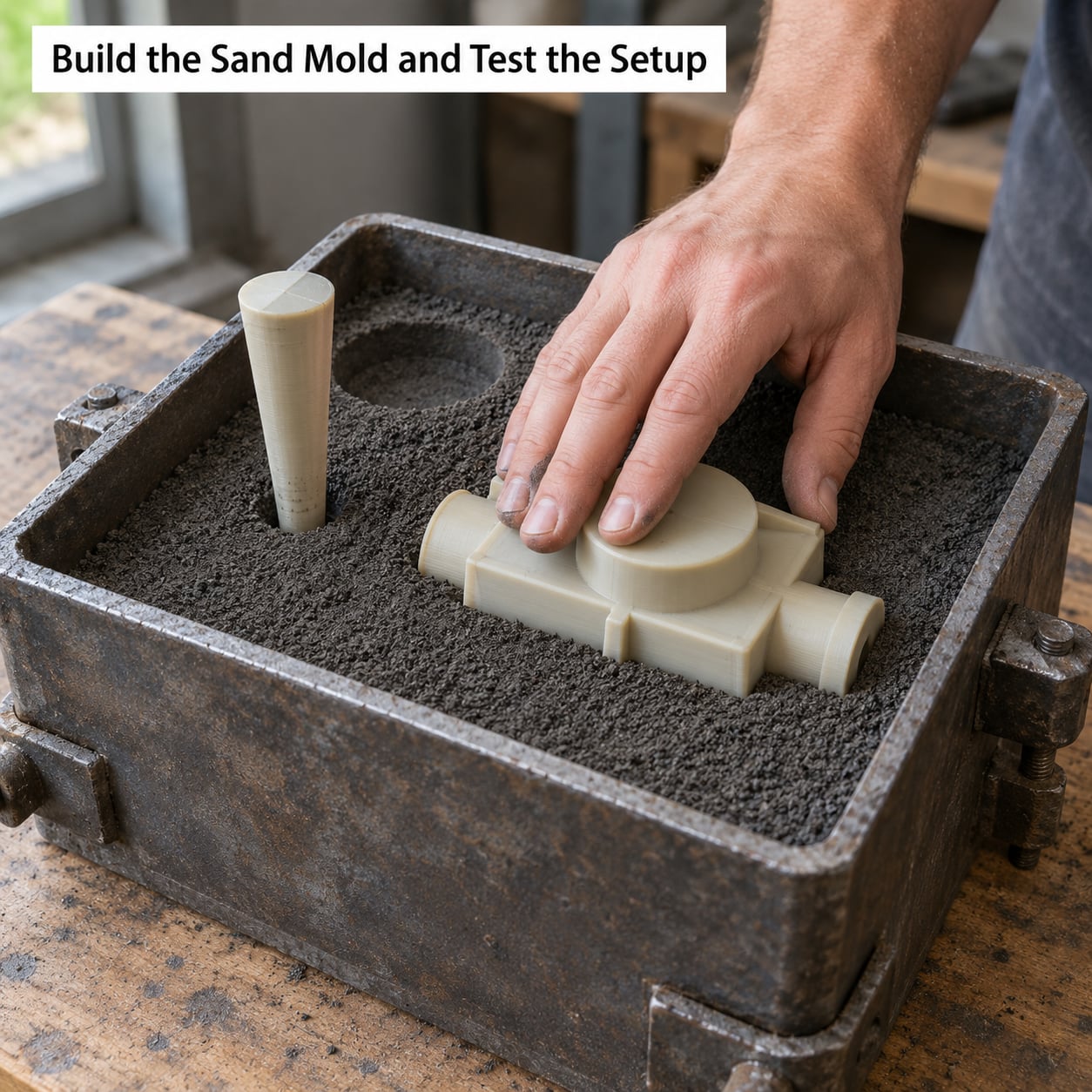
Set the drag half of the flask on a flat board and fill it with a couple of centimetres of backing sand, rammed lightly. Sprinkle facing sand over that, which is the layer that touches the pattern, and it’s the layer that determines surface quality.
Press the pattern into the sand, working from the far end toward yourself so air pushes ahead of it instead of being trapped under. Ram firmly around the pattern with the rammer or your palm. Pack the sand above the pattern’s top surface, level it off, and dust the parting surface with parting powder so the two halves don’t bond.
Lay the cope on, ram it the same way, then roll the flask or tap it lightly to settle the sand. Insert the tapered sprue pin in the drag before the cope goes on, and cut vent holes at the far end of the cavity with a thin wire. Lifting the pattern and drawing it back out is where you find out whether your CAD work paid off.
Draw it slowly, straight along the draw axis, without twisting. If the pattern resists or drags sand with it, stop and look for a zero-draft surface or an unfilleted corner.
How you know it worked: the pattern lifts out with light resistance and the cavity walls show no torn sand. Run a thin layer of aerosol chalk or release spray into the cavity and look for thin, continuous lines rather than bald patches and drag marks.
7. Pour Metal and Reuse the Pattern
Close the flask, add clamps or bolts, and set it on a flat, level surface away from anything that melts. For a first pour, aluminium is the metal to learn on: it melts around 1220 F and pours near 1300 F, needs less equipment, and forgives a lot of mistakes.
Preheat the metal and pour steadily without stopping. Skinny tapered sprues, as described in John Campbell’s Mini Casting Handbook, fill faster and cleaner than fat straight ones because metal moves through the narrow section faster than air can escape.
Let it cool, then shake out the sand and inspect the casting for flash, cold shuts, gas porosity and short fills. Now judge your pattern: if it came out with a clean cavity and no torn sand, it’s built to be reused.
A sealed pattern should make many molds; hobbyists report dozens of pours from the same printed half. Replace it when the surface starts losing its seal, when a layer line starts printing into the casting again, or when repeated rapping has cracked it. Wash it, dry it fully, store it flat and out of sunlight so the parting face doesn’t bow.
Common Mistakes
Nearly every failed first pour traces back to one of these, and the symptom tells you which.
| Symptom | Cause | Fix |
|---|---|---|
| Pattern tears the cavity, drags sand with it | No draft on a sand-contact surface, or sharp unfilleted corners | Add 2-3 degrees of draft and fillets in CAD; sand and seal the print |
| Pattern floats or shifts before packing | Too light, or too little sand under it | Print solid at 100 percent infill and bury the pattern deeper in backing sand |
| Parting line leaks sand or the cope won’t seat | Bowed parting face from a flat-printed PLA part | Print in PETG, add a brim, or print the parting face on the bed with a raft |
| Pattern flexes, holes come out oval | Thin walls or low infill | Minimum 2 mm walls, 100 percent infill, hollow only the interior of the part |
| Sand mold collapses in the flask | Loose packing, or plain green sand on a thin wall | Ramm harder, use Petrobond or chemically bonded sand for thin sections |
| Short pour, cold shut at the far end | Trapped gas, no vents | Cut vent holes at the high point of the cavity, use a tapered sprue, pour without stopping |
| Rough casting surface, visible layer lines | Raw print sealed only lightly, or coarse layer height | 0.2 mm layers, full sand-fill-primer-seal sequence |
| Pattern sticks in the mold | Unsealed print, sand too green, no parting agent | Seal fully, add parting powder or release spray to the pattern face |
| Fumes, headaches, smoke in the workshop | Melting metal or burning coatings in poor ventilation | Work outside or with extraction, wear the shield and gloves, never pour indoors without a hood |
A pre-cycle check worth running every time: pattern sealed and dry, dowels and screws present and aligned, parting powder applied, sprue and vents in place, flask level, and the area around it clear for twenty minutes of pouring. That list catches more failures than any single trick in the workflow.
Frequently Asked Questions
What 3D printing material works best for sand casting patterns?
PLA is the most common starting point because it prints easily, is cheap, and glues well with CA for building a bigger pattern from pieces. PETG prints flatter and holds dimensions steadier, which matters on split patterns where a bowed parting face leaks sand. ABS and ASA are the most rigid and can be solvent-welded into one piece, but they need an enclosed heated chamber. Whichever you pick, seal the print before it goes near sand.
Should I use FDM or resin for a casting pattern?
Use FDM unless surface finish or fine detail decides it. FDM gives a cheap, tough, easy-to-finish pattern at 0.2 mm layers, which is enough for most hobby castings. Resin prints finer and smoother, so you spend less time filling and priming, but it costs more per volume, is brittle in thin sections, and needs washing and curing. The skill you already have matters more than the theory here.
How much shrinkage should I add to a casting pattern?
Add 2 to 3 percent to all dimensions for aluminium and most other non-ferrous alloys, which is the range most hobby foundries work from. Apply it as a slicer scale factor so you keep one master CAD file at true size. Different alloys and different mold materials shrink by different amounts, so check the figure for your specific metal rather than assuming it transfers.
Do I still need draft angle on a 3D printed pattern?
Yes. Printing removes the need to model around a cutter, but it does not change the fact that sand has to slide along the pattern surface to release it. Give every sand-contact surface 2 to 3 degrees of draft on the draw side, and fillet sharp internal corners. A vertical face will still drag sand and tear the cavity, which is the most common reason a printed pattern fails.
How many molds can one 3D printed pattern make?
A properly sealed pattern can make dozens of molds; hobbyists report large casting counts from the same printed halves. Your limit is surface condition rather than a number. Replace it when the seal breaks down and the casting surface starts showing layer lines again, when rapping has cracked a thin wall, or when the parting face has warped. Wash and dry it after each use and store it flat.
Can a beginner safely pour molten metal at home?
Pouring is doable but it is real foundry work, not a kitchen project. Aluminium is the forgiving first metal: it melts near 1220 F and needs the least equipment. You need a face shield rated for sparks, leather gloves and jacket, a heat-rated shield for pouring, proper extraction or outdoor space, and clear ground for twenty minutes around the pour. Take a shop course before handling bronze or anything above aluminium.
Conclusion
The first thing to get right when you use 3D printing for sand casting patterns is the model, not the printer. Pick your metal first, because that fixes the sand, the pour temperature and the shrinkage figure you’ll design to. Then model one small test pattern with 2 to 3 degrees of draft, a scale factor of 1.02 or 1.03, and dowels and draw screws modelled in before you print anything. Print it solid at 0.2 mm layers, take it through the full sand-fill-primer-seal finish, and make one test mold to check the cavity before you scale up to the real part.
Once that one casting comes out clean, the pattern route is genuinely fast. Design changes that used to mean weeks of pattern work now take an evening.