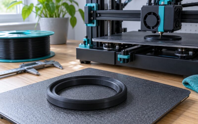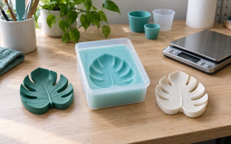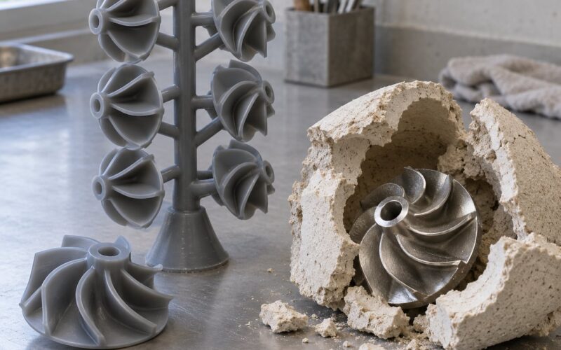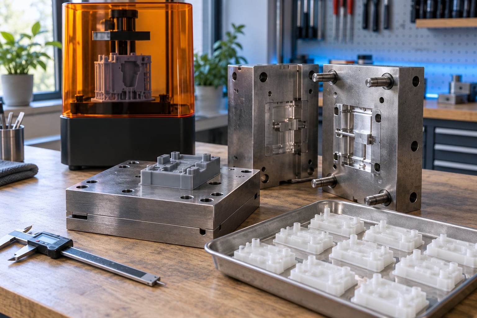
Learning how to make injection mold inserts with 3D printing comes down to six moves: model the cavity, slice it, print it, finish it, fit it into a rigid frame, and mold parts until it fails. A printed insert is not a replacement for production steel tooling, but it turns a multi-week wait and a heavy setup cost into a couple of days, which is enough time to test a part in its real material before anyone cuts tool steel.
The catch is that inserts fail predictably if you skip the boring parts. Mold temperature, draft angle, layer height and wall thickness decide whether you get hundreds of good shots or a cracked insert after the second one. Most first attempts fail on shot number two, which tells you the cavity never filled properly on shot one.
If you have a resin printer, a mold frame and a way to heat and inject plastic, you can be molding functional parts this weekend. If you are still shopping for hardware, start below with the short version of the workflow and then the full seven steps.
Table of Contents
- 1What You Need to Make Injection Mold Inserts With 3D Printing
- 2Software for the cavity
- 3Printer and process capability
- 4Material samples
- 5Frame, fasteners and alignment
- 6Inspection and finishing
- 7Step-by-Step
- 8Step 1: Define the Insert Function and Constraints
- 9Step 2: Design the Insert and Mold Interface
- 10Step 3: Choose a 3D Printing Process and Material
- 11Step 4: Validate Clearances, Wall Thickness and Supports
- 12Step 5: Print the Insert
- 13Step 6: Inspect and Post-Process the Printed Part
- 14Step 7: Install, Test and Iterate
- 15When to move to machined tooling
- 16Common Mistakes and How to Fix Them
- 17Designing without draft or clearances
- 18Choosing a polymer that softens too early
- 19Printing in an orientation that puts supports on the cavity
- 20Ignoring heat and cooling
- 21Trapping supports and uncured material
- 22Using insufficient infill and thin cross sections
- 23Leaving holes rough and unreamed
- 24Not verifying shrink compensation
- 25Using inadequate fasteners
- 26Skipping the mold trial
- 27Tips worth remembering
- 28Frequently Asked Questions
- 29Can you make injection mold inserts with a regular FDM printer?
- 30What is the best 3D-printing material for injection mold inserts?
- 31How much shrinkage and tolerance allowance should I use for a printed insert?
- 32Can 3D-printed inserts include cooling channels?
- 33Are 3D-printed inserts suitable for production molds?
- 34How do I calculate the required strength and heat resistance of an insert?
- 35Conclusion
What You Need to Make Injection Mold Inserts With 3D Printing
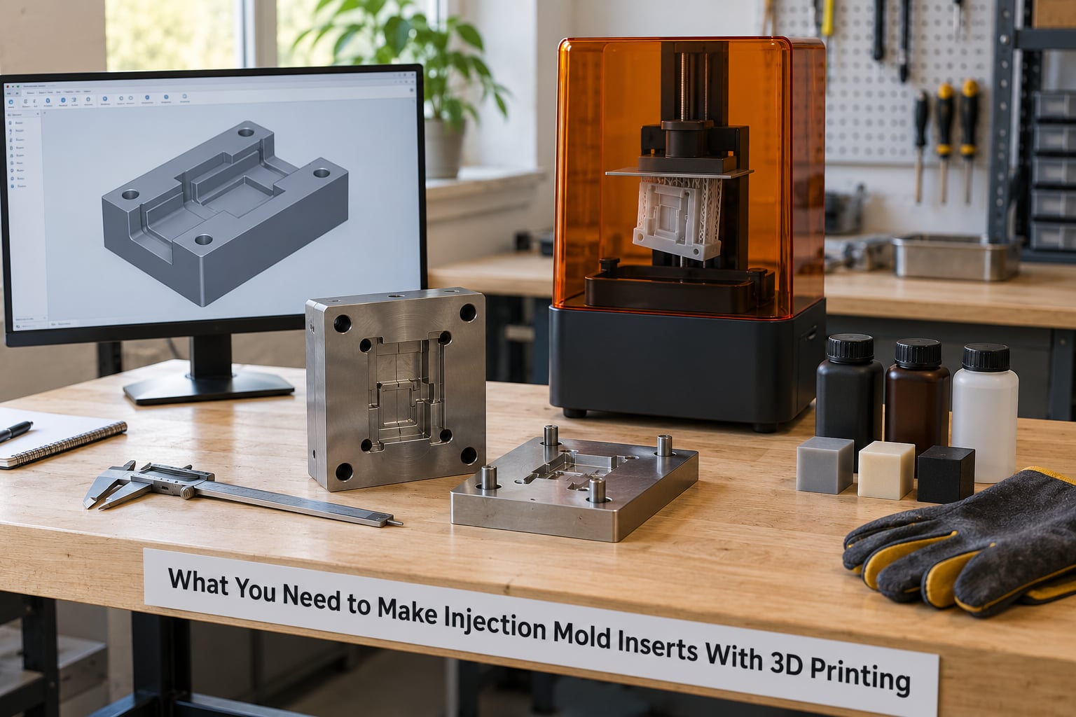
A 3D printed injection mold insert is the replaceable core that forms the cavity. The mold base or frame around it is the rigid structure that takes the clamping load and stays dimensionally stable. Print the core, buy or machine the frame, and never ask the plastic to do a frame’s job.
Software for the cavity
Any solid modeling package that can export STEP or STL will work: SolidWorks, Fusion 360, Inventor, Onshape or a free option like FreeCAD. You need parametric control over draft, offsets and hole patterns because you will adjust them after the first print, and you need a boolean tool to cut vents, runners and cooling passages.
Printer and process capability
SLA, DLP or MSLA resin printing handles most insert work, because the surface finish transfers directly to molded parts and layer height can go down to 50 microns. FDM works for simple inserts printed in high-temperature PLA, but you give up surface finish and get visible layer lines on every part.
Plan for a heated build area if your insert is larger than roughly 150 mm across. Resin prints that size put real stress on the FEP film during peel-off, and warped inserts will not seal against the frame.
Material samples
Buy small samples of candidate tooling resins or filaments before committing to a full spool or bottle. You need the material’s heat deflection temperature under load to sit above your mold temperature, and you need to know the glass transition temperature to understand where the part starts to lose stiffness.
Frame, fasteners and alignment
Prefabricated aluminum mold frames exist for this exact purpose and cost far less than building your own. Add shoulder bolts or cap screws sized to your printed insert, plus dowel pins or alignment pins if you want the insert to return to the same position every time you pull it.
Inspection and finishing
Digital calipers are non-negotiable; you will measure the cavity depth, the fit in the frame pocket and the ejector holes. Add a reamer set, wet sandblasting equipment with a fine abrasive, a diamond file or burr, and heat-resistant gloves plus eye protection for the molding trials.
How heavy your requirements get depends on three variables. Insert size drives frame thickness and printer capability. Production volume drives whether a printed insert is even viable, since it will not reach the shot life of steel. And mold temperature drives material choice more than anything else, because that is the number the insert has to survive.
Step-by-Step
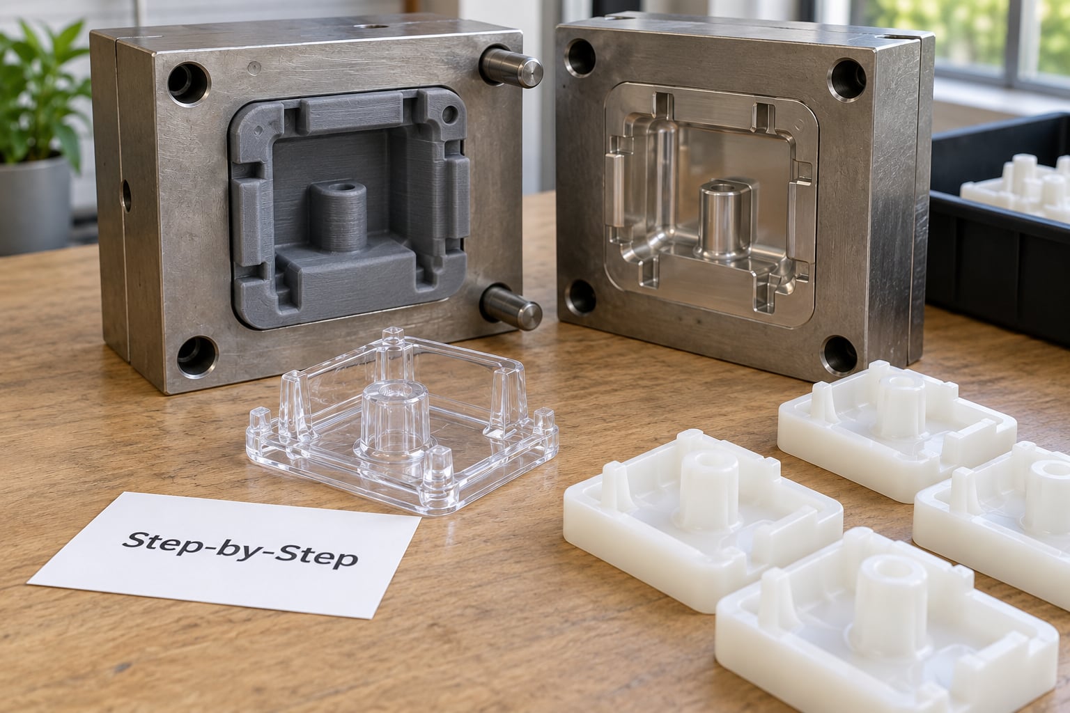
Step 1: Define the Insert Function and Constraints
Write the requirements down before you open your CAD package. You need the molded feature itself, draft, surface finish, tolerance, expected cycle life, the injection material, the mold temperature, cooling requirements, the insert interface with the frame, and the production volume you actually need.
Mold temperature is the constraint people skip and then regret. Polyamides are molded around 270 C, which will destroy most photopolymer tooling resins within a handful of shots. Polypropylene, TPE and POM run far cooler and are the realistic targets for a printed insert.
Also decide now whether this is a functional prototype, a pilot run, or a bridge to production. Prototype inserts can tolerate a rough surface finish. Pilot runs cannot, because your customer will be holding the part.
Step 2: Design the Insert and Mold Interface
Modeling the insert means drawing the negative of the part with enough allowance for everything that will happen to it. Uniform wall thickness comes first, typically around 10 mm nominal for a printed insert, because thin cross sections cool unevenly and print badly. Vary wall thickness gradually with ribs rather than abrupt steps.
Draft is the number that decides whether parts eject cleanly. One degree per inch of depth is the rule most moldmakers quote, so a 25 mm deep feature wants about 1 degree. Draftless walls will scrape, mark the part and stall ejection, and no amount of mold release fixes geometry.
Ribs and gussets should be 40 to 60 percent of the adjacent wall thickness. Add generous radii on every internal corner, since sharp internal corners concentrate stress in both the printed insert and the molded part.
Then build the interface: the parting line, ejector clearance holes, fastener or screw holes, a keyed pocket so the insert drops in the same way every time, and screwdriver notches so you can extract it without marring the cavity. Vent holes around 0.1 mm deep at the end of fill are what keep parts from burning or flashing at the last few millimeters. Runners around 0.5 mm diameter feed a small gate directly into the cavity for short-run work.
Conformal cooling channels are possible in a printed insert if your process can clear the resin from inside them, but sealed channels that trap resin will split under injection pressure. Open-topped channels that you later seal with a printed lid are the safer route.
Step 3: Choose a 3D Printing Process and Material
Match the process to how many parts you need and how hot the molding runs. This is where most 3D printed injection mold insert projects succeed or quietly fail, because people choose resin for its surface finish and ignore the temperature.
| Process | Best fit | Watch out for |
|---|---|---|
| SLA / DLP / MSLA resin | Functional prototypes, pilot runs, smooth cavity surfaces, complex internal geometry | Brittle resins crack at high mold temperatures; large prints need suction and stress management |
| FDM high-temperature filament | Simple inserts, low-volume work, printers already on hand | Layer lines mark the molded part, weaker layer adhesion, slower cycles |
| SLS / MJF | Complex geometries with no support strategy to plan | Porous surface, rough cavity, limited detail on critical faces |
| Metal additive manufacturing | Production-intent inserts and conformal cooling in hard alloys | Post-processing and machining time erode the lead-time advantage |
| Dissolvable sacrificial tooling | One-shot patterns where the tool is dissolved instead of removed | Alkaline dissolution takes 12 to 48 hours and consumes resin |
For polymer inserts, pick a material rated well above your mold temperature and accept that a printed insert will deform gradually over cycles. Print a coupon with the same settings, hold it at mold temperature for the length of a cycle, and measure it. That test beats any datasheet guess.
Step 4: Validate Clearances, Wall Thickness and Supports
Accurate design for manufacturing is what separates a printable insert from a failed one. Printers drift, polymers shrink during cooling, and finishing removes material, so every dimension needs deliberate allowance.
Print a calibration coupon first: a block with a hole, a slot and a step, printed in the same orientation and with the same settings as the real insert. Measure it, and use the result to set your shrink compensation rather than a value from a generic guide.
Add finishing allowance on cavity surfaces you intend to sand or blast, and add extra clearance wherever the insert meets the frame. A 0.2 to 0.3 mm gap between insert and frame gives you room to shim and to account for post-processing distortion.
Plan supports as a design feature rather than an afterthought. Drain holes at the low point of every support island prevent trapped resin or purge from weakening the tool. Add sacrificial features, such as tabs you break off after printing, so the insert is not pried apart at a critical corner.
Step 5: Print the Insert
Orientation matters more than any slicer toggle. Printing the cavity face flat on the build platform removes supports from the surface that matters most and puts every layer line on the part’s underside rather than its walls.
Chamfer the edge that touches the platform so the print can be removed without peeling, and add alignment pins so the insert registers the same way on every reprint. Around 50 micron layers is a common starting point for resin inserts, since the step between layers shows up directly on the molded part.
Watch for the failure modes that show up on the printer, not the mold. First-layer adhesion problems lift corners, which is why a brim and a clean, level platform matter more than slicer profiles. Warping and delamination in filament prints usually mean insufficient chamber heat or poor layer bonding. In resin prints, look for voids that mean under-exposure and trapped fluid that means incomplete drainage.
Nobody has one universal profile for every machine. Change one variable at a time between test prints and keep the settings file with the CAD model, so the next revision is a small edit instead of a fresh experiment.
Step 6: Inspect and Post-Process the Printed Part
Start by removing supports carefully with flush cutters and a deburring tool, working from the cavity outward so a stray nick never lands on a molding surface.
For resin, wash the part, then fully post-cure it under UV or in a curing chamber until it reaches full stiffness. Under-curing is common and shows up later as a cavity that gradually distorts under heat. Clean the part after curing, since residual resin and support scars become flash points.
Measure critical dimensions with calipers against your post-print expectations. Check hole positions, cavity depth and the frame pocket fit before you cut anything.
Wet sandblasting with a fine abrasive takes the resin gloss off the cavity and gives molded parts a matte finish. Ream ejector holes and fastener holes by hand so they take bolts cleanly. Then hand-fit the insert into the frame with shims or shim stock, which is faster than trying to make the print fit perfectly on the first attempt.
Step 7: Install, Test and Iterate
Seat the insert, run your fasteners to a consistent torque, and confirm the parting line closes with no daylight. Use mold release only as specified for your process, since residue on cavity surfaces transfers to molded parts.
Run low-pressure trials first: modest injection pressure, short hold, conservative melt and mold temperature. Inspect the first few parts for short fills, flash, weld lines and sink marks. Short fills on shot one usually mean venting or gate problems, not a resin problem.
Then push toward production settings and log the shot count each time. Knowing when to retire the insert matters more than squeezing one extra shot out of it, because a cracked insert can damage the frame or the press.
This table is the honest expectation-setting step. Shot life is dominated by molding temperature and the molded polymer, not by print quality.
| Molded polymer | Typical mold temperature | Realistic shot life for a printed insert |
|---|---|---|
| Polyamide (PA) | Around 270 C | About 10 shots; often fewer |
| Polypropylene (PP) | Moderate | Tens to low hundreds of shots |
| Thermoplastic elastomer (TPE) | Moderate to warm | Tens to low hundreds of shots |
| Polyoxymethylene (POM) | Moderate | Hundreds of shots, with gradual deformation |
Document every failure with a photo and a shot count. That log is what tells you whether to change the design, the material, the print settings or the process parameters, and it shortens the next iteration to a single evening.
When to move to machined tooling
Switch to aluminum or steel when the printed insert starts deforming enough to affect part dimensions, when cycle time becomes the bottleneck, or when you need the same part in a material that molds too hot for printed tooling. Tool steel inserts deliver hundreds of thousands of shots and hold dimensions far longer, so treat printed inserts as a deliberate bridge, not a permanent answer.
Common Mistakes and How to Fix Them
Designing without draft or clearances
Draftless walls and zero-clearance fits are the two most common self-inflicted failures. Parts scrape, inserts bind, and the frame takes the load. Fix: one degree of draft per inch of depth, 0.2 to 0.3 mm clearance at the insert-to-frame interface, and a printed coupon to measure your actual dimensional drift before you commit to full dimensions.
Choosing a polymer that softens too early
Makers routinely pick a resin for its finish and then mold polyamide into it. The insert softens, creeps and distorts within a few shots. Fix: match the material’s heat deflection temperature under load to your mold temperature with real margin, and run a coupon at temperature before printing the whole insert.
Printing in an orientation that puts supports on the cavity
A cavity printed upward collects support scars that become flash and roughness on every molded part. Fix: print the cavity face flat on the platform, chamfer the base edge, and orient ribs and walls so layer lines run along walls rather than across them.
Ignoring heat and cooling
An insert that cannot shed heat gives you long cycle times and dimension drift that grows shot by shot. Fix: put real cooling into the design early, where you can reach it, and accept that open channels printed into the tool plus a printed cover seal better than sealed internal channels full of resin.
Trapping supports and uncured material
Unsupported islands hold resin, and under-cured resin stays soft. Both weaken the tool in ways that only appear under injection pressure. Fix: design drain holes, wash and post-cure fully, then re-check critical walls by hand for stiffness before fitting.
Using insufficient infill and thin cross sections
Thin printed walls lose stiffness as the material heats, and that is when inserts crack. Fix: keep walls near 10 mm nominal, use solid or near-solid infill for load-bearing walls, and add ribs at 40 to 60 percent of wall thickness instead of thinning the wall.
Leaving holes rough and unreamed
Printed ejector holes and fastener holes come out slightly oval and undersized. That is enough to push an ejector sideways and damage the insert. Fix: ream every hole by hand, then check fit with the actual fastener before installing.
Not verifying shrink compensation
Applying a generic shrink factor to a printer that has never been calibrated guarantees cavity dimensions that are simply wrong. Fix: print a calibration coupon in the real orientation, measure it, and store the numbers in the CAD template as your starting compensation.
Using inadequate fasteners
Plastic threads strip, and a loose insert shifts under clamping load. Fix: use shoulder bolts or cap screws with a thread-embedding insert if you are using threaded fasteners, and mark torque settings so every reassembly is identical.
Skipping the mold trial
Moving straight from print to production settings wastes good prints. Fix: run low-pressure trials, inspect the parts, change one variable at a time, and keep a written log. The person who molds parts will thank you.
Tips worth remembering
Print the insert, machine or buy the frame, and never print a whole large mold for a metal frame. Keep a copy of the CAD with its settings file attached so a correction is a small change rather than a new project. Iterate on the model the same day and reprint overnight, which is the real advantage over waiting on a machined correction. And treat any forum claim of shot life as a starting point, not a spec, because your part geometry, resin and mold temperature all move that number.
Frequently Asked Questions
Can you make injection mold inserts with a regular FDM printer?
Yes, for low-volume work. Print the insert in high-temperature filament, keep walls near 10 mm, print the cavity face flat on the build platform, and expect layer lines on every molded part. Resin printing is still better for cavity surface finish and tighter detail. FDM is a sensible choice when you already own the machine and need a functional batch rather than presentation parts.
What is the best 3D-printing material for injection mold inserts?
A rigid tooling resin or high-temperature filament whose heat deflection temperature sits well above your mold temperature. If you are molding polypropylene, TPE or POM, that is achievable. Polyamide around 270 C will destroy most printed tooling in about ten shots. Always test a coupon at molding temperature before printing the full insert.
How much shrinkage and tolerance allowance should I use for a printed insert?
There is no universal number, which is why you print a coupon. Measure a calibration block with a hole, a slot and a step in the real orientation and settings, then use those results as your shrink compensation. Leave 0.2 to 0.3 mm clearance where the insert meets the frame, plus finishing allowance on any cavity surface you plan to sand or blast.
Can 3D-printed inserts include cooling channels?
Yes, and printing them is one of the strongest arguments for additive tooling. The catch is clearing the material: sealed internal channels often trap resin that later splits under injection pressure. Open-topped channels covered with a printed lid are the safer route. Keep the channels large enough to clean and re-test flow before you install the tool.
Are 3D-printed inserts suitable for production molds?
They are suitable for pilot production and short runs of tens to a few hundred parts, not for volume programs. Expect roughly ten shots in polyamide and hundreds with gradual deformation in polypropylene, TPE or POM. Move to aluminum or steel when dimensions drift, cycle time becomes the bottleneck, or the molded material runs hotter than printed tooling can survive.
How do I calculate the required strength and heat resistance of an insert?
Start from the molded polymer and its mold temperature, then select a material whose heat deflection temperature under load exceeds that figure with real margin. Check strength against injection pressure over the cavity’s projected area, not just wall thickness. The fastest reliable answer is empirical: hold a printed coupon at mold temperature for a full cycle and measure it.
Conclusion
Start by writing down the insert’s job: what it forms, what temperature it has to survive, how many parts you need and how it bolts into the frame. Verify your clearances with a printed coupon, then pick a material and process that match that temperature rather than the one that prints nicest.
Print the cavity face flat, finish it properly, hand-fit it, and run low-pressure trials before you touch production settings in 2026. Keep the shot log. When the log tells you the insert is done, that is when machined tooling starts.