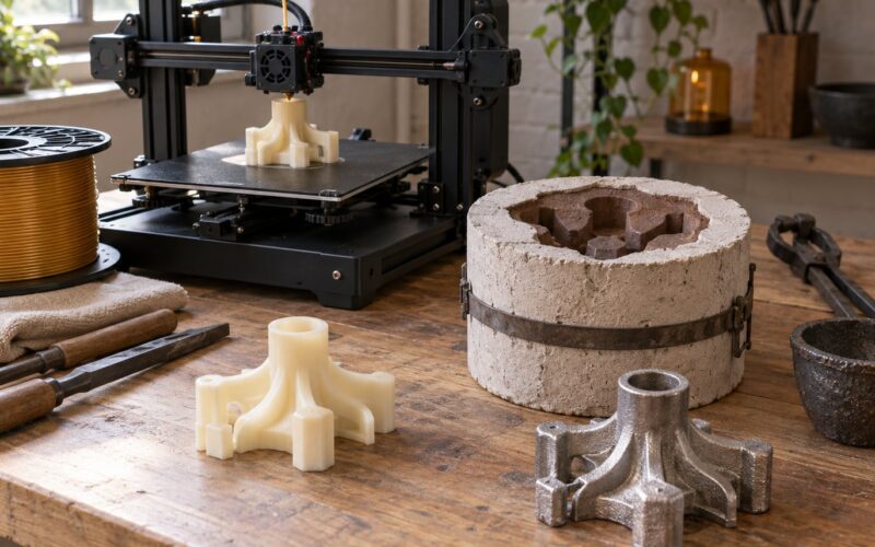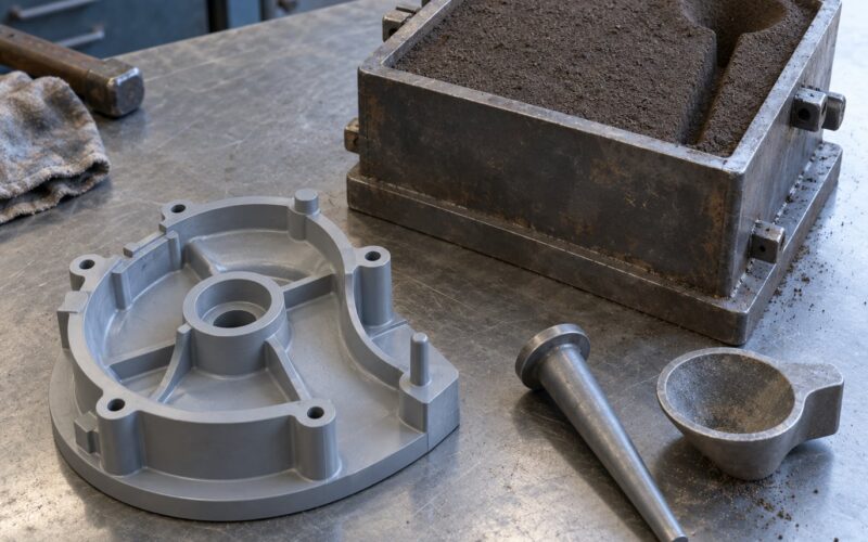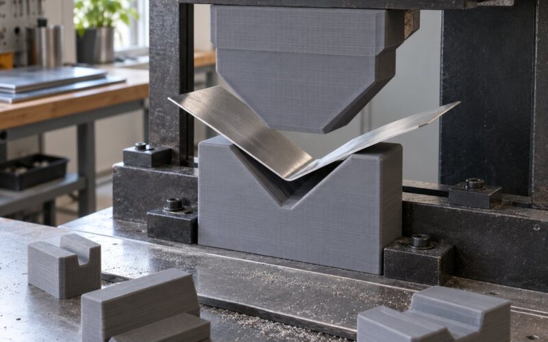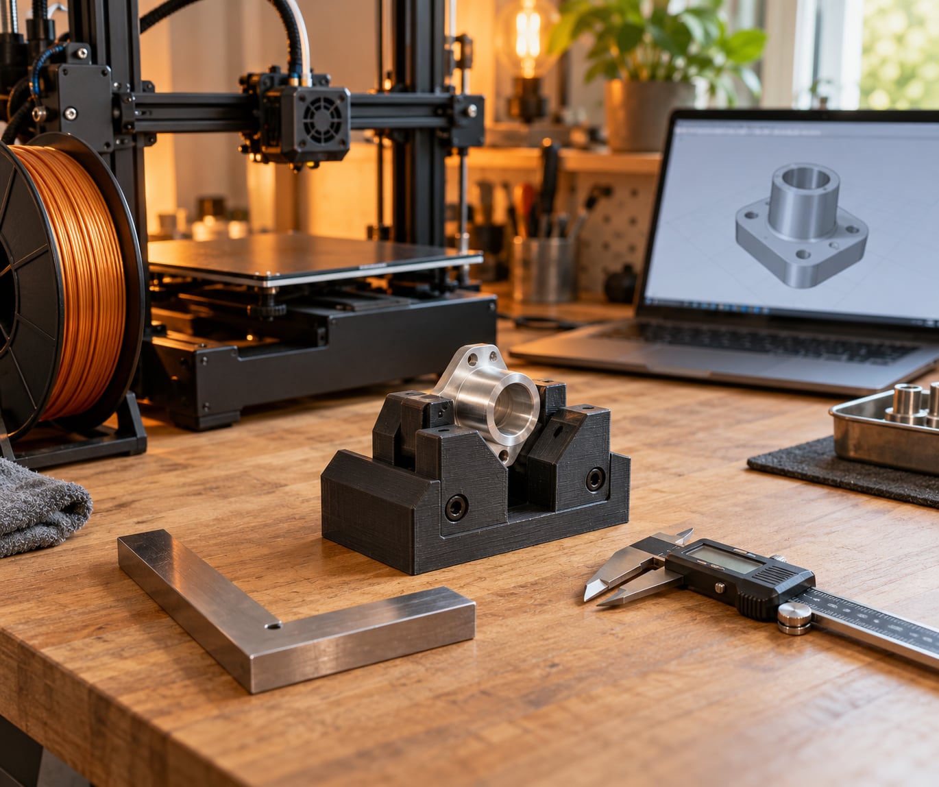
To use 3D printing for jigs and fixtures, model the part you already have, design a holder that touches it at a few stable points, then print in a material matched to the load and heat. Most of the work happens before the printer starts: measuring the real workpiece, leaving room for your printer’s dimensional error, and printing a cheap test fit first. A useful drill guide or clamp takes an afternoon and about 40 grams of filament.
The reason people print their own is simple. A store-bought jig is rarely the size you need and almost never fits the way your part does. One woodworker on r/woodworking described replacing loose, oversized store-bought mitre boxes with simple printed versions, and then noted how much time that saved on later projects. Tooling is a good use of additive manufacturing because jigs are small, low-volume, geometry-heavy and cheap to iterate on.
Table of Contents
- 1What You Need to 3D Print Jigs and Fixtures
- 2Step-by-Step
- 31. Define the Part and the Repeatable Task
- 42. Measure the Workpiece and Choose References
- 53. Design the Jig or Fixture in CAD
- 64. Select the Material and Print Settings
- 75. Slice and Print for Accuracy
- 86. Finish, Assemble, and Test the Printed Jig
- 97. Document and Improve the Fixture
- 10Common Mistakes When 3D Printing Jigs and Fixtures
- 11Frequently Asked Questions
- 12What is the best material for 3D print jigs?
- 13How do you get accurate fits from a 3D printed jig?
- 14Are 3D printed jigs strong enough for shop use?
- 15Can you 3D print fixtures for welding or other high-heat work?
- 16What should I print first?
- 17When is 3D printing the wrong way to build a jig?
What You Need to 3D Print Jigs and Fixtures
You need very little to start. The list below is what ends up in the drawer after your first few printed jigs.
- Digital calipers and a good straightedge or machinist square for measuring the real part.
- The physical workpiece itself. This is the single most important item, and it is not optional.
- A photo or a scan from a phone with a scale reference, or a 3D scanner if you have access to one.
- CAD software such as Fusion 360, SolidWorks, Onshape or FreeCAD, plus a mesh tool like Meshmixer for quick shapes.
- An FDM printer with a heated bed. Resin printers work but add handling and safety steps.
- Material: PETG for general shop use, ASA or nylon for heat, TPU for soft contact surfaces.
- Hardware: M3 or M4 heat-set inserts, machine screws, shoulder bolts, springs, magnets, T-nuts or T-track.
- Safety gear: safety glasses, a dust mask or extraction for abrasion and plastic dust, and nitrile gloves for handling finished or plated parts.
Metal reinforcement is worth adding when the jig sees impact, clamping force or heat that plastic alone will not survive. The common hybrid is a printed body with steel shoulder bolts in heat-set inserts, or a printed locator plate bolted to an aluminium base. Add brass or steel bushings anywhere a drill bit or reamer passes through, because a printed guide hole wears out in a way a hardened bushing does not.
Step-by-Step
1. Define the Part and the Repeatable Task
Start by naming the operation, not the object. “Holding the bracket while I drill two M5 holes” tells you what to build. “A holder for brackets” does not.
Write down three things before opening CAD: how the part must be located, how much clearance the process tolerates, and how many times a day the jig gets used. That last number decides material. A jig used twice a month can be PETG or even PLA. One used all day at a clamp is a different part entirely.
Decide whether you are building a jig, which guides a tool, or a fixture, which holds the workpiece without guiding anything. Fixtures generally carry more load and need stiffer locating surfaces. If you are unsure, treat any setup where a tool enters the material as a jig and give the guide extra thickness. Everyone working out how to use 3D printing for jigs and fixtures hits this split early: plastic carries the geometry, metal carries the load.
2. Measure the Workpiece and Choose References
Measure the part in your hand, not the drawing. Prints vary and drawings are often optimistic, so the physical part is your reference.
Take a few caliper readings per feature and note the spread. If a hole measures 5.10 mm in one place and 5.22 mm in another, you now know the range you are working with. That single habit removes most failed prints.
Pick datums from the surfaces that stay put: a machined face, a flat bottom, a locating hole. Three to four touchpoints is enough. Avoid locating on a chamfer, a draft angle or a burr edge, because the part will shift the first time it is loaded.
A phone photo with a scale reference is enough for hole spacing when you cannot scan. Take it straight on, in even light, and measure between hole centres in the photo rather than eyeballing it.
3. Design the Jig or Fixture in CAD
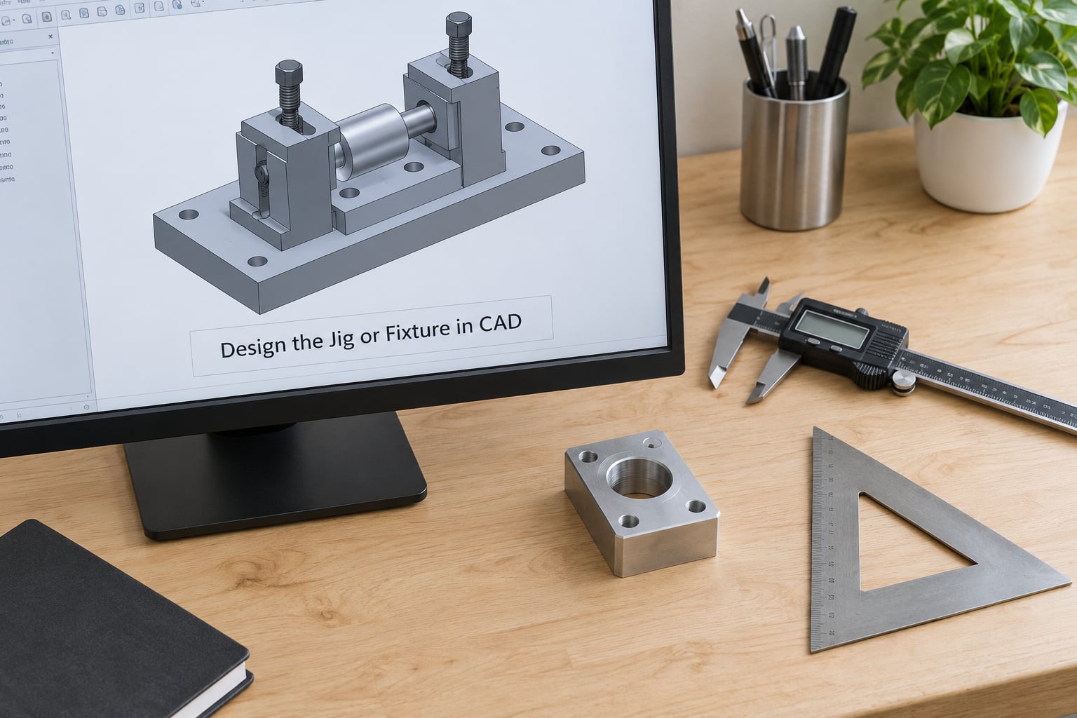
Build the jig around a base plate the workpiece nests into, then add features only where the task needs them. Simple geometry prints accurately and finishes quickly. Curved, cantilevered and thin-wall shapes are where dimensional drift shows up.
- Locators: short ribs or posts, not long rails. Three short points hold better and are easier to keep in tolerance.
- Stops: positive faces that set position, sized to the measured part plus clearance.
- Supports: a cradle rather than a flat pad if the part has mass, so it cannot rock.
- Handles: raised loops or a flange, so users do not grip the locating surfaces.
- Guide holes: at least 12 mm thick around the hole and 2 mm wider than the drill bit for clearance cutting.
- Replaceable wear strips: a slot for a sacrificial piece of plastic or a bushing where the tool rubs.
- Labels: embossed text like R1 or 5mm HOLE so the right face is obvious on the bench.
Cut tolerance holes at roughly 0.4 to 0.6 mm larger than the nominal size for FDM, and more for a drill bushing so the bit clears easily. Model clearance holes, not press fits, and remember that printed holes come out small and outside dimensions come out large, so the compensation runs opposite for each.
Leave room for fingers. A holder you cannot load one-handed gets worked around within a week, and a workaround means the jig is no longer repeatable.
4. Select the Material and Print Settings

Pick the material by temperature, load and what it touches. Nothing else matters nearly as much.
- PLA: stiff and easy to print, fine for templates and light locating tasks. It softens near a heat lamp or a sunny bench.
- PETG: the default for general shop jigs. Tough, dimensionally stable, and it creeps less than PLA under a steady clamp.
- ASA or ABS: for warm or outdoor use. ASA holds colour and weathers better; both need an enclosure to limit warping.
- Nylon: strong, wear resistant and tolerant of moisture, but it soaks up water and prints fussy. Good for bushings and high-use wear parts.
- Carbon or glass filled PETG: much stiffer than plain filament with less creep, and it machines cleanly after printing.
- TPU: for soft, non-marring contact surfaces, protective wraps and grip pads.
- Filled or resin: filled filaments give a machined feel and low friction. Resin gives fine detail and surface quality for inspection fixtures, with more handling.
Material choice then drives the settings. Printed layers bond weakly in tension, so orient the part so that load runs along the layers rather than peeling them apart. A clamp that squeezes across a layer line will crack; the same clamp loaded in the plane of the layers holds.
Use three or four perimeter walls and 30 to 50 percent infill for structural parts. Solid infill adds weight and print time without much gain once the walls are doing the work. Keep infill low only for handheld jigs, where lightness matters more than stiffness.
5. Slice and Print for Accuracy
Before printing any precision work, print a calibration coupon: a block 20 mm square and 50 mm tall, with a hole pattern, and measure it. Your printer’s error is consistent, so you can correct for it in the slicer.
Typical results on a well-maintained FDM machine are holes about 0.15 mm smaller and outside dimensions about 0.25 mm larger than modelled, which matches what makers report on forums. Measure your own machine rather than trusting those numbers.
- Adjust the slicer’s horizontal and vertical expansion, or scale the model, until the coupon matches the calipers.
- Print at 0.15 to 0.20 mm layers with three or four perimeters for accuracy parts.
- Set the first layer slow, ensure the bed is level and clean, and use a brim on large or tall prints.
- Avoid supports where you can. Design a 45 degree self-supporting surface instead.
- Add clearance around the first layer so the bed sheet does not pull the part out of shape.
- Keep the enclosure closed for ASA, ABS and nylon to cut warping.
If a dimension still drifts, the fix is usually walls and orientation, not slicer trickery. Thicker perimeters shrink error more than any profile change.
6. Finish, Assemble, and Test the Printed Jig
Remove supports while the part is still slightly warm, then break supports off with pliers rather than a knife. Break the remaining nubs flush and run a file or 400 grit paper along any surface that touches the workpiece.
Assemble the hardware, then test with the real part. Push it in by hand and check three things: it goes in the same way every time, it does not rock, and the tool or fastener lines up with the target without forcing.
Mark the part lightly with a scribe or permanent pen, measure, and change one variable at a time. Add a shim, widen a clearance by 0.3 mm, or shift a stop before you reprint the whole jig.
Hold the jig in normal use, not just on the bench. If it needs two hands to load or twists under clamp force, add ribs, another locating point or a metal core. Ten minutes of use testing saves a reprint.
Clean contact surfaces with isopropyl alcohol before you put a finished or plated part into the jig. Grit and plastic dust are what cause scratches people blame on the fixture.
7. Document and Improve the Fixture
Save the CAD file with a clear name such as bracket-drill-jig-R1, and put the slicer profile, material, layer height and orientation in a short note next to it. Record the measured part dimensions and the revision number, plus a photo of the finished jig with the real part in it.
That record is what makes the jig repeatable instead of a one-off. When the part changes to revision 2, you open the file and move the hole pattern rather than starting over. When the jig breaks, you reprint the same thing without hunting through old slicer settings.
Keep a small library of proven settings so new jigs reuse a profile you already trust. Add feedback notes after each use, especially where the tool rubs or where the part was hard to load.
Common Mistakes When 3D Printing Jigs and Fixtures
Measuring the drawing instead of the part. Take every dimension from the workpiece. Drawings do not include the tolerance stack of real parts.
Locators that are too long or too few. Long rails amplify error. Use three or four short touchpoints and nothing more.
Tight clearances. Printed holes shrink and outer walls grow. Cut clearance and widen it by 0.4 to 0.6 mm.
Bad orientation. If the load pulls layers apart, rotate the part so the load runs in-plane, or add a shell in the direction of stress.
Warping and layer splitting. Close the enclosure for ASA, ABS and nylon, slow the first layer, and add a brim. Poor bed adhesion usually looks like warping.
The wrong material. PLA creeps and softens under heat. Nylon wears well but absorbs moisture. PETG is the safe middle for most shop work.
Too much weight. A heavy handheld jig causes fatigue. Use lower infill and fewer walls on parts that never see load.
Marring finished surfaces. Print a TPU contact pad, deburr every edge, or coat the contact face with a thin matte varnish.
Skipping the test fit. Print one cheap version before committing to a full infill print. A thin-wall prototype takes an hour and answers the fit question.
A habit worth building early is leaving a little adjustment in every jig. Slots, T-track mounts, holes on a grid and shim pockets let the same printed part absorb variation between parts and between materials. Makers in shop forums consistently prefer adjustable jigs over fixed precision, because variation is always larger than the print tolerance.
Frequently Asked Questions
What is the best material for 3D print jigs?
For most shop jigs, PETG is the best starting point because it is stiff, easy to print and creeps far less than PLA under a steady clamp. Carbon or glass filled PETG adds stiffness for clamping work. Choose nylon or ASA where heat and wear matter, TPU for soft non-marring surfaces, and a filled filament when you want a machined surface finish that resists wear.
How do you get accurate fits from a 3D printed jig?
Print a calibration coupon, measure it with calipers, then compensate in the slicer. FDM machines typically run about 0.25 mm oversize on outside dimensions and 0.15 mm undersize on holes, so cut clearance holes larger and leave clearance on outer faces. Three or four perimeter walls shrink the error more than any profile change.
Are 3D printed jigs strong enough for shop use?
Yes, when load runs along layer lines and the walls are thick enough. A PETG jig with four perimeters and 40 percent infill handles clamping and assembly work well. For impact, high clamping force or continuous heat, reinforce the load path with steel shoulder bolts, a metal base plate or brass bushings. Test the jig in real use before trusting it.
Can you 3D print fixtures for welding or other high-heat work?
Use ASA, nylon or a high-temperature filled filament and keep the printed body away from direct flame and spatter. A printed carrier with steel locating pins or a graphite plate is a common approach, since the metal takes the heat and the printed part handles geometry. Never position plastic where it can contact molten metal or a hot workpiece directly.
What should I print first?
A drill guide or a simple template is the best first project because it is quick, forgiving of dimensional error and immediately useful. A clamp or a square for squaring parts works too. Keep the first design simple with flat surfaces and straight holes, print at low infill to save filament and print time, and only then move to fixtures.
When is 3D printing the wrong way to build a jig?
Print when the geometry is complex, the volume is low, and changes are likely. Machine it instead when you need full-size aluminium strength at high temperatures, a surface that cannot mark a finished part, or hundreds of identical tools. Carbon filled filament narrows the gap, and machined aluminium remains the benchmark machinists compare against.
That loop is really the whole of how to use 3D printing for jigs and fixtures. Start by picking one operation that frustrates you, then measure the real part and print a thin-wall prototype of the simplest holder that solves it. Measure, test fit, adjust one dimension at a time, and save the file with its settings. It takes an afternoon, and every jig you print afterwards starts from a known-good process instead of guesswork.