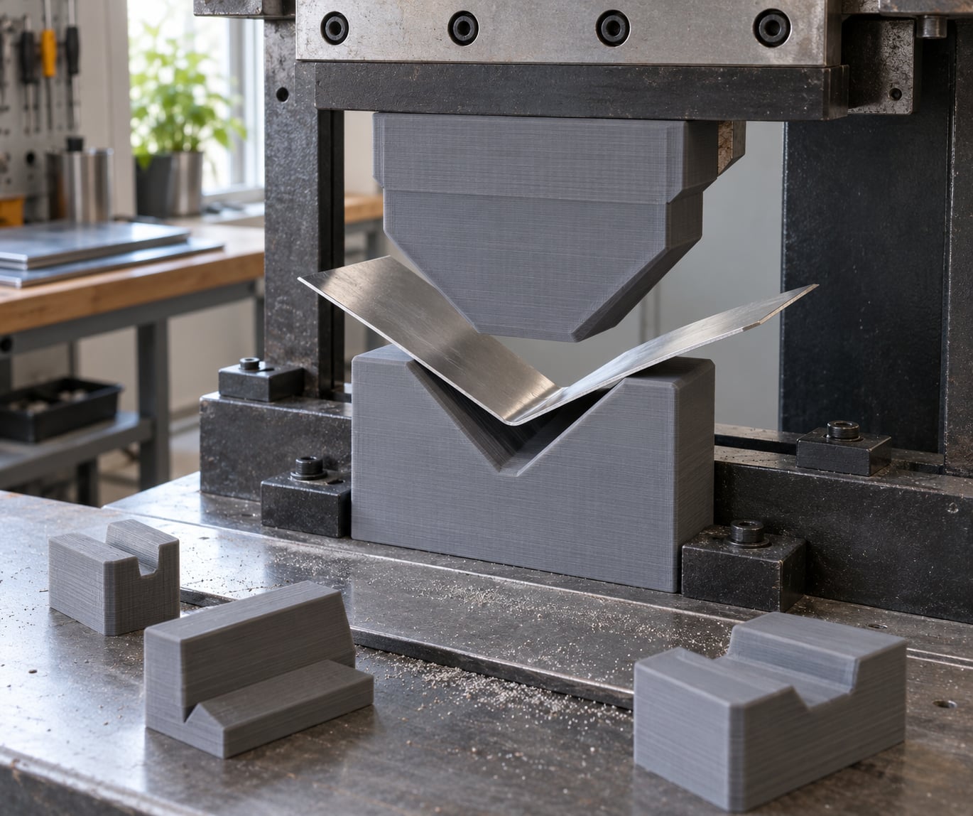
3D printed tooling for sheet metal forming means using additively manufactured punches, dies, formers, jigs and fixtures to bend, flange, hem, roll or otherwise shape metal, instead of machined or cast steel tooling. It makes sense when the run is short, the geometry is unusual, or a machine shop quote takes longer than the project itself.
The honest version is narrower than the marketing suggests. Printed polymer tooling handles prototypes, one-offs and low-volume jobs beautifully, then loses to steel once you need cycle life, surface quality or a high tonnage. This guide covers where the boundary sits, how to design a tool that stays inside it, and how to tell in advance which side of the line your job falls on.
Table of Contents
- 1What Is 3D Printed Tooling for Sheet Metal Forming?
- 2Why Use 3D Printed Tooling Instead of Conventional Tools?
- 3Which 3D Printing Processes and Materials Work Best?
- 4How to Design 3D Printed Tooling for Sheet Metal
- 5Define the sheet, the operation and the gauge
- 6Set clearance and radii deliberately
- 7Add draft and locating features
- 8Orient the print for the load path
- 9Plan for inserts and wear
- 10Punches, Dies, Blanks and Hold-Downs
- 11How to Account for Clearance, Bend Radius and Springback
- 12How to Print, Finish and Assemble the Tool
- 13How to Test and Validate 3D Printed Tooling
- 14Where 3D Printed Tooling Is and Is Not Suitable
- 15Frequently Asked Questions
- 16What material is best for 3D printed tooling for sheet metal forming?
- 17Can FDM printers make usable sheet metal forming dies?
- 18How strong does a 3D printed forming punch need to be?
- 19Do 3D printed sheet metal tools need machining?
- 20How do I choose the clearance for a printed forming die?
- 21When is conventional metal tooling better than additive tooling?
- 22Conclusion
What Is 3D Printed Tooling for Sheet Metal Forming?
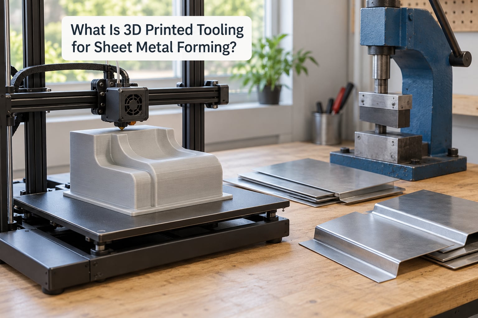
Sheet metal forming is the reshaping of sheet by plastic deformation. Nothing is cut away. The sheet is bent, flanged, hemmed, rolled, drawn or swaged, and the material yields permanently into the shape you want.
3D printed tooling is the set of tools that does that reshaping. Common pieces include male and female punches, forming dies and die shoes, blank holders, hold-downs, stripping plates, locating pins, support blocks, tube formers and inspection gauges. Fixtures and welding jigs sit alongside them as adjacent tooling, often built from the same job.
Two things make printed tooling different from a steel tool bought off the shelf. First, the geometry is not limited by what is economical to machine or grind, so unusual radii, undercut features and integrated locators become simple. Second, a change costs another print rather than another setup.
The important distinction is between prototype tooling and production tooling. Prototype tooling forms a handful of blanks so a design can be proven. Production tooling runs thousands of cycles under full press tonnage. Printed polymer can hold up under repeated low-volume cycles, but it is not a drop-in replacement for hardened steel in a production die set.
Why Use 3D Printed Tooling Instead of Conventional Tools?
Conventional press brake tooling has a fixed first-off cost that has to be amortised across however many parts you run. On a low-volume job that cost never amortises, and the quote becomes the deciding factor even though the print itself is cheap.
Iteration speed is the second reason, and often the bigger one. When a bend radius is wrong, a steel die gets re-ground or re-made. A printed tool gets edited in CAD and reprinted overnight, which turns a design problem into an afternoon problem. That is the difference the additive process actually buys you, and it holds even when a supplier could have cut the tool from stock plate.
Custom geometry is the third. A tapered transition, an eccentric hole pattern or a compound contour is straightforward in a print and awkward to fixture on a machine that expects standard tooling. Consolidation is related: a printed part can hold the locator, the pusher and the gauge in one body, which removes assembly steps on the press floor.
A concrete example from a fabricator working this way is a custom alignment fixture that holds a one-off bracket at a fixed angle for welding. Instead of tapping, scribing and remeasuring the part on the bench, the fixture holds the same position every time. Setup drops from a hand-fiddled operation to a load-and-press one, and the fixture prints overnight rather than waiting on a machine queue.
Low weight matters more than people expect. A tool light enough for one person to carry between the printer, the bench and the press changes who can do the job in a small shop. Density is also why printed tooling suits end-of-arm tooling on smaller robots.
Which 3D Printing Processes and Materials Work Best?
Process choice sets the resolution of the die face, and die face resolution is what decides whether the sheet marks. A layer line that is too coarse leaves a visible ridge on the finished part, and on stainless that ridge becomes a stress riser where the metal cracks later.
| Process | Typical material | Surface | Best use in forming |
|---|---|---|---|
| SLA / DLP | Tough and rigid resins, e.g. 10K-class formulations | Fine detail, needs light finishing | Sheet metal dies, flat patterns, prototype punch and die sets |
| SLS | Nylon, nylon composites | Grainy, good in compression | Hollow formers, tube swaging and rolling tooling where impact matters |
| FDM | ABS, ASA, PC, PA, carbon or glass filled nylon | Layer lines visible | Cheap hold-downs, jigs, fixtures, sacrificial formers |
| Polymer SLS | PEI-class high-temperature polymers | Strong, heat tolerant, lower elongation | Higher tonnage bends, stainless work, harder wearing faces |
| Composite tooling (fiber-filled) | Continuous or chopped fiber composite with resin | Matte, tough shell | Tools reinforced with embedded metal inserts |
| Metal AM | Steel or aluminium via powder bed or binder jet | As-machined, near steel behaviour | When the tool itself must be strong, hot or long-lived |
A few material properties decide more than the tensile number on the datasheet. Impact resistance tells you whether the punch nose survives a misload. Heat resistance matters if the sheet is warm or the tool runs near a hot forming process. Moisture sensitivity decides whether the tool drifts in dimension across a humid season, which is common in unfilled nylon. Creep behaviour matters most of all, because a bending load that is steady over minutes is exactly the load that flattens a polymer over time.
On the question of steel specifically: you cannot print sheet metal itself with an FDM or resin printer. Metal additive manufacturing is a separate set of processes using steel or aluminium powder, and some composite printers reinforce a printed body with a continuous metal matrix. Most forming tools do not need printed steel, but they often need printed steel in one place.
How to Design 3D Printed Tooling for Sheet Metal
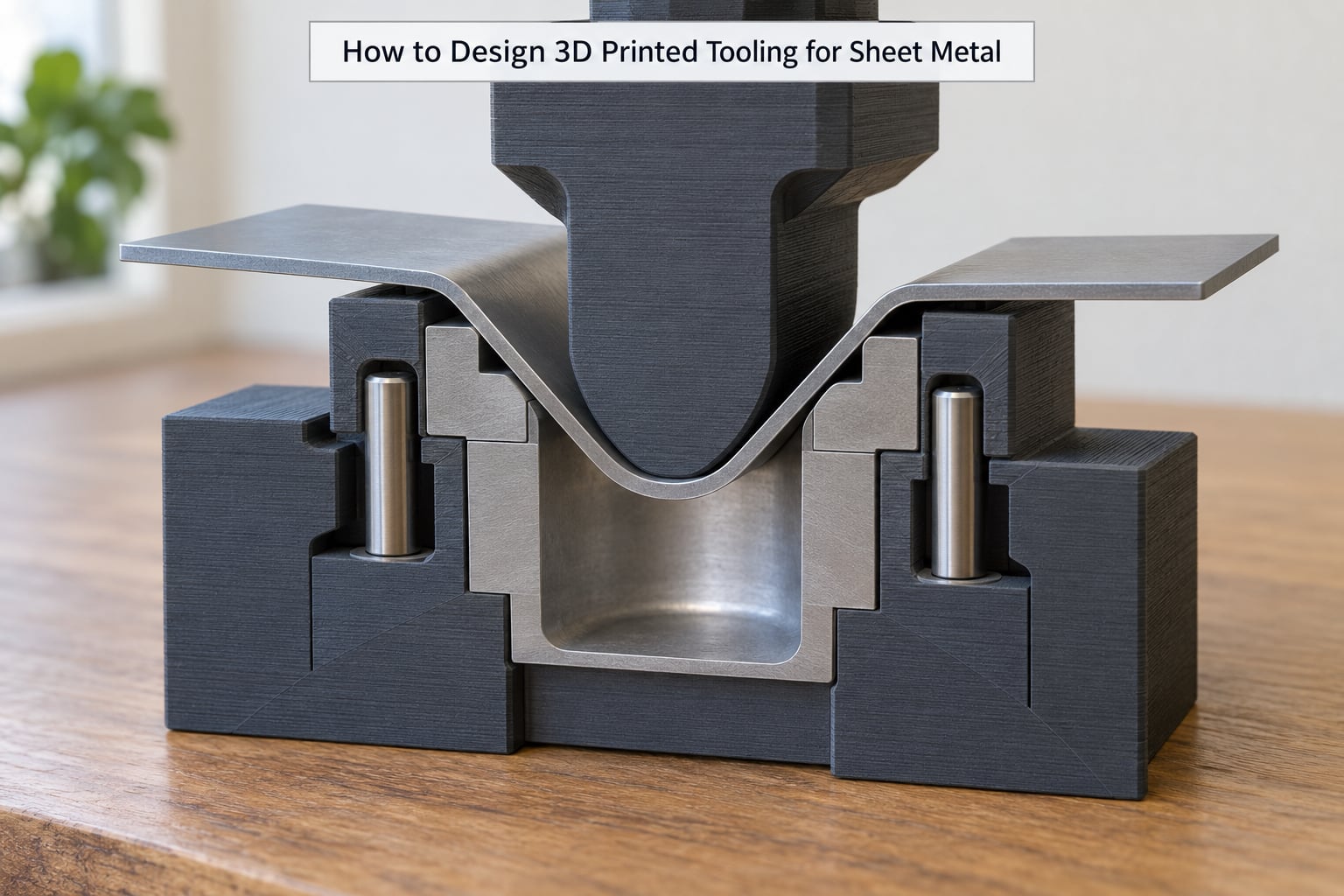
Design in the order that saves rework. Get the forming operation and the sheet defined first, because everything downstream depends on those two answers.
Define the sheet, the operation and the gauge
Record the material and its thickness, the bend angle, the flange length, whether the bend is up or down, the required inside radius, and how tight the angle tolerance has to be. Stainless forming at the same gauge as aluminium is a different job, because the springback is larger and the tooling must be sharper to avoid cracking the fold.
Set clearance and radii deliberately
Leave enough room between the punch and the die walls for the sheet to enter without binding. Too little and the tool gouges or cracks the material; too much and the sheet stops short of the angle you designed. The same care goes into the punch nose radius, which sets the inside radius on the finished part.
Add draft and locating features
A drafted wall lets the tool release from the formed part instead of tearing it off. Locating pins, shoulders or a pocket cut into the sheet give the tool something positive to register against, which is worth more than any increase in print infill. Put the locators where the operator can see and clean them.
Orient the print for the load path
Print so that the load runs along the layers rather than across them. Z-direction strength is the weak axis on every process in the table above, and a forming load is rarely vertical. A bend that loads the tool across the layers is the most common reason printed tools split at the radius. Orient the part so the bend axis lies in the build plate plane, and if the geometry prevents that, thicken the section.
Plan for inserts and wear
Leave pockets for hardened steel where the tool takes impact, abrasion or the highest forming force. Keep sacrificial contact faces separate from the structural body so the cheap part wears out and gets reprinted. If the tool mounts to the press with bolts, model and tap the holes in CAD, then drill and tap after printing rather than trying to print threads.
Punches, Dies, Blanks and Hold-Downs
The vocabulary is worth getting straight, because it maps directly onto what you model and what you print.
The punch is the moving member. A male punch pushes into the die to form a raised feature; a female punch is a shaped protrusion that presses the sheet from above onto the die shoulder. Most printed tooling is a punch, because the punch carries the shaped surface you actually designed.
The die is the fixed member that defines the inside geometry. The vee, or die opening, is the slot the sheet bends around. The die shoulder is the flat area outside the vee, and the die face is the working surface that the sheet wraps onto. The die face is where surface finish transfers to the part, which is why it gets the most attention in finishing.
A blank holder is the frame that clamps the sheet around the die so it cannot slide as it forms. Hold-downs, sometimes called pressure pads, do the same job in smaller fixtures and on lighter gauge material. A stripping plate pushes the formed part off the punch on the return stroke, and support blocks carry the punch body so the ram sees load through solid material instead of through a printed cantilever.
Where the load is highest, printed geometry needs support. The nose of a punch, the root of a vee and the heel of a flanged part see concentrated load, and these are exactly the corners that crack first. Add solid ribs behind the contact surface, keep the section thick through the nose, and never rely on infill alone where the load enters the tool.
How to Account for Clearance, Bend Radius and Springback
Clearance, bend radius and springback together decide whether the finished part matches the drawing. No single formula covers all of them, because the sheet material, thickness and grain direction change the outcome.
Bend allowance is the length of sheet consumed by the bend, based on the neutral axis shifting toward the inside of the fold as the material stretches outside and compresses inside. The k-factor expresses that neutral axis as a fraction of thickness, and its value depends on the material and the bend radius rather than being a universal constant.
Springback is the elastic recovery after the load comes off. The sheet wants to return toward flat, so a die must overbend slightly to hit the target angle. Heavier and stronger materials spring back more, and stainless steel springs back more than mild steel of the same gauge.
A simple illustrative case: 1 mm aluminium sheet, a 90 degree bend with a tight inside radius. Expect measurable springback, a visible die face radius on the outside of the fold, and a slightly longer developed length than a flat pattern assumes. The tool has to be opened up a touch, and the radius has to come from the punch nose rather than a sharp printed corner.
This is exactly why coupons exist. Cut two or three offcuts of the real material at the real gauge, form them with the printed tool, then measure the angle, the flange and the radius before you cut the first blank from real material. Adjust the die, reprint, and repeat until the coupon is right.
How to Print, Finish and Assemble the Tool
Printing a forming tool is mostly a stiffness exercise. Print with solid perimeters through the contact surface and a dense interior, orient the part for the load path, and do not fill the tool with sparse infill just to save filament on a part that is going to take a press load.
Warping is the most common printing defect and it ruins a tool before it ever reaches the machine. Keep the tool flat on the bed, add a brim on large footprints, keep the enclosure stable and warm, and avoid tall unsupported sections near the die face. A tool that prints flat and warps in the fixture will give inconsistent angles part to part.
Finish the die face. Deburr the vee, grind or polish the working surface, and check flatness with a straightedge on a granite surface plate. A high spot on the die face marks the sheet and shifts the bend line, so this is not cosmetic. Seal porous prints with epoxy or a filled coating before any sheet touches the tool, and let it cure fully.
Fit inserts next. Press or bond hardened steel into the pockets you modelled, keeping the working surface flush with the surrounding printed material. Mechanical retention is better than adhesive wherever you can get it. Centreline Engineering Solutions prints forming die tools for 14 gauge steel and embeds steel reinforcement by pausing a composite print mid-build, which is a neat trick for placing metal exactly where the load is.
Finally, make the tool removable. Drill and tap mounting holes rather than printing threads, add a handle or lifting eye, and confirm the tool clears the ram, the backgauge and the sheet on the return stroke before you plan a production run.
How to Test and Validate 3D Printed Tooling
Validation takes an afternoon and saves the batch. Work through it in order.
- Inspect the tool. Check the vee for print artefacts, confirm the die face is flat, and verify every fastener and insert is seated.
- Cut coupons from the same material and gauge as the real job.
- Set the bend angle as though the tool were solid, then start with a lower tonnage or air bend setting and increase gradually.
- Measure the bend angle, the flange length and the inside radius. Check the die face for scoring or marking.
- Adjust one variable at a time. An angle change is a die geometry change; a surface mark is a finish problem. Fixing both at once makes it impossible to tell what worked.
Watch specifically for a tool that opens up on the way down instead of holding its shape through the bend. When a printed die deforms under load, the part comes out long in the flange and the angle drifts low. That symptom points at stiffness and print orientation, not at the material choice, and it is fixed with thicker sections, added ribs or a steel insert.
Mark the tool with the material, gauge and settings you validated with, and keep the print settings with the file. Printed tools drift as parts wear, so a record of what worked lets you reprint the same thing rather than re-solving it.
Decide in advance when to upgrade. If the tool is holding up but the bend angle is drifting part to part, that is wear and it is time for a steel insert or a metal tool. If it failed suddenly without deforming first, that changes the conversation, and the next section explains why.
Where 3D Printed Tooling Is and Is Not Suitable
Printed tooling is a good fit for prototypes and design validation, low-volume production where the run is measured in tens rather than thousands, one-off parts and unusual geometries, and fixtures that hold a part for welding, assembly or inspection. Sheet metal repair and restoration work, where a panel exists for one car and will never repeat, is a natural application.
It also fits jobs where the forming force is modest. A small brake forming 1 mm or 2 mm sheet in aluminium or mild steel is within reach of a well-designed printed die. PolyForge publishes repeated demonstrations of a printed die bending stainless in a press brake, and makers on r/sheetmetalfab print tooling for stainless and aluminium parts as one-off jobs, so the stainless case is proven rather than theoretical.
It is not a fit for high tonnage forming of heavy or very strong material, high-volume production where cycle life dominates, severe abrasive contact, hot forming above the polymer’s softening point, or anything safety critical where a sudden failure could damage the part or hurt someone.
The failure mode deserves a straight mention. Engineers on eng-tips who have worked with ULTEM 9085 printed tooling describe the problem plainly: these tools do not fail ductile, so they get a bit explody when they fail. High-strength printed polymers resist a lot of load, then let go suddenly instead of deforming as a warning. Treat that as a reason to guard the tool, inspect it, and keep it out of applications where a fragment is dangerous.
Beyond capacity, printed tooling has softer limits. Polymer creeps under sustained load, so a tool left loaded overnight may not come back to its original angle. Wear transfers material to the sheet and can mark it. Fine cosmetic finishes and tight angle tolerances over many parts are where steel wins, and for a straightforward bend in mild steel, a supplier’s standard punch and die set will usually be cheaper and last longer than anything you print.
Frequently Asked Questions
What material is best for 3D printed tooling for sheet metal forming?
For most press brake work, a tough resin or a fibre-filled composite with steel inserts is the best balance of die face detail and load capacity. Fibre-reinforced composite shells with embedded steel handle heavier gauges and repeated cycles better than unfilled resin. High-temperature PEI-class polymers suit stainless work where heat and toughness matter. Match the material to the gauge and the run, not to the printer you already own.
Can FDM printers make usable sheet metal forming dies?
Yes, for light-gauge work, and they are the cheapest route. FDM is fine for hold-downs, blank holders, jigs and sacrificial formers. For actual die faces that contact sheet metal, the layer lines will show on the part, so print a flat plate, sand or mill it back to a smooth surface, and consider a thin epoxy or epoxy-filled coating. Most shops that need cosmetic quality on the part move to resin for the contact surface.
How strong does a 3D printed forming punch need to be?
Strong enough to carry the full forming force through its thinnest section without deflecting, not strong enough to resist a deliberate overload. That distinction matters because stiff printed tools transfer the load rather than bending away from it, so the failure arrives suddenly. Add steel inserts in the nose and root, keep solid perimeters through the contact area, and print so the load runs along the layers. Verify on coupons at the real material and gauge.
Do 3D printed sheet metal tools need machining?
They rarely need full machining, but most need some finishing. Expect deburring of the vee, flatness checking of the die face, light grinding or sanding, and drilling and tapping for mounting hardware. Polish the working surface if the part has any cosmetic requirement, because whatever texture the die face carries ends up on the sheet. Pockets for steel inserts should be finish-machined so the insert sits flush and the tool stays flat.
How do I choose the clearance for a printed forming die?
Start from the published clearance tables for your material, thickness and bend radius, then treat them as a starting point rather than a final answer. Printed tools deflect slightly under load, so the effective clearance changes during the stroke and is usually tighter than the nominal number suggests. Overbend slightly to account for springback. The reliable method is still empirical: form coupons, measure the angle and the flange, adjust, and reprint.
When is conventional metal tooling better than additive tooling?
Metal tooling wins on cycle life, cosmetic surface quality, tolerance stability over long runs and heavy gauges. If you are forming thousands of parts to a tight angle tolerance, machining or grinding a steel punch and die set pays for itself quickly and never drifts. It also wins for hot forming, severe abrasion and safety-critical operations. Additive tooling is the better answer for prototypes, short runs, one-off geometries and any job where the steel lead time exceeds the project.
Conclusion
Start by writing down the forming operation: material, gauge, bend angle, flange length, inside radius and the tolerance you actually need. Then pick a process and material to match that gauge and the expected cycle count, print a deliberately conservative prototype, and validate it on scrap coupons before any real material is cut.
3D printed tooling for sheet metal forming is most valuable when customization, speed and a low first-off cost outweigh long-term wear resistance. Get those three things and the economics are hard to argue with. Ignore them and a standard steel punch and die set from a supplier will still be the smarter buy.