To inspect 3D printed parts for defects, work through four layers in order: what you can see under good light, what you can feel, what you can measure against the model, and what you can test under load. Start cheap and escalate only where the risk justifies it. A part can look finished and still be warped, weakly bonded, or a fraction of a millimetre out where a fit matters.
That last point is where most people get caught. The bracket looks fine on the bench, then the fastener does not go in, or the assembly is off by a degree, or the part snaps two weeks later in the place the layer lines were already hinting at. Inspecting 3D printed parts is mostly about separating normal process marks from things that will actually cause a failure.
Below is the workflow I use on my own bench and the one that lines up with how small-batch shops run first-article inspection. Most of it needs no specialised equipment. The expensive methods only matter when the part carries load, holds pressure, or goes into service where a crack would hurt someone.
Table of Contents
- 1What You Need
- 2Step-by-Step: How to Inspect 3D Printed Parts for Defects
- 31. Prepare the Part and Define the Acceptance Criteria
- 42. Perform a Visual Inspection
- 53. Check Dimensions and Fit
- 64. Test Surfaces and Functional Performance
- 75. Look for Hidden and Internal Defects
- 86. Record Results and Decide Disposition
- 9Common Mistakes
- 10Frequently Asked Questions
- 11What are the most common defects in 3D printed parts?
- 12How do I check the dimensional accuracy of a 3D print at home?
- 13What tolerance should I expect from an FDM printer?
- 14Can I detect internal voids or weak layer bonding without a CT scanner?
- 15How do I know if a defect is cosmetic or actually a problem?
- 16Conclusion
What You Need
The starting point is the print specification. You need the material type, the layer height, the print orientation, the infill and perimeter settings, and ideally the batch of filament or resin used. Without that, a defect is just an observation.
Next is the reference geometry. That is the CAD or STL file, the drawing with tolerances, or an approved sample part that everyone agrees is the standard. For one-off prints, a tolerance test coupon printed in the same orientation does more work than a spec sheet written months earlier.
Then the physical kit. Here is the short version of what each tool is actually for.
- Lighting. A bright, diffuse lamp for general scans and a small directional light or flashlight for raking light across surfaces. Raking light at a shallow angle turns flat surfaces into a relief map.
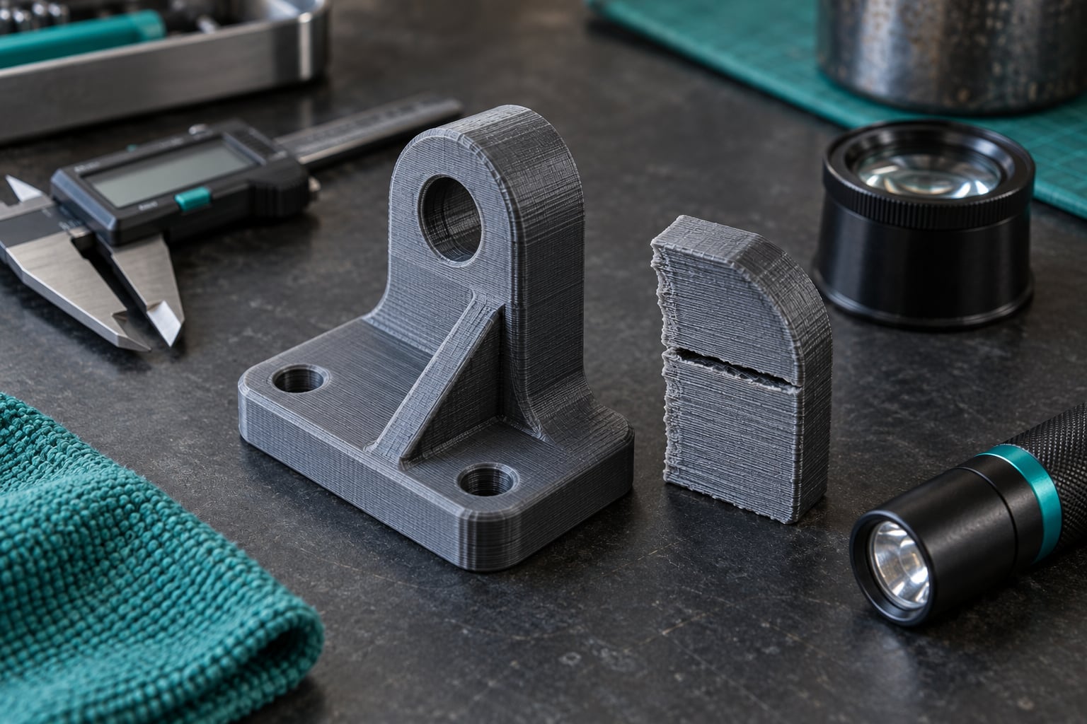
- Magnification. A 10x loupe or a phone macro lens. Layer adhesion problems that look fine from 40 cm disappear under magnification.
- Digital calipers. The workhorse. Roughly 150 mm jaw, reading to 0.01 mm. Good enough for most FDM checks.
- Micrometer. Needed when you are holding a tolerance below about 0.1 mm, particularly on resin prints and machined-in features.
- Feeler gauges, depth gauge, thread gauge, bore gauge. Small, cheap, and each solves one specific measurement you cannot do well with calipers.
- Surface plate or granite square. For flatness. A dial indicator on a flat reference surface tells you more than calipers ever will about a warped lid.
- Cleaning supplies. Isopropyl alcohol, a brush, lint-free wipes. You cannot judge a surface through the dust and skin oil of a fresh print.
- Tolerance coupons and a temperature probe. A thermometer near the part matters more than most people expect.
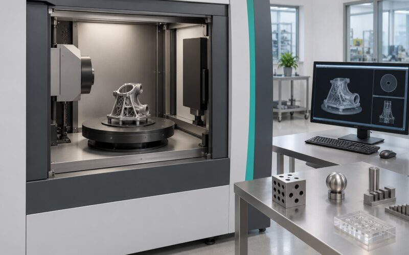
Beyond the bench kit sit the advanced instruments: an optical 3D scanner for full-surface comparison, a coordinate measuring machine for tight tolerances, and CT, X-ray or ultrasonic equipment for internal defects. Add those when the part is structural or the cost of a failure is high, not before.
The matching principle is simple. Match inspection depth to material, process and consequence. A decorative PLA figurine needs a visual pass. A resin casting pattern, a pressure fitting, or a metal powder part needs metrology. Match the method to the risk, and you will not overpay for a scanner or under-inspect a load-bearing component.
Step-by-Step: How to Inspect 3D Printed Parts for Defects
Six steps, in this order. Each one is cheaper and faster than the next, and each one narrows down what the next one needs to look at.
1. Prepare the Part and Define the Acceptance Criteria
Remove supports before you judge anything. Support scars, witness marks and the roughness where a support interface was cut are part of the part now. If a feature was broken during removal, note it before you start looking for other problems, otherwise you will forget which defect was original.
Clean the part. Wipe with isopropyl alcohol and let it fully dry. On resin prints, complete the wash and cure cycle first; solvents can mask surface defects and a tacky uncured surface will fool both your eye and your calipers.
Let the part reach room temperature before measuring. This one catches people constantly. A part that came off a heated bed can be tens of degrees warm, and thermoplastics like ABS and ASA grow measurably when hot. Measuring a warm part and comparing it to a cold CAD dimension guarantees a false non-conformance.
Now write the acceptance criteria before inspection, not after. Four classes matter:
- Dimensional. The dimensions that matter functionally, with a stated tolerance on each. An L-bracket’s hole spacing matters. The diameter of a decorative boss does not.
- Cosmetic. Which surfaces are visible to a customer, and how much layer texture is acceptable there.
- Mechanical. Any load, torque or cycle requirement, and how you will verify it.
- Internal quality. Whether porosity or lack of fusion matters in this application at all, and what evidence you will accept.
Having these written down is what turns a nervous look at a part into an inspection. Without criteria, everything is a judgement call and nobody can repeat your decision.
2. Perform a Visual Inspection
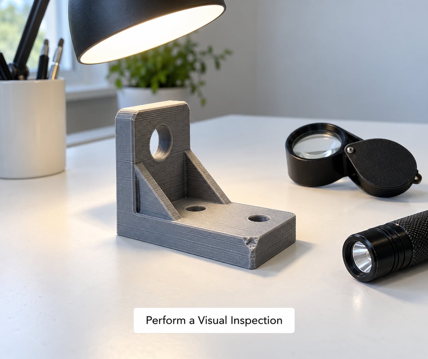
Start under bright, even light, then switch to raking light. Rotate the part continuously. Every part has at least one face you have never looked at properly, and it is usually where the defect is.
Here is what to look for, and what it usually means.
- Layer separation or delamination. A visible gap or a lifted edge between layers. Serious, and a bonding or temperature problem rather than a cosmetic one.
- Cross-section voids. Gaps inside walls and perimeters visible at a cut face or at a natural opening. These come from poor bridging, retracted moves, or infill that did not bond.
- Under-extrusion. Thin, stringy walls and gaps between perimeters, visible as light shining through a solid-looking wall.
- Over-extrusion. Blobs, thick seams and a generally smeared surface where material piled up.
- Warping. Corners lifted off the bed, a part that rocks on a flat surface, or a lid that no longer sits flat.
- Cracking. Especially around holes, tall walls and sharp corners. In FDM these usually trace back to layer adhesion and stress concentration.
- Elephant foot. A rounded, swollen bulge on the first few layers at the bed, which eats into fit at the bottom of a bore or a hole.
- Ringing and Z-banding. Repeating ripples on vertical faces and a repeating thickness change up the Z axis. Ringing is usually acceleration or belt tension. Z-banding is usually a feed problem.
- Stringing. Fine filaments between features, usually cosmetic unless they ended up inside a bore or a moving fit.
- Incomplete features. A missing boss, a hole that stopped early, a chamfer that never started. Often a slicing or small-feature failure, not an extrusion failure at all.
Magnify anything suspicious before you write it down. What looks like a scratch at arm’s length is frequently a fine crack at 10x, and the two get very different dispositions.
Then compare against the reference. Overlay the CAD model or view the part against an approved sample and ask whether the difference is within what the process can deliver. Step 2 works because it produces a list of specific observations. Step 3 turns those observations into decisions.
3. Check Dimensions and Fit
This is where most self-inspections quietly go wrong, because of technique rather than tolerance. Three errors account for most of it: parallax from reading the scale at an angle, measuring in the wrong place on the part, and measuring while the part is still warm.
The procedure that works:
- Measure at room temperature, after the part has sat for an hour or more.
- Take measurements in multiple locations where they matter. For a hole, measure at three depths: near the top, mid-depth, and near the bottom. A hole that is correct at the top and 0.2 mm oversize at the bottom is a real problem, and a single reading would have missed it.
- Repeat each critical dimension at least twice, from slightly different positions. Consistent readings mean your technique is sound. Readings that move by more than the tool resolution mean you have a technique problem, not a part problem.
- Measure the mating feature, not just the feature. If it has to fit a standard fastener, measure the fastener and the hole together.
- Check hole position and squareness, not only diameter. On a bracket, an oblong or out-of-square hole pattern causes more failures than a slightly oversize bore.
- Compare against tolerance, not against zero. A reading that looks wrong can be inside tolerance. A reading that looks fine can be out.
Reference values help you know what is reasonable. These are the ranges experienced makers report, not guarantees:
| Feature or process | Typical achievable deviation | What usually limits it |
|---|---|---|
| Well-tuned FDM, external dimensions | Around plus or minus 0.2 to 0.3 mm | Calibration, extrusion consistency, thermal drift |
| Well-tuned FDM, small internal features | Around plus or minus 0.1 mm | Nozzle diameter and hole compensation |
| FDM holes and bores | Usually undersize, often by 0.1 to 0.3 mm | Contraction during extrusion, elephant foot |
| MSLA resin | Around plus or minus 0.1 to 0.2 mm | Suction, peel force, curing shrinkage |
| Thick parts in high-shrinkage materials | Worst-case deviation often appears along the longest axis | Volumetric shrinkage and thermal contraction |
Two rules of thumb are worth internalising. First, FDM holes almost always come out smaller than nominal, so a printed hole often needs drilling or reaming to hit a close fit. Second, reducing layer height improves Z accuracy and surface finish but does very little for XY accuracy on an FDM machine, which is limited by mechanical rigidity and calibration instead.
For flatness, put the part on a surface plate or a piece of known-flat glass with a granite square on it and slide a feeler gauge under the low point. For threads, a thread gauge tells you in a second whether you have a real thread or a decorative spiral that will strip.
Finally, separate functional, cosmetic and critical dimensions in your notes. Mixing them is how a part gets rejected for a 0.3 mm error on a feature that never touches anything.
4. Test Surfaces and Functional Performance
Surface and functional checks come before any destructive testing. The order matters: once you have bent a part to see whether it holds, you have destroyed the evidence for everything downstream.
On surfaces, compare texture against the approved sample rather than against an idea of smooth. For coated or painted parts, look for runs, sags, missed areas and pinholes. On resin prints, check the surface for a skin that looks dull and slightly soft, which points to under-cure rather than to flow or geometry.
Then run the non-destructive functional checks:
- Thread and fastener test. Screw a fastener in by hand. If it needs a wrench, something is wrong. It may be interference from elephant foot, an uncompensated hole, or a print orientation that left the walls uneven.
- Fit test against a real mating part. This catches more failures than any other check, and it takes seconds.
- Leak test for fluid-handling parts: soapy water and a pressure hold. Start well below any pressure rating and increase cautiously.
- Rigidity check. Apply a light, controlled load and watch for flex, clicking or a change in shape. Plastic parts can feel fine and still be weak.
- Flex or snap test on a sacrificial coupon, not on the part you are signing off. It is the only bench method that tells you about interlayer bond strength.
Listen as well as look. A click under load is a joint separating or a layer beginning to peel, and it is audible well before it is visible.
Only when everything above passes should you apply real stress to the actual part, and then only to a defined limit, with a defined failure mode in mind. A part with no defined load case cannot be meaningfully tested.
5. Look for Hidden and Internal Defects
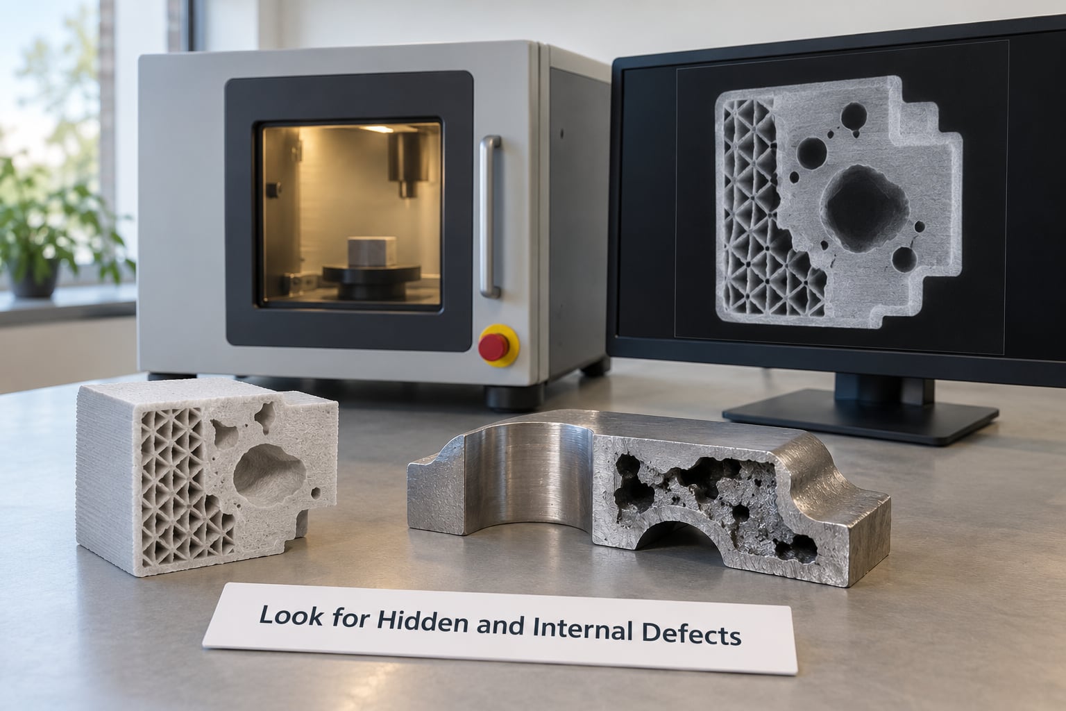
Visual inspection cannot see inside. It never could, and pretending otherwise is the most common gap in a hobbyist inspection routine. The question is not whether to use internal testing, but when it is worth the cost.
Escalate to non-destructive testing when any of these apply: the part is loaded in tension or bending in service, it holds pressure, it is a medical or food-contact application, it is metal or a fibre-reinforced filament, it goes into production as a supplier part, or the visual and dimensional results are ambiguous in a way that matters.
What each method does and does not find:
| Method | Finds | Misses or limits |
|---|---|---|
| Dye penetrant testing | Cracks open to the surface, in non-porous materials | Nothing internal; needs a clean surface; not for porous or rough-surface materials |
| Ultrasonic testing | Internal voids, delamination, lack of fusion; gives depth information | Needs a skilled operator and couplant; geometry limits access |
| X-ray radiography | Voids, inclusions, porosity, wire and some geometry; a 2D projection | Overlapping features hide each other; density differences must be adequate |
| CT scanning | Full 3D map of internal voids, delamination, trapped powder, incomplete geometry | Costly; part size is limited; some polymers are hard to penetrate |
| Optical 3D scanning | Complete external surface deviation against the CAD model | Surface only, by definition |
| Weight or displacement check | Gross porosity and missing material across a whole part | No location information; crude but genuinely useful as a screen |
For makers without a lab, there are real intermediate options. A sectioned sample cut from the same plate, at the same orientation, tells you a great deal about wall quality and void frequency. Counting voids per unit area across several sections gives you a repeatable figure. So does weighing the part against a solid model of the same volume computed from the CAD file.
A destructive coupon from the same plate, flexed to failure, gives you a comparative interlayer bond number. Print it in the same orientation as the real part, because bond strength is directional. Three coupons beat one every time.
For resin prints, internal defects come from insufficient cure, trapped bubbles, or voids left by suction. Washing and curing problems show up as a dull or tacky surface, which is a strong enough indicator on its own.
Step 5 answers the question forum users ask most: yes, you can learn a lot without a CT scanner, but only with sectioning and coupons, and those tell you about the process rather than about this specific part. That distinction matters when you are qualifying a part for service.
6. Record Results and Decide Disposition
An inspection you did not write down did not happen, and this is where traceability starts. Record at minimum: part identifier and print batch, printer and material lot, the full settings snapshot, inspector name and date, measured values with the tool used, photographs of anything you flagged, test results, and the disposition.
Photographs need a scale reference in frame. A crack photographed without a ruler or caliper in shot cannot be measured later, and cannot be compared against the next one from the batch.
Then assign a disposition from four options, and be strict about which ones you are allowed to use.
| Disposition | Use when | Requirement |
|---|---|---|
| Pass | All criteria met | Record the measurements |
| Rework | Defect is correctable and the correction is defined: re-drill, sand, fill and reprint a feature, reprint the part | Verify after rework and record what changed |
| Use-as-is | Deviation is real but harmless for this application, such as a visible layer line on a non-critical face | Requires a written justification and, in most workflows, approval from someone other than the inspector |
| Reject | Defect affects function, strength or safety | File a non-conformance record, quarantine the part, and feed the cause back into settings or material |
The distinction between use-as-is and reject is where quality systems are won or lost. A cosmetic defect in a cosmetic application is not a defect. A cosmetic defect on a sealing face is. Decide it before the part is in your hand if you can, because afterwards it is much harder to argue.
Common Mistakes
These are the errors I see most often, including in my own early work.
Inspecting only one side. A part that passes a visual check from above can have a torn support interface on the underside. Rotate through at least 360 degrees under the same light, and if the part has an underside, give it its own pass.
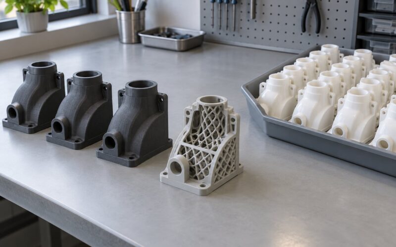
Judging quality from appearance alone. A glossy, even-looking FDM part can have poor interlayer bonding and 8% voids inside. The reverse is also true: a visibly rough functional bracket can be entirely sound. Appearance is a screen, not a verdict.
Measuring the wrong features. People measure what is easy to reach instead of what carries the load. List the functionally significant dimensions before you pick up a caliper, and measure only those plus anything you need for the acceptance record.
Using damaged or unsuitable tools. Calipers dropped on a hard floor go out of parallel and will happily read wrong for years. Check zero closure on a clean flat surface before you start, and keep a micrometer for anything tighter than 0.1 mm.
Skipping the batch record. One bad part is an event. Three bad parts from one filament roll is a material problem, and you cannot tell the difference without the batch number attached to each part.
Confusing normal process marks with defects. Layer lines, a visible seam, slight elephant foot, and minor ringing on a vertical face are all expected output from a working machine. Calling them defects either means you are calibrating to an impossible standard or you are missing the real problem behind the noise.
Applying destructive tests too early. Snapping the part to see whether it is strong destroys the flatness and dimensional evidence you have not taken yet. Test a coupon, or record everything before you break anything.
Measuring a warm part. Covered above, and worth repeating because it produces confident, repeatable, wrong readings, which is the worst combination.
A few practices fix most of this. Build a sampling plan rather than inspecting everything identically, so you inspect every part on the critical features and sample the rest. Train inspectors against a set of samples with known verdicts, since two people looking at the same bracket should reach the same conclusion. And escalate anything ambiguous instead of guessing, because the cost of an unnecessary second opinion is far below the cost of a wrong call.
Frequently Asked Questions
What are the most common defects in 3D printed parts?
The most common defects fall into four groups. Dimensional problems, especially undersize holes, out-of-square hole patterns and warped parts, show up most often in functional FDM parts. Surface defects include stringing, ringing, Z-banding, blobs and support scars. Internal defects are voids, porosity and delamination between layers, which are invisible without sectioning or a scan. Process defects cover first-layer adhesion failure, bridging failures and incomplete features from slicing. Cosmetic texture like visible layer lines is normal output, not a defect, and should not be logged as one.
How do I check the dimensional accuracy of a 3D print at home?
Use digital calipers reading to 0.01 mm for most checks. Print a tolerance test coupon in the same orientation as the real part, let both cool to room temperature for at least an hour, then measure each feature with the calipers parallel to the surface and viewed straight on to avoid parallax. Measure holes at three depths and repeat critical dimensions twice. Compare each reading against the tolerance in your drawing rather than against zero, and use a micrometer only when your tolerance sits below 0.1 mm.
What tolerance should I expect from an FDM printer?
For a well-tuned machine, external dimensions usually land within about plus or minus 0.2 to 0.3 mm, and small internal features within about plus or minus 0.1 mm. Holes and bores generally print undersize by 0.1 to 0.3 mm, so design mating holes with that in mind or drill them afterwards. These figures are widely reported by makers but depend entirely on your calibration and material, so run a tolerance coupon rather than trusting a number from a forum. Reducing layer height improves Z accuracy but barely changes XY accuracy.
Can I detect internal voids or weak layer bonding without a CT scanner?
Yes, partially. Print three sacrificial coupons from the same plate in the same orientation as the real part, then flex each to failure and record the peak load. That gives a repeatable interlayer bond figure for your process. Section a second coupon and count voids per unit area to measure porosity. Compute the expected volume from the CAD file and weigh the part against it to catch gross missing material. What you cannot do this way is confirm that one specific part in your hand is free of internal defects, which is exactly what CT or ultrasonic testing is for.
How do I know if a defect is cosmetic or actually a problem?
Ask whether the defective feature carries load, holds pressure, seals, locates another part, or is visible to a customer. Layer lines, a faint seam or minor ringing on a non-critical face are cosmetic and should not be logged. The same features on a sealing face or a mating surface are functional, because they change how the part fits or leaks. Voids, cracks and delamination are structural wherever they appear, because interlayer bond strength is the weakest direction in a printed part. Write the rule down before you inspect so the call is not made per part.
Conclusion
If you take four actions from this, make them these. Write down the critical dimensions and their tolerances before you print. Give the part a full visual pass under bright angled light with rotation, at magnification. Measure those critical dimensions at room temperature with good calipers, at more than one point, and compare against tolerance rather than against the number you imagined. Only then decide whether deeper testing is justified by the consequence of failure.
Everything after that is refinement: tactile checks, coupons, scanning, formal records. Match the depth of your inspection to the material, the process and what happens if the part lets you down. A cosmetic enclosure does not need a CT scan. A pressure fitting, a load-bearing bracket or a metal part under certification does, and no amount of looking at it with a loupe will tell you what you need to know.