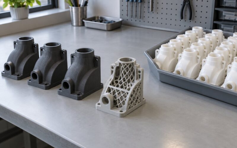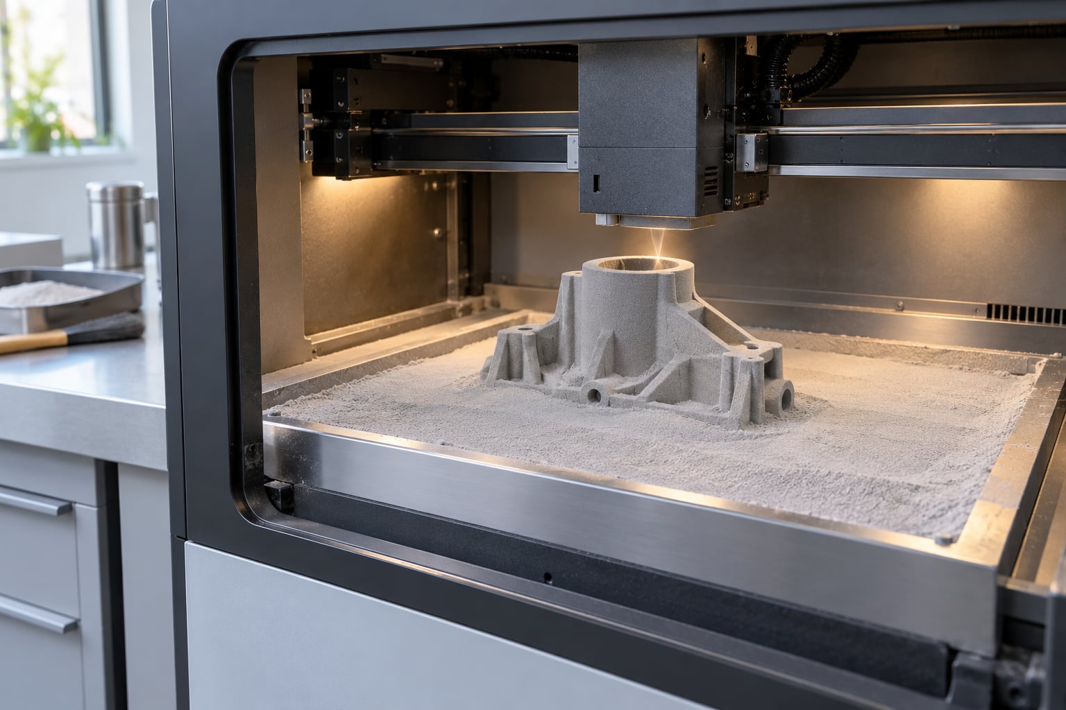
SLS 3D printing uses a high-powered CO2 laser to fuse polymer powder, usually nylon PA 12, layer by layer inside a heated chamber. The loose powder around the part supports it while it builds, so you get strong, complex geometry with no support structures at all.
That single detail is why SLS matters. FDM prints layer lines with weak spots between them, SLA prints beautifully but brittly and needs scaffolding, and SLS lands somewhere between: repeatable, tough, isotropic parts in small batches without a single mould or fixture.
The catch is that it is an industrial process, not a desk machine. Surface finish is matte and grainy, minimum wall thickness is real, and the economics only work when you batch parts or need genuine mechanical performance. This guide covers how the process works, what it makes, and where it beats the alternatives so you can tell before you spend anything.
Table of Contents
- 1What Is SLS 3D Printing and When Should You Use It?
- 2How Does Selective Laser Sintering Work?
- 3The seven-step SLS printing process
- 4What SLS is typically accurate to
- 5What Materials Can SLS 3D Printing Use?
- 6What Are the Main Advantages of SLS 3D Printing?
- 7What Are the Limitations of SLS 3D Printing?
- 8When to Use SLS 3D Printing
- 9Functional prototypes that get handled
- 10Jigs, fixtures and robotic end-of-arm tooling
- 11Snap fits, clips and living hinges
- 12Spare parts for legacy equipment
- 13Low-volume end-use production
- 14When SLS is the wrong tool
- 15SLS Compared With Other 3D Printing Processes
- 16SLS vs MJF: the modern sibling technology
- 17How to Choose an SLS Material for Your Part
- 18What Post-Processing Does an SLS Part Need?
- 19How to Prepare a Part for SLS 3D Printing
- 20Frequently Asked Questions
- 21Is SLS 3D printing suitable for functional parts?
- 22Do SLS 3D printers need support structures?
- 23What is the difference between SLS and SLA 3D printing?
- 24Can SLS parts be used for production?
- 25How accurate is SLS 3D printing?
- 26Can SLS parts be painted or dyed?
- 27Conclusion
What Is SLS 3D Printing and When Should You Use It?
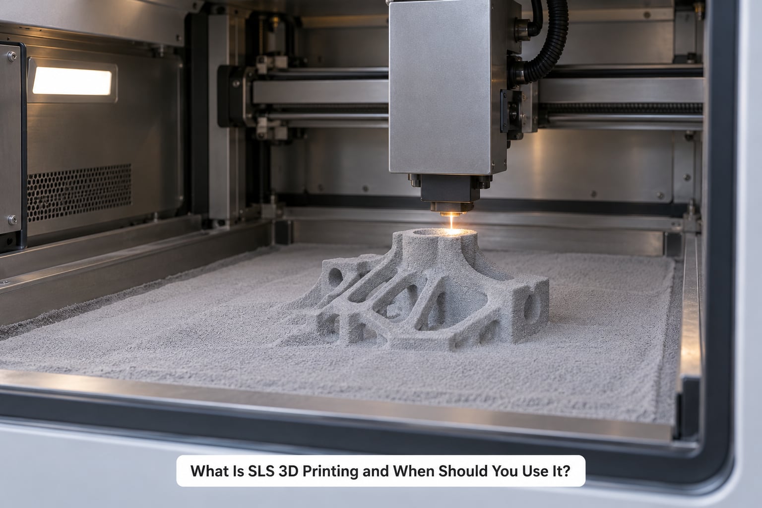
Selective laser sintering is a powder bed fusion process: a computer slices your CAD model into thin cross-sections, spreads a layer of polymer powder across a build platform, and a laser scans each cross-section, heating the particles just enough to fuse them. The untouched powder stays loose and becomes the support for the next layer, so overhangs, internal channels and interlocking features all come out of the machine in one piece.
Developed at the University of Texas at Austin in the late 1980s by C.R. Decherd, the process has grown from a rapid prototyping curiosity into the backbone of low-volume manufacturing. Practitioners on production forums like Hubs’ community forum consistently describe it as the professional workhorse: the one they stopped going back to FDM after using.
Here is the short version of when to use it.
- Functional prototypes that get handled, clamped and dropped, where a brittle FDM or SLA layer would fail.
- Jigs, fixtures and robotic end-of-arm tooling that need impact resistance and light weight.
- Complex geometry with internal channels, lattices or snap fits that would need support in any other polymer process.
- Spare parts for legacy equipment where the original mould has been scrapped and the demand is too small to justify recreating it.
- Short-run end-use production in the tens to low hundreds, batched and nested to make the per-part economics work.
- Housings, ducts and enclosures that need chemical and moisture resistance rather than a glossy finish.
And when not to use it: appearance-only concept models, parts needing tight machined tolerances down to a few hundredths of a millimetre, very large structures beyond a typical 330 x 330 x 600 mm build, and single cheap hobby prints where a home FDM machine does the job for less.
How Does Selective Laser Sintering Work?
The cycle runs the same way for every machine, from a small desktop unit to a full production cell. Understanding the sequence tells you why the tolerances behave the way they do.
The seven-step SLS printing process
- CAD preparation and slicing. Your solid model is oriented in the build volume, then sliced into layers, usually around 0.1 mm thick.
- Powder deposition. A recoater blade spreads a fresh, measured layer of powder across the bed.
- Laser sintering. The CO2 laser traces the cross-section, heating particles to just below their melting point so they fuse without flowing.
- Bed lowering. The platform drops by one layer height and the cycle repeats.
- Cooldown. Once the build finishes, the chamber cools slowly so the part relaxes without cracking.
- Unpacking. The part is lifted out and depowdered; loose unsintered powder is shaken and vacuumed away, and a good share goes back for reuse.
- Post-processing. Bead blasting, dyeing, infiltration or machining, depending on what the part has to do.
The chamber itself is the quiet hero. It sits just under the polymer’s melting point for the whole build, which is why laser energy only needs to sinter rather than melt, and why parts come out with fewer layer-direction weak points.
What SLS is typically accurate to
| Specification | Typical SLS figure | What it means for your part |
|---|---|---|
| Dimensional tolerance | Around +/-0.2 mm | Fine for slip fits and clearance holes; leave slack on press fits |
| Layer thickness | About 0.1 mm | Determines the staircase you can still see on curved surfaces |
| Minimum wall thickness | Roughly 0.8 to 1.0 mm | Thinner features print weak or not at all |
| Heat deflection temperature (PA 12) | Around 170 °C | Suitability depends entirely on your service temperature |
| Typical build volume | Around 330 x 330 x 600 mm on mid-size machines | Check the Z height, it is usually the limiting dimension |
| Surface finish as printed | Matte and grainy | Bead blasting smooths it; clear coats fill it further |
Holes deserve their own warning, and it is the one that catches people out. Heat pulls powder slightly as it fuses, so a nominal 10 mm hole often comes out closer to 9.7 mm and a shaft slightly undersize. Machine holes undersize in your CAD model and let the supplier confirm with a test build.
What Materials Can SLS 3D Printing Use?
PA 12 nylon is the default and the reason most people pick SLS over other polymers. It combines toughness, chemical resistance and dimensional stability at a price the process can absorb, and it is the powder every machine manufacturer supports first.
| Material | Key properties | Typical uses |
|---|---|---|
| PA 12 nylon | Tough, stiff, chemically resistant, stable | Functional prototypes, housings, jigs, ducting |
| PA 11 nylon | Slightly tougher and more flexible than PA 12 | Clips, snap fits, living hinges, handles |
| TPU | Rubber-like, very high elongation and abrasion resistance | Grippers, bumpers, protective parts |
| Polypropylene | Chemical and fatigue resistant, semi-flexible | Fluid handling, hinges, straps |
| Carbon-fibre-filled PA | Stiffer and stronger, lighter, higher heat resistance | Robotic grippers, structural brackets |
| Glass-filled PA | Stiffer, more dimensionally stable, lower shrinkage | Fixtures and plates needing rigidity |
Fillers change the machining story as much as the strength story. Unfilled nylon machines and finishes well; carbon-fibre-filled grades cut faster with abrasive tooling but eat conventional carbide blades, so flag that in your order if you plan to post-machine threads or bores.
What Are the Main Advantages of SLS 3D Printing?
The advantages all trace back to two facts: the powder supports the part, and the whole layer is heated evenly. Those two things produce a machine that behaves differently from every extrusion- or resin-based option.
- No support structures. Overhangs, bridges, internal channels and enclosed volumes print without scaffolding, and nothing has to be cut off afterwards.
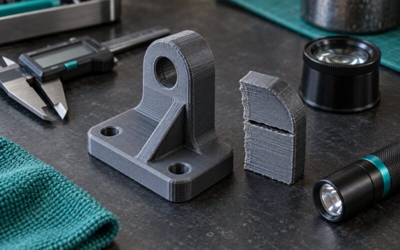
- Isotropic strength. Because the whole layer sits in a heated chamber, properties are nearly identical in every direction, unlike FDM where a layer bond is the weak line.
- Complex internal geometry. Lattice infill and hollow channels that would be impossible to support are simply printed as solid geometry.
- Batch nesting. Many small parts fit in one build, so the machine cost and operator time are shared across everything in the chamber.
- Repeatability. Once a machine and material are dialled in, part twenty matches part one, which is what makes short-run production viable.
- No tooling. There is no mould to design, machine or maintain, so a one-off part costs about the same to produce as a batch of one.
Add in toughness. Nylon absorbs impact and flexes before it snaps, so an SLS part that gets dropped onto a workshop floor usually survives the drop. That is exactly why grippers, brackets and handling aids are printed this way.
What Are the Limitations of SLS 3D Printing?
The limitations are real and worth stating plainly, because the gap between expectation and delivered part is the most common complaint in production forums. SLS parts arrive rough and porous-looking, which disappoints anyone expecting a finished consumer product.
- Surface finish. Matte and grainy as printed. Bead blasting helps, clear coat helps more, but you will never match SLA without significant finishing work.
- Porosity and water tightness. Sintered nylon absorbs moisture and is not watertight until it is infiltrated or coated.
- Minimum wall thickness. Below roughly 0.8 mm features are fragile or missing, so thin shells need to be ribbed or thickened.
- Limited colour and material choice. Parts come out white or grey unless dyed, and the range of available polymers is far narrower than FDM’s.
- Holes and threads shrink. Thermal shrinkage means non-critical features need a generous allowance or machining afterwards.
- Equipment and minimum economics. Machines are a serious capital investment, and single-part orders carry a setup burden that makes small jobs expensive.
- Build volume limits. A single part has to fit the chamber, so oversized structures mean assembly from several printed components.
There is also post-processing to budget for. Depowdering, blasting and inspection are not optional extras, and small fragile features have been known to break during unpacking, which is why practitioners print oversize sacrificial supports where the geometry allows.
When to Use SLS 3D Printing
Reach for SLS when the part has to survive handling, the geometry fights back against support structures, or the run is too small for a mould. The cases below are where it earns its cost.
Functional prototypes that get handled
Anything that gets assembled, clamped, dropped or repeatedly cycled belongs here. A housing that has to slide onto a rail, or a lever that gets pushed a hundred times a week, needs the isotropic strength and layer adhesion SLS gives you.
Jigs, fixtures and robotic end-of-arm tooling
Robot grippers want to be light, tough and slightly compliant. Carbon-fibre-filled PA gives a gripper strong enough to hold a part and light enough not to slow the arm, with a lattice interior that trims weight without a moulded pocket.
Snap fits, clips and living hinges
PA 11 and TPU flex repeatedly without cracking. A living hinge printed flat with a thinner bridge section gives you a working hinge in a single part, which is one of the clearest wins over FDM.
Spare parts for legacy equipment
When a machine built in the 1990s needs a bracket and the original supplier has gone, SLS is often the only realistic route. Reverse-engineer the original from measurements, print several revisions, and you have a working part in days instead of waiting on a mould nobody will quote.
Low-volume end-use production
Automotive interiors, orthotics, housings and consumer accessories all ship from SLS. Nest parts tightly across the build, and the machine cost spreads thin enough that unit economics work in the tens of parts.
When SLS is the wrong tool
Pick something else when appearance carries the part, when the tolerance is tighter than a few tenths of a millimetre, or when the job is one small prototype. Fine-detail scale models and display pieces belong in SLA or resin. Large structures go to large-format extrusion or CNC. Small single prints go to a home FDM machine. And anything that must survive a drop or a hot car wants aluminium or steel, not polymer.
SLS Compared With Other 3D Printing Processes
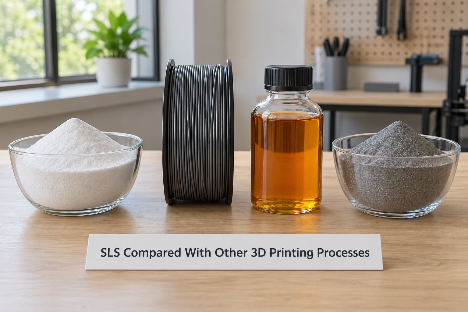
Against FDM, SLS wins on strength, accuracy and geometry while losing on cost, colour choice and the ability to print at home. Against SLA it wins on toughness, volume and batch economics while losing badly on surface finish and fine detail.
| Factor | SLS | FDM | SLA | MJF |
|---|---|---|---|---|
| Process | Laser sinters polymer powder in a heated bed | Melts thermoplastic filament | Cures photopolymer resin with a laser | Jets ink that wets and sinters powder |
| Support structures | Not needed | Usually needed | Required for most geometry | Not needed |
| Typical tolerance | Around +/-0.2 mm | Around +/-0.3 mm or worse | Around +/-0.1 mm or better | Around +/-0.1 to 0.2 mm |
| Surface as printed | Matte, grainy | Visible layer lines | Smooth, glass-like | Slightly smoother than SLS |
| Strength direction | Isotropic, tough | Weaker along layer bonds | Stiff but brittle | Isotropic, tough |
| Material range | Engineering polymers and filled grades | The widest range of any process | Many resins, some tough | Similar to SLS |
| Part size | Capped by build volume | Limited by bed size | Usually the smallest | Capped by build volume |
| Cost profile | Lowest per part when batched | Lowest equipment cost | Lowest for smooth cosmetic parts | Similar to SLS at scale |
| Best fit | Functional parts, tooling, short runs | Enclosures, concepts, low load parts | Cosmetic models, fine detail, patterns | Production batches, lighter grey tones |
SLS vs MJF: the modern sibling technology
Multi jet fusion works similarly, jetting liquid binder across a powder layer instead of scanning it with a laser. It shares SLS’s support-free geometry and tough parts, tends to give slightly finer detail and smoother surfaces, and batches parts more evenly across the bed, so consistency at high volume is its edge.
SLS keeps one advantage: it suits smaller batches, because a build does not need to be completely full before you pay for it. For a few dozen prototypes on a mixed powder, SLS is usually the cheaper and faster route. For thousands of identical production parts, MJF’s even layer distribution wins.
How to Choose an SLS Material for Your Part
Work through the service conditions before you look at price. Material choice is mostly an answer to five questions: how hot, how much load, how much flex, what chemicals, and how tight does it need to fit.
- Cool, low load, general purpose: PA 12. It handles most housings, brackets and ducting.
- Repeated flexing or a living hinge: PA 11 or TPU, depending on how soft you want it.
- Heat near or above 100 °C, or stiffness matters: carbon-fibre-filled PA, checking the filled grade’s heat deflection figure against your service temperature.
- Fluid contact or chemical exposure: PP for compatibility, or PA 12 once the fluid is verified.
- Machined faces and press fits: unfilled PA 12 or PA 11, and plan on machining those features rather than printing them to tolerance.
Two practical checks before you commit. Confirm the printed part is stiff enough and thin enough to flex, and run a small coupon or a critical-fit test first, because a snap fit that is 0.3 mm too tight fails on the first assembly attempt.
What Post-Processing Does an SLS Part Need?
Every SLS part needs depowdering. Everything after that depends on what you are trying to fix, and separating those two categories saves money.
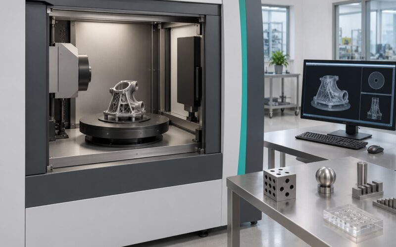
Required for fit, strength and production readiness: a dimensional check with calipers or a CMM on critical features, and thread or hole cleanup by tapping or boring if the part actually has threads. Also inspect for loose powder trapped inside enclosed channels before anything gets sealed.
Optional, for appearance: bead blasting smooths the grainy surface in seconds, dye colouring gives you a black, grey or coloured part without touching the surface itself, infiltration seals porosity for watertight or food-contact-adjacent applications, and a light machining pass on critical faces buys you tolerance without reprinting.
Clear coat sits at the end of that chain. It fills the remaining texture nicely for presentation parts, but on a wear surface it adds a film that can crack, so keep it off anything that flexes repeatedly.
How to Prepare a Part for SLS 3D Printing
A short design check before you upload saves a wasted build. These are the rules that catch most rejected first attempts.
- Set wall thickness to 1.5 mm minimum and rib anything thinner. 0.8 mm works for non-structural skins, not for load-bearing walls.
- Machine holes undersize by roughly 0.2 to 0.3 mm and let the supplier verify with a test coupon.
- Leave 0.2 mm clearance on sliding fits and be generous on snap fits; friction varies with powder and orientation.
- Give snap fits a root radius and a lead-in chamfer. A sharp internal corner concentrates stress and cracks the first time it snaps.
- Orient living hinges flat so the thin section prints as a thin layer, not as a vertical wall.
- Prefer printed-in geometry to threads where you can, and use heat-set inserts when real threads are unavoidable.
- Plan nesting. Spreading parts across the bed rather than stacking them shortens build time and drops the per-part cost.
- Flag anything questionable for a test build before committing to the full quantity.
Frequently Asked Questions
Is SLS 3D printing suitable for functional parts?
Yes, that is what it is best at. Sintered nylon parts are isotropic and tough, so they take handling, impact and repeated flexing far better than FDM prints with weak layer bonds. Engineers routinely use SLS for jigs, fixtures, grippers, brackets and end-use parts. Just design to the material: 1.5 mm minimum walls, clearance on fits, and a test build before committing to a batch.
Do SLS 3D printers need support structures?
No. The unsintered powder surrounding the part acts as the support structure, which is the main reason to choose SLS over FDM or SLA. Because of that, overhangs, bridges, internal channels and lattices print without scaffolding and nothing has to be cut off and cleaned up afterwards.
What is the difference between SLS and SLA 3D printing?
SLS sinters polymer powder with a laser and needs no supports, producing tough nylon parts with a matte, grainy finish. SLA cures liquid resin and needs supports for most geometry, producing smooth, detailed parts that are stiff and often brittle. Choose SLA for cosmetic models and fine detail, SLS for parts that get handled or loaded.
Can SLS parts be used for production?
Yes. Automotive interiors, orthotics, housings and consumer accessories all ship as SLS parts in real volumes. SLS suits short runs from a handful of pieces into the hundreds, where nesting many parts in one build spreads the machine cost. Above that point, MJF usually edges ahead on consistency per part.
How accurate is SLS 3D printing?
Typical dimensional tolerance is around +/-0.2 mm, which suits slip fits and clearance holes but not press fits or machined-style tolerance. Holes come out slightly undersize because heat pulls the powder in during fusing, so machine holes smaller in your model and confirm with a test build. Critical faces that need real tolerance are machined after printing.
Can SLS parts be painted or dyed?
Yes. Dye colouring soaks into the porous nylon surface and gives a strong colour without adding a coating, and parts can also be bead blasted for a smoother base or clear coated for a gloss finish. Both are appearance steps, not structural ones, so keep coatings off surfaces that flex repeatedly or the film can crack.
Conclusion
SLS 3D printing fits one job well: tough, dimensionally repeatable parts with geometry that support structures would ruin, made in quantities too small for a mould. It is the right first question to ask whenever your part gets handled in the real world rather than looked at.
Start by testing one part in PA 12, the default material, with 1.5 mm walls and clearance on every fit. Hold it, load it and check the surface against your expectation, then take the material choice from what you learn. That single test build settles most of the decisions that follow.