Post processing a metal 3D printed part means running it through a fixed sequence after it leaves the build chamber: depowder it, cut the supports off, relieve the residual stress thermally, machine the features that need tolerance, clean it, finish the surface, then inspect it. Metal additive manufacturing gives you a near-net-shape blank with rough, powder-dusted surfaces and locked-in internal stress, never a finished component. The whole workflow takes a few hours for a simple part and a few days if you outsource heat treatment or plating.
The order matters more than the individual techniques. Plenty of parts get sanded, polished or plated first and then warp when they hit the furnace or the machining centre, because the stress was never released. The routes below reflect shop practice as of 2026, and the alloy and the printer supplier’s own instructions always take priority over anything written here.
One warning before we start. Acetone vapour smoothing, plastic tumbling media and filler-filled polishing compounds are polymer techniques. They do nothing useful on metal and some of them contaminate a surface you were about to plate or anodize. If you have been reading a plastic post-processing guide, treat it as irrelevant until you read the metal-specific parts below.
Table of Contents
- 1What You Need
- 2Documentation and information
- 3Support removal
- 4Cleaning and inspection
- 5Personal protective equipment
- 6How to Post Process Metal 3D Printed Parts Step by Step
- 7How to Post Process Metal 3D Printed Parts: Remove Supports Safely
- 8Inspect the Raw Part
- 9Perform Stress Relief or Annealing
- 10Correct Dimensions and Critical Features
- 11Clean the Part Correctly
- 12Finish Functional and Cosmetic Surfaces
- 13Check Accuracy and Part Integrity
- 14Common Mistakes
- 15Tips for Repeatable Results
- 16Frequently Asked Questions
- 17What is the best way to finish metal 3D printed parts?
- 18Can you heat treat all metal 3D printed parts the same way?
- 19How do you remove supports without damaging the part?
- 20Is machining necessary for a metal 3D printed part?
- 21What surface finish should I choose for a functional metal part?
- 22How much dimensional accuracy should I expect after post processing?
- 23Conclusion
What You Need
Gather the tooling before the part comes out of the machine, because the correct order of operations depends on what you own. A shop with no furnace and no blast cabinet can still do most of the steps below; a few simply take longer or cost more outsourced.
Documentation and information
Start on paper, not on the part. You need the alloy and its data sheet, the printer supplier’s recommended post-processing route, the build orientation, the intended machining allowance on critical features, and the tolerance and surface finish the drawing calls for. Without those five things you are guessing, and guessing here means distorted parts.
Support removal
A flush-cut band saw or a disc cutter with a dedicated carbide blade, a high-speed die grinder with tungsten carbide or diamond burrs, and a carbide or HSS file set. A wire EDM machine is the expensive, zero-contact option if the supports are delicate or the part is a nickel superalloy with a poor machinability rating.
Cleaning and inspection
Bead blasting cabinet with a lined abrasive belt and a filtered dust collector, ultrasonic cleaner, compressed air with a filter, brass wire brush, nylon brushes, calipers, and access to a coordinate measuring machine for anything tolerance-critical. A dye penetrant kit is worth having for checking machined surfaces and welds. Add an argon-compatible vacuum furnace for thermal work, or a supplier who runs one.
Personal protective equipment
Safety glasses, cut-resistant gloves for handling, a respirator rated for metal powder during depowdering, and a dust-tight cabinet for anything that generates fine particulate. Metal powders are combustible, and the fine fraction from a blast cabinet is no exception. Gloves and loose sleeves near a rotating burr cost you a fingertip.
How to Post Process Metal 3D Printed Parts Step by Step
Run the steps in this sequence. Each one exists to make the next one safer or more accurate, and skipping ahead is where distortion and rework come from.
How to Post Process Metal 3D Printed Parts: Remove Supports Safely
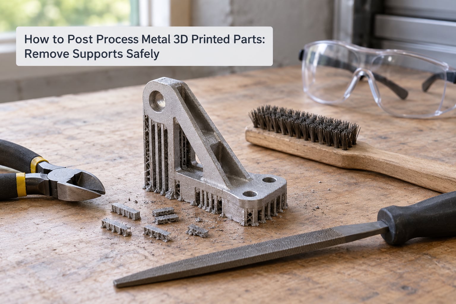
Find an access path for your cutting tool before you cut anything, and work back from the support structure toward the part rather than the other way around.
- Read the orientation. The as-built orientation tells you where the support interfaces sit and roughly which surfaces were facing the plate. Downward faces near the build plate carry the deepest supports and usually the roughest surviving surface.
- Clear the powder first. Blow out loose powder with filtered compressed air and a stiff brush before any cutting. Powder trapped under a support turns into a grinding-wheel clog two seconds into the job.
- Cut with a thin, sharp tool. A flush-cut band saw or a dedicated carbide blade gives the cleanest separation and the flattest support scar. Leave a thin witness of support material rather than cutting flush; you can dress it off after the part is stress relieved.
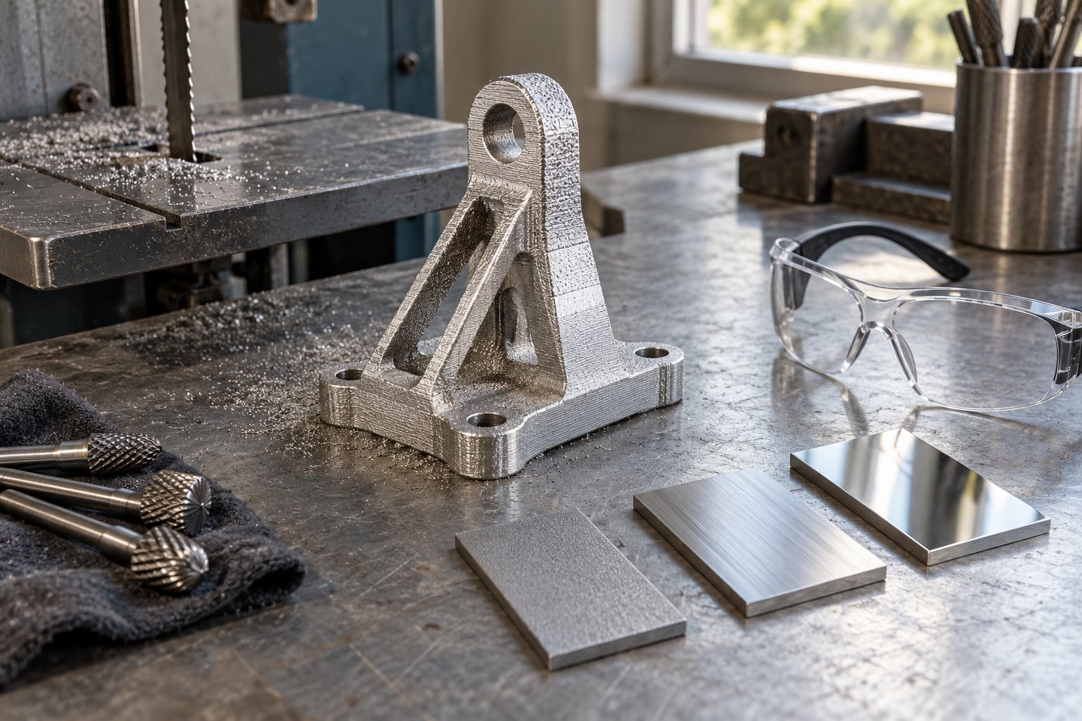
- Grind the attachment scar. Work the remaining stub with a carbide burr or a diamond file, holding the tool at a shallow angle and letting it cut rather than burnish. Take short passes and cool frequently. Grinding generates heat, and heat on a still-stressed part is how you lose flatness.
- Hand-finish where it matters. Where a support attached to a sealing face, a bearing seat or a mating flange, use a file and laps by hand. Those are the surfaces you will not be able to recover later.
- Verify nothing is left. Check under the part, inside every overhang and along every channel with a flashlight and an inspection mirror. Trapped support fragments and loose powder are the most common reason a part fails at assembly rather than at the bench.
Two habits separate a good support-removal job from a rushed one. Keep the cutting area bright and take the swarf away as you go, and put each part on a labelled fixture or mark so you know its orientation later. The second one saves you when you have four identical brackets and one drawing.
Inspect the Raw Part
Photograph and measure the part before you make any irreversible change to it. This is the only baseline you get.
Record overall and critical dimensions with calipers or a micrometer, note the depth of the layer lines and the roughness of a face that matters, and mark every visible defect: lack-of-fusion marks, spatter, keyholing, delamination at a former support interface, and any layer that lifted. On a bracket going into a prototype build, I photograph each face flat and straight on so distortion shows up as a straight-line mismatch rather than a guess later.
Decide now which faces get machined and which stay as-built. That decision drives the rest of the job, and it is much harder to reverse after you have blasted or polished the part.
Perform Stress Relief or Annealing
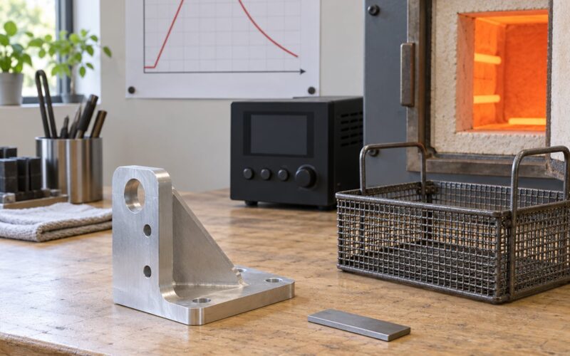
Residual stress in a printed part comes from the metal being heated and cooled thousands of times a second during the build, and from the steep thermal gradients between the hot interior and the cooler surface. A stress-relief cycle reheats the whole part and lets the locked-in stresses redistribute, which is why a part that was warped on the plate often comes out of the furnace visibly straighter.
The parameters depend entirely on the alloy and on the geometry, and your printer or service bureau’s published route outranks any generic figure. Use the data sheet’s stress-relief temperature and soak time, hold the part so it heats evenly, and ramp up and down slowly enough that the thermal gradient never gets a chance to distort it.
- Aluminium alloys such as AlSi10Mg are typically stress relieved at a few hundred degrees Celsius for a couple of hours, then left to cool in the furnace.
- Stainless steels like 316L and 17-4PH take a higher stress-relief temperature, and 17-4PH is usually age hardened afterwards with a separate solution-temper-and-age cycle.
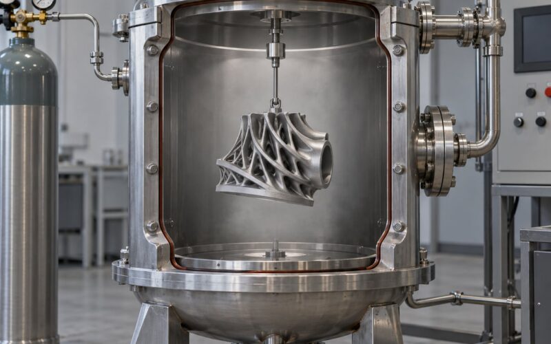
- Titanium Ti-6Al-4V has low conductivity and a high oxidation sensitivity, so it needs a controlled argon atmosphere and a slow ramp.
- Nickel superalloys such as Inconel 625 and 718 are work-hardening and crack-prone, and the stress-relief window is narrow and temperature-sensitive.
Annealing goes further than stress relief. It fully recrystallises the as-built microstructure, giving better ductility and toughness and removing martensite from steels that cooled too fast, at the cost of the strength the fast solidification gave you. Engineers working in structural analysis forums make this point often enough: use the post-processed properties, not the as-built ones, or the finite element results will not match the real part.
Hot isostatic pressing closes internal porosity and is a qualification step for aerospace, energy and medical work, not a routine one. It subjects the sealed part to high gas pressure at temperature, so it needs specialist equipment and adds days. Most shops send it out.
Correct Dimensions and Critical Features
Machining is only worth it where the function demands it: bearing bores, mating flanges, datum faces, threaded holes, sealing surfaces. Printing leaves you close on geometry and far from surface quality, so the right instinct is to design the part with an allowance on those few features and leave everything else alone.
Mill, turn, drill, ream or grind according to the feature. The critical constraint is sequencing. Cut rough material first and leave a finishing pass, because a heavy cut releases more stress than a light one. Thin walls distort if you take a full-width facing pass over them, so rough with a lighter tool and generous stepover, then stress relieve again if the part is heavily machined or the distortion shows up in the measurements.
Keep a machining allowance of roughly half a millimetre per side on critical features as a starting point and adjust for your machine, material and geometry. On difficult alloys, raise it, because more removal means more final control. Record the as-machined dimensions and hold the part to a clean tolerance for anything that mates or seals.
Clean the Part Correctly
Cleaning is where parts quietly go wrong. Choose the method for the contaminant, and never carry a cutting-fluid film into an anodize or plating tank.
- Loose powder and support fragments: filtered compressed air, stiff nylon brush, then ultrasonic cleaning in a solvent compatible with the alloy. Stainless and nickel tolerate standard aqueous ultrasonic degreasers; aluminium and copper need care, and chloride-containing cleaners pit stainless if it stays in contact too long.
- Grease, fingerprints and cutting fluid: aqueous alkaline detergent and ultrasonic, followed by a rinse that will not leave a watermark.
- Oxide scale and heat-treat residue: mechanical removal or a pickled surface before plating, since scale blocks adhesion.
Use argon or a proper vacuum purge for internal channels rather than trying to blow powder out with air alone. Air flowing through a partially blocked passage just packs the powder tighter at the far end, which is how you end up discovering a compacted plug during assembly.
Finish Functional and Cosmetic Surfaces
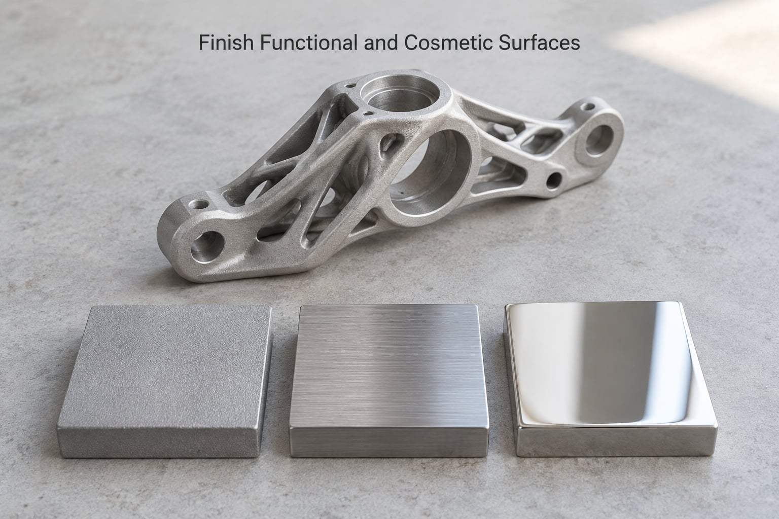
Pick the finish from the part’s job. A mating face, a seal or a fatigue-critical surface wants a roughness number. A presentation part wants an appearance. The two rarely need the same route, and chasing a mirror finish on a sealing surface wastes money and material.
Bead blasting with glass or ceramic bead at 50 to 125 micrometres takes the layer lines off and leaves a matte surface across most alloys. It is also the standard first cleaning step for as-built parts, and the consensus on machining forums is blunt about it: sandblast first, because nothing else you do afterwards will remove the trapped powder and as-built oxidation the way a blast cabinet does. In r/3Dprinting, that is the default recommendation for anyone with a decent compressor and a cabinet, with tumbling as the cheaper option when they do not.
| Finishing method | Typical result | Cost and turnaround | In-house practical |
|---|---|---|---|
| Bead or ceramic blasting | Uniform matte surface, layer lines removed, Ra roughly 1.6 to 6.3 micrometres | Low, minutes per part | Yes with a cabinet and a compressor |
| Vibratory or barrel finishing | Rounded edges, modest Ra improvement, consistent on many parts at once | Low, hours of cycle time | Yes, and metal media only |
| Hand sanding and polishing | High gloss on flat accessible areas | Lowest cost, highest labour | Yes, but it will not reach internal channels |
| Electropolishing | Bright, smooth, low Ra, removes a small amount of material and burrs | High, days of turnaround | No, send it out |
| Anodizing (aluminium) | Hard oxide surface, corrosion and wear resistance, dyeable colour | Moderate, colour depends on the dye bath | No, tank and dye bath required |
| Electroplating or powder coating | Corrosion protection, wear layer, appearance, controllable thickness | Moderate to high, plus masking and rack time | No, plating line required |
Tumbling and vibratory finishing use metal media on metal parts. Ceramic media works too, but never plastic media: it embeds in the surface and contaminates any later plating or passivation step. Keep the fill level and cycle time consistent, because finish quality varies more with those two variables than with the media itself.
Electropolishing is the route to a bright, near-mirror finish on complex geometry. It removes a very thin layer, so it hides surface defects less than hand polishing does, which means the surface has to be prepared properly first. Common consensus on forums is that blasting, then tumbling, then electropolishing beats any single step attempted on the raw as-built surface.
For heat exchanger and medical applications, finish matters for the function, not the look. Internal channels must be clean enough to flow, corrosion-resistant enough for the environment, and free of loose powder. On a medical implant the surface condition and the cleaning validation are part of the qualification, and a DIY finish has no place in that path.
Check Accuracy and Part Integrity
Inspect against the drawing, not against how the part looks. Calipers and micrometers cover everyday features; anything tolerance-critical goes on a coordinate measuring machine, and internal geometry goes to a CT scanner if you need non-destructive evidence.
Check critical dimensions and datums, and confirm that mating features meet their tolerance after the heat cycle, not before it. Look for cracks with dye penetrant testing on machined surfaces and stress concentrations, and check for warpage by comparing flat surfaces against a surface plate. Verify coating thickness where a coating carries the corrosion requirement, using a magnetic thickness gauge on ferrous parts and eddy current on non-ferrous ones.
Then do the functional checks: fasteners thread cleanly and pull to torque, seals hold, a shaft fits the bore with the clearance you designed, and nothing moves where it should be fixed. For regulated work, keep the material certification, the heat treatment record and the inspection results with the part. Traceability is part of finishing, not paperwork you add later.
Common Mistakes
Skipping stress relief. The part distorts when you cut it, or cracks at a support interface. Fix: stress relieve before support removal is aggressive but effective; the safer order is remove supports, then relieve, then measure.
Machining without a machining allowance. You have nothing left to cut on a critical feature and the part is scrap. Fix: design the allowance in, and never treat the printed surface as a finished datum.
Using aggressive abrasives on thin walls or sharp features. Abrasive blasting rounds sharp edges, notches thin sections and erases detail. Fix: match the media to the geometry and mask or protect delicate areas.
Cleaning with incompatible chemicals. Chloride cleaners pit stainless, and acidic treatments attack titanium and aluminium. Fix: check the alloy against the chemical and follow its safety data sheet.
Plating or anodizing before stress relief. The coating then crazes or flakes when the part moves. Fix: all thermal work first, all coatings last.
Rounding sharp corners during finishing. Blasting and tumbling remove material from edges faster than from faces. Fix: if an edge is a functional feature, machine it after abrasive finishing or mask it.
Ignoring trapped powder in internal channels. The part is fine until assembly, then a channel is blocked or a plug breaks loose downstream. Fix: design for powder removal, flush with gas or ultrasonic, and check before the part leaves.
Tips for Repeatable Results
Write a routing sheet per part family: alloy, orientation, stress relief parameters, machining features and allowance, finishing route, inspection points. Half an hour here saves a whole scrapped batch later.
Control heat rather than chasing it. Slow ramps, controlled atmosphere, uniform part spacing inside the furnace and a consistent cooling path give you a repeatable result more reliably than a tighter final tolerance will.
Protect the datums. Designate the faces that define the part, treat them as no-go zones for blasting media, and make sure nothing in the route puts an edge on a sealing surface. Label every part at every stage, and stage tools in a fixed order so the same operator produces the same result on a different day.
Finally, measure the route rather than guessing at it. Track rework causes: distorted parts, coating adhesion failures, powder left behind. Two data points from the same part family will tell you more than a month of guessing where the process is weak.
Frequently Asked Questions
What is the best way to finish metal 3D printed parts?
Bead blasting with glass or ceramic bead is the best general-purpose finish: it removes layer lines, knocks off trapped powder and as-built oxide, and gives a uniform matte surface on almost every alloy. For a brighter result, follow with vibratory or barrel finishing, then electropolish if you need near-mirror. Match the method to the function rather than the look, since sealing and fatigue-critical faces need a roughness number, not a gloss.
Can you heat treat all metal 3D printed parts the same way?
No. Heat treatment is alloy-specific and geometry-sensitive. Aluminium alloys and stainless steels stress relieve at different temperatures, titanium needs a controlled argon atmosphere because of its oxidation sensitivity, and nickel superalloys have a narrow, crack-prone window. Age-hardening steels such as 17-4PH need a separate solution temper and age cycle after stress relief. Always follow the alloy data sheet and your printer supplier’s published route.
How do you remove supports without damaging the part?
Clear loose powder with filtered air first, then cut with a flush-cut band saw or a thin carbide blade, working from the support structure toward the part and leaving a small witness stub. Dress the scar off with a carbide or diamond burr held at a shallow angle, in short passes with frequent cooling. Hand-file any support attachment that sits on a sealing face or bearing seat, then check under the part and inside every channel with an inspection mirror for fragments and loose powder.
Is machining necessary for a metal 3D printed part?
Only where function demands it. Printing holds geometry reasonably well but not surface quality, so machine bearing bores, mating flanges, datum faces, threaded holes and sealing surfaces, and leave everything else as-built. Design a machining allowance of roughly half a millimetre per side on those features, take rough cuts before finishing passes, and measure again after heat treatment because machining and thermal cycles both release stress.
What surface finish should I choose for a functional metal part?
Choose by function, not appearance. Bead blasting usually lands in the 1.6 to 6.3 micrometre Ra band and is fine for non-critical bodies. Sealing faces and press fits need smoother, more consistent roughness from tumbling or precision grinding. Fatigue-critical surfaces deserve the smoothest finish you can afford, because surface defects act as crack initiation sites and cut fatigue life sharply. Cosmetic parts can stay at as-built or blasted.
How much dimensional accuracy should I expect after post processing?
As-built metal parts are near-net-shape but carry variation from thermal distortion during the build, so anything tolerance-critical needs machining. Whether you are within tolerance as-built depends on size, alloy and orientation, which is why measuring before and after is standard practice rather than optional. Post processing can improve accuracy where stress relief straightens a warped part, but coatings and finishing add material, so specify the final condition your drawing actually requires.
Conclusion
Post processing metal 3D printed parts is a sequence, and the sequence is the whole trick: document the as-built part, remove supports cleanly, relieve the residual stress thermally, machine only the features that need tolerance, clean for the alloy, finish for the function, and inspect against the drawing. Skipping the thermal step or moving a coating earlier than a heat cycle is the single mistake that warps more parts than anything else on the bench.
Start by identifying four things: the alloy, the geometry, the performance requirement, and your printer supplier’s recommended post-processing route. Everything else in this guide follows from those four answers, including which steps you run yourself and which you send out to a service bureau.