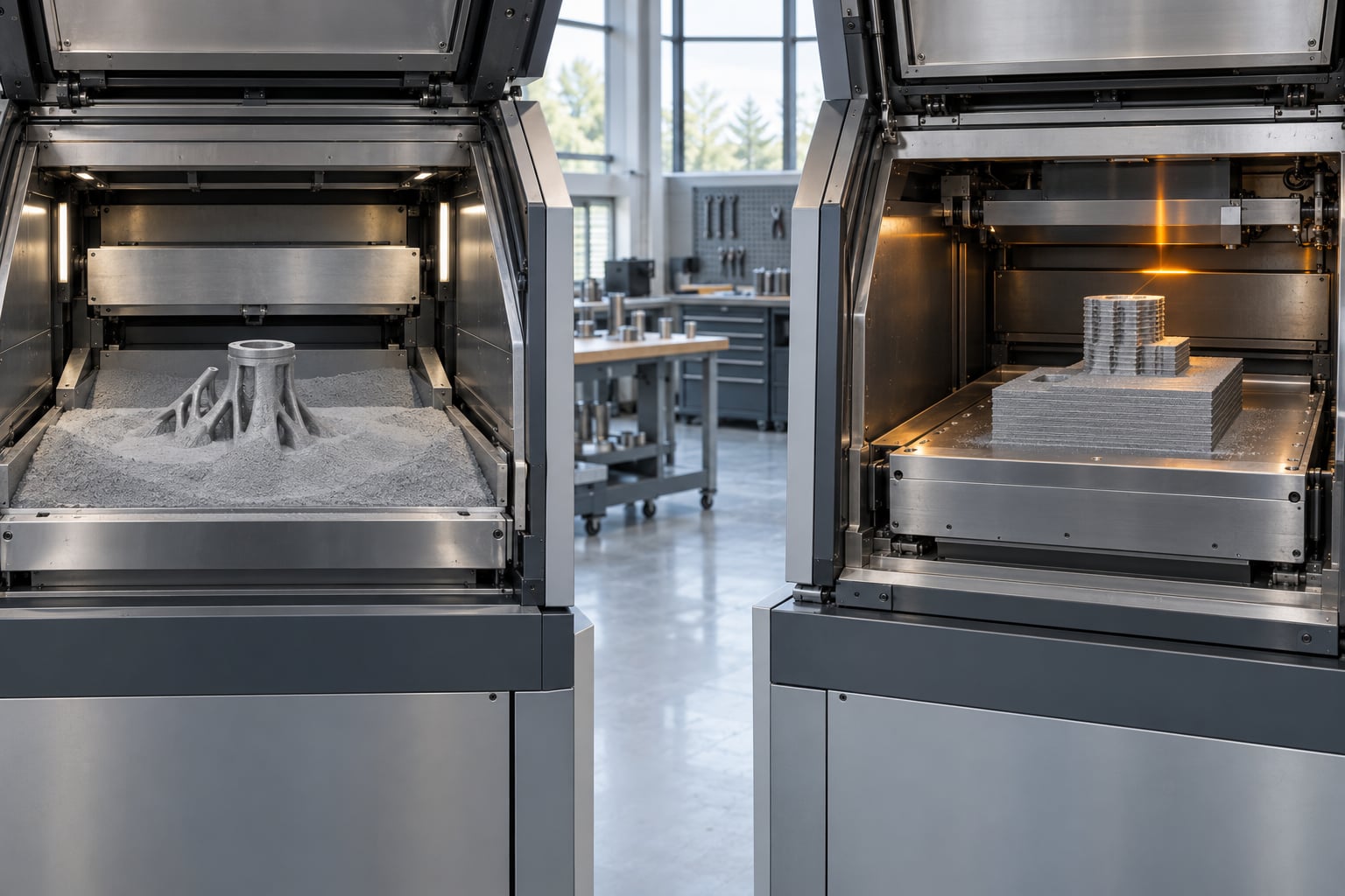
DMLS and SLM are the same metal 3D printing process under two vendor names. DMLS stands for Direct Metal Laser Sintering and belongs to EOS; SLM stands for Selective Laser Melting and belongs to SLM Solutions. The ISO/ASTM 52900 standard calls the process laser powder bed fusion for metals, written PBF-LB/M. Both describe a fibre laser melting metal powder layer by layer inside an argon chamber.
That is the short answer, and it is the one that trips up almost everyone new to metal additive manufacturing. The confusion is not your fault. The two acronyms came from two different company lineages, both from the 1990s, and both got stuck in the vocabulary of brochures, job specs and academic papers before any standard existed to sort them out.
The interesting part is what the labels hide. They sound like they describe two different physical behaviours, one that sinters and one that melts. In modern machines, both fully melt the powder, and parts from either can reach relative density above 99 percent. What genuinely varies is the hardware: laser power, laser count, spot size, layer thickness, atmosphere, plate preheat and build volume. This guide walks through those differences, then gives you a way to choose that does not depend on whose acronym is on the machine.
Updated for October 2026.
Table of Contents
- 1What Is DMLS and How Is It Different from SLM? at a Glance
- 2How DMLS and SLM Build Metal Parts
- 3What is DMLS, step by step?
- 4Where the chambers actually differ
- 5DMLS vs. SLM: Materials and Chemical Composition
- 6DMLS vs. SLM: Surface Finish, Detail, and Accuracy
- 7DMLS vs. SLM: Strength, Heat Treatment, and Mechanical Properties
- 8DMLS vs. SLM: Cost, Speed, and Production Considerations
- 9Which Should You Choose?
- 10Frequently Asked Questions
- 11Are DMLS and SLM the same process?
- 12Which process produces smoother metal parts?
- 13What materials can DMLS print compared with SLM?
- 14Is DMLS stronger than SLM?
- 15Which is cheaper for low-volume metal parts?
- 16How do I choose between DMLS and SLM for production?
- 17The Short Version to Take Into a Design Review
What Is DMLS and How Is It Different from SLM? at a Glance
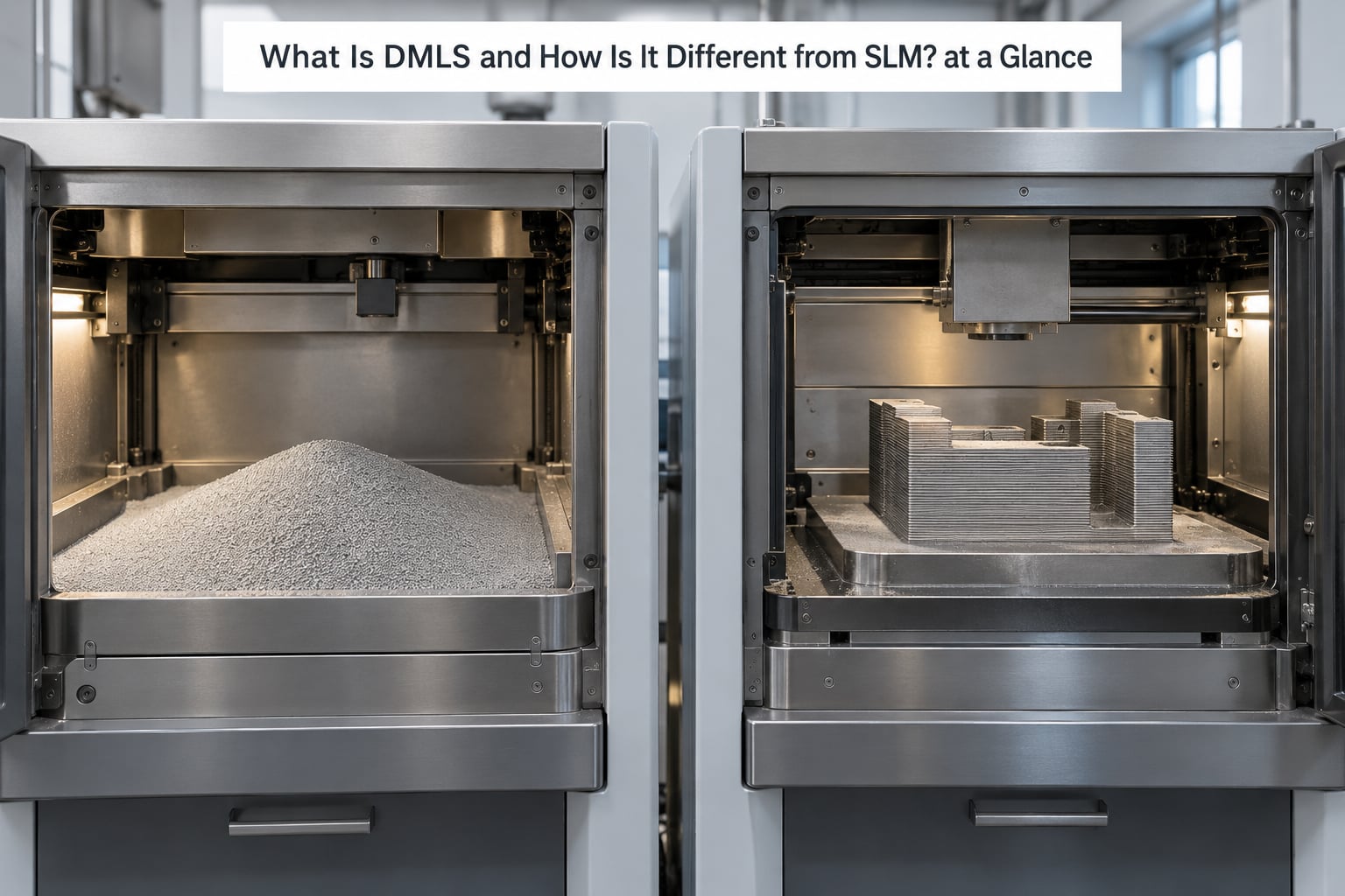
The cleanest way to see the difference is to compare them on the things a part actually depends on. Here is the short version; the sections below unpack each row.
| Criterion | DMLS | SLM |
|---|---|---|
| Working principle | Fibre laser melts metal powder layer by layer | Fibre laser melts metal powder layer by layer |
| Standard term | PBF-LB/M (ISO/ASTM 52900) | PBF-LB/M (ISO/ASTM 52900) |
| Trade name owner | EOS | SLM Solutions |
| Powder support | Self-supporting; the loose powder bed supports the part | Self-supporting; the loose powder bed supports the part |
| Layer bonding | Full melt, metallurgical fusion between layers | Full melt, metallurgical fusion between layers |
| Materials | Stainless, tool steels, titanium, aluminium, nickel superalloys | Same families; machine-specific parameter sets decide availability |
| Typical layer thickness | 20 to 60 micrometres | 20 to 60 micrometres |
| As-built surface finish | Rough, Ra around 6 to 12 micrometres | Rough, Ra around 6 to 12 micrometres |
| As-built accuracy | About plus or minus 0.1 to 0.2 mm | About plus or minus 0.1 to 0.2 mm |
| Relative density | Above 99 percent with validated parameters | Above 99 percent with validated parameters |
| Strongest applications | Fine detail, thin walls, complex internal channels | Thicker parts, certified alloys, fatigue-critical work |
Read the table honestly and the conclusion is unavoidable: on every physical property, the two rows say the same thing. The final row is the only one that reflects a real preference, and that preference comes down to which parameter set a supplier has validated on their own machine, not to the acronym.
How DMLS and SLM Build Metal Parts
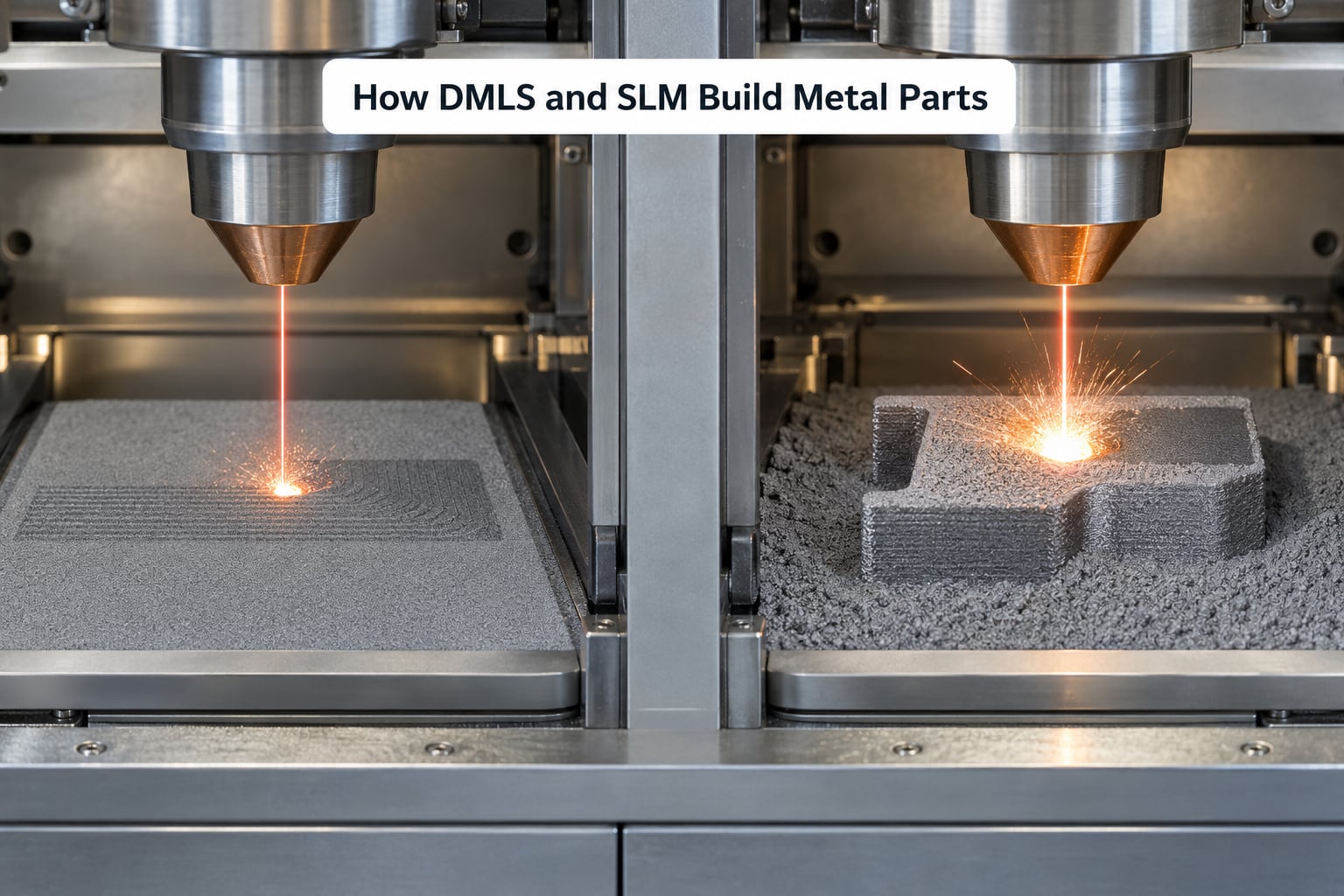
Both processes run the same five-step cycle inside a sealed chamber filled with argon or nitrogen. The laser is a fibre laser, usually in the range of a few hundred watts to around a kilowatt, focused to a spot somewhere between 50 and 150 micrometres across.
What is DMLS, step by step?
- Deposit. A recoater blade spreads a fresh layer of fine metal powder across the build plate, typically 20 to 60 micrometres thick.
- Scan. The fibre laser scans the cross-section defined by the slice file, melting those particles completely and fusing them to the layer below.
- Lower. The platform drops by one layer thickness and the recoater spreads the next layer of powder.
- Repeat. Steps one to three run until the full build height is reached, which on a large machine can take days.
- Finish. The plate is removed, the part is broken out of the powder cake, then stress relieved or heat treated, optionally hot isostatic pressed, and machined where precision is needed.
Where the chambers actually differ
The argon atmosphere is the same for both, and oxygen levels near a part in the tens of parts per million are the usual target. The differences sit in the chamber hardware: how much laser power is available, how many lasers are mounted, how the plate is preheated to manage residual stress, and how large the build volume is. A machine with four lasers covers the same area faster than a single-laser machine, which matters when you are quoting a lead time.
Plate preheat is worth a second look. Preheating the build plate reduces thermal gradients through the part as it grows, which is one of the main ways an operator limits distortion in tall, thin geometries.
DMLS vs. SLM: Materials and Chemical Composition
Both processes run the same alloy families, and in practice a given machine will support a subset of them. The practical question is never what DMLS can print in theory. It is what the supplier in front of you has validated.
Stainless steel is the common entry point, with 316L the most widely used grade for prototypes, medical tooling and hardware. Tool steels such as maraging and 17-4PH cover mould inserts and functional parts that need hardness. Titanium alloys, Ti-6Al-4V above all, dominate orthopaedic implants and aerospace brackets because of the strength-to-weight ratio and the biocompatibility of the oxide surface.
Aluminium alloys such as AlSi10Mg and AlSi12 appear in lightweight brackets and thermal hardware. Nickel superalloys, Inconel 718 and Hastelloy grades among them, run hot, so they show up in turbine and combustor hardware and in tooling that has to survive a furnace. A handful of machines add refractory metals, copper alloys and even gold for dental and jewellery work.
Chemical composition is where the standards do the heavy lifting. Buyers increasingly specify alloys by ASTM F42 specification rather than by nickname: F3184 for 316L, F2924 for Ti-6Al-4V, F3055 for Inconel 718, F3318 for AlSi10Mg. Naming the alloy that way ties the purchase order to a qualification route your quality team already understands.
DMLS vs. SLM: Surface Finish, Detail, and Accuracy
As-built surfaces on either process are rough, typically Ra 6 to 12 micrometres, and the stair-stepping you can see on a curved wall is simply the layer stack. Dimensional accuracy as-built sits around plus or minus 0.1 to 0.2 mm. If a supplier quotes ten-micron tolerances, they are talking about machined features after heat treatment, not about the raw printed surface.
Four machine variables drive the finish you get, and they apply to DMLS and SLM alike:
- Layer thickness. Thinner layers reduce the step height on angled and curved faces.
- Laser spot size. A smaller spot can resolve finer features and narrower channels, at the cost of a slower scan.
- Powder particle size. Finer powder flows more evenly and reduces surface roughness, but spreads less safely and is more expensive.
- Scan strategy and hatching. How the toolpath fills a cross-section changes how heat distributes and therefore how the part distorts.
This is the honest reason DMLS has a reputation for detail work. Machines optimised for fine resolution tend to carry smaller lasers, smaller build volumes and premium powder. Multi-laser systems trade some of that resolution for speed. That is a hardware choice a supplier made for a market segment, not a rule written into the acronym.
DMLS vs. SLM: Strength, Heat Treatment, and Mechanical Properties
For the same alloy and comparable parameters, a DMLS part and an SLM part of similar density have comparable mechanical properties. Anyone claiming one is systematically stronger is pattern-matching on a brand name. Density, anisotropy, residual stress and post-processing decide the numbers, not the label.
Porosity is the topic most newcomers ask about first, and it is worth being precise. Validated parameter sets reach above 99 percent relative density. The remaining voids come from two families: lack-of-fusion porosity, where the laser energy was too low to join particles, and keyhole porosity, where the energy was too high and the melt pool boiled a gas bubble into the part. Both are parameter problems, not process problems, and both are detected by metallographic sectioning or CT scanning during qualification.
For fatigue-critical and pressure-critical work, hot isostatic pressing closes residual internal porosity. It is slow and expensive, but it removes the defect sites that initiate cracks under cycling.
Residual stress is the other quiet variable. Each layer cools and contracts, and a tall part accumulates locked-in tension that can distort it during stress relief or crack it outright. Supports, print orientation and a proper stress-relief cycle exist to manage exactly this. Neither acronym removes that problem for you.
DMLS vs. SLM: Cost, Speed, and Production Considerations
Neither name changes what a part costs. What changes the cost is machine time, material and finishing, and those move in ways a buyer can plan for.
- Machine time. You pay for the whole build cycle, not just the time your part is being scanned. Nesting several small parts into one build spreads the fixed cost.
- Powder. Metal powder is expensive and has a shelf life. Reuse ratios and refresh rates affect the cost of the material in your part.
- Supports and orientation. A part laid out badly needs more support, more material removal and more finishing labour.
- Post-processing. Stress relief, solution treatment and ageing, HIP, machining, blasting and surface treatments all add to the cycle. For steel, hot forging or peening may be specified on fatigue-critical parts.
- Inspection. Material certificates, density verification and any qualification testing sit outside the machine cost entirely.
On lead time, a single part can move from a design file to a finished component in a couple of weeks when a machine is free, and far longer during a queue. For prototypes, complex internal channels and low volumes, laser powder bed fusion of either name is usually the only sensible route to a metal part. For larger production quantities, the economics shift toward casting or machining, and a service bureau is usually the right place to run the comparison for you.
Which Should You Choose?
Here is how I would frame the decision for a team that has to place real orders.
Choose the supplier, not the acronym. Ask what alloys they run, what their tolerance and surface-finish capability is after machining, and whether they can supply a material certificate and density verification for your material. That answers every question the acronym was supposed to answer.
Pick DMLS-labelled machines when detail is the hard part. Fine channels, thin walls, small features and as-built surface quality are what separates one laser machine class from another, and it is where supplier focus usually is.
Pick SLM-labelled machines when certification is the hard part. Aerospace and medical programmes often want a specific machine platform with an established qualification file behind it, and those programmes tend to cluster around SLM Solutions hardware.
Ignore the name when the part is heavy and the run is long. Large brackets and structural parts may need to be split, joined and machined anyway, and a casting may win on both cost and lead time.
Frequently Asked Questions
Are DMLS and SLM the same process?
Physically, yes. DMLS is the EOS trade name and SLM is the SLM Solutions trade name for the same laser powder bed fusion process, which ISO/ASTM 52900 classifies as PBF-LB/M. Both use a fibre laser to fully melt metal powder layer by layer in an inert argon chamber, and both reach above 99 percent relative density with validated parameters. The difference in parts comes from machine hardware and parameter sets, not from the name.
Which process produces smoother metal parts?
Neither, on the label. As-built surface finish on DMLS and SLM both fall around Ra 6 to 12 micrometres, limited by layer thickness, laser spot size and powder particle size. Machines configured for fine resolution can reach the lower end of that range, but the deciding factor is the hardware and parameter set, not whether the supplier calls it DMLS or SLM. Smooth functional surfaces need machining after printing.
What materials can DMLS print compared with SLM?
The same families: stainless steels such as 316L, tool steels including 17-4PH, titanium alloys such as Ti-6Al-4V, aluminium alloys such as AlSi10Mg, and nickel superalloys such as Inconel 718, with some machines adding refractory metals and copper alloys. Availability is supplier-specific, since each alloy needs a validated parameter set. Ask the machine operator what they run and what specification they can certify to, such as ASTM F3184 or F2924.
Is DMLS stronger than SLM?
For the same alloy at comparable density and with the same post-processing, the mechanical properties are effectively the same, because both processes fully melt the powder. Density, porosity, residual stress, orientation and heat treatment decide strength, not the acronym. For fatigue-critical parts the sensible comparison is between two suppliers on the same specification, including HIP and testing, rather than between the two names.
Which is cheaper for low-volume metal parts?
Neither acronym carries a price difference. For low volumes the cost drivers are machine time across the full build cycle, how well your part nests with others, powder volume and reuse, support material, and the finishing steps such as stress relief, HIP, machining and inspection. Laser powder bed fusion under either name is typically the only practical route for one-off metal parts with complex geometry. For larger runs, compare against casting and machining before committing.
How do I choose between DMLS and SLM for production?
Choose by requirement, not by name. If your priority is fine detail, thin walls or as-built surface quality, look at machines configured for resolution. If it is a certified alloy in a qualified process, look for a machine platform with an existing qualification file. Then require a material certificate, a stated tolerance after machining, and a density verification method on the purchase order, and write the process as laser powder bed fusion per ISO/ASTM 52900.
The Short Version to Take Into a Design Review
DMLS and SLM describe one process, and the parts differ because of the machine, the parameters and the finishing, not the acronym. Write laser powder bed fusion on the drawing, name the alloy by its ASTM specification, state the tolerance you need after machining, and ask for a material certificate and density verification. Everything else is a conversation about hardware, and that is a conversation you can win.