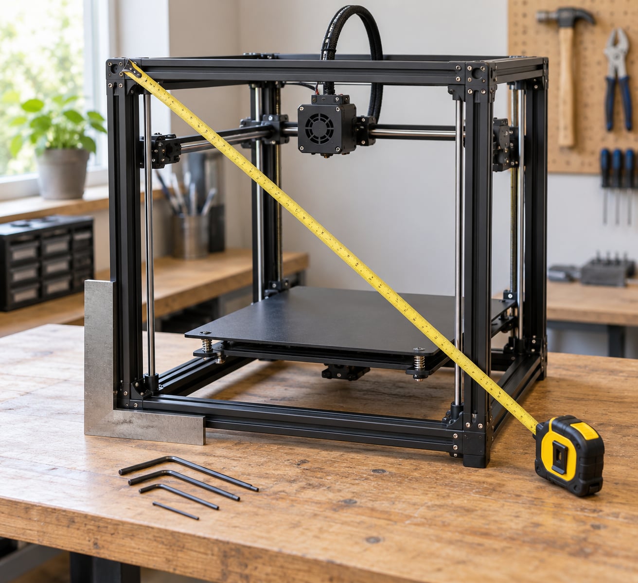
To square a 3D printer frame, measure both corner-to-corner diagonals, loosen the frame bolts about half a turn so the extrusion can settle, nudge the corners until the two diagonals match, then tighten again in a defined order while checking with a machinist’s square. That diagonal difference is your out-of-square error.
Most machines arrive close enough to square to print a decent part. Trouble shows up months later, after a move, a collision, or a bracket that got overtightened. Then squares print as rhombuses, circles as ovals, and one corner of a tall part lifts away from the bed.
One thing to sort out before you touch a bolt: the frame and the gantry are separate problems. The frame is the structure that holds everything. The gantry is the moving X carriage bolted onto it. Lots of searches for frame squaring are really about a gantry sitting out of level, and those are fixed with different hardware. You will know which one you have as soon as you measure.
Table of Contents
- 1What You Need
- 2How to Square a 3D Printer Frame Step by Step
- 3How to Square a 3D Printer Frame: Start with Equal Diagonals
- 4Loosen the Joints Without Removing the Frame
- 5Equalize the Frame Width and Height
- 6Correct the Remaining Diagonal Difference
- 7Tighten and Recheck the Frame
- 8Mistakes to Avoid While Adjusting
- 9Verify the Repair Before Printing
- 10Common Mistakes and How to Correct Them
- 11Frequently Asked Questions
- 12How much diagonal difference is acceptable on a 3D printer frame?
- 13Do I have to loosen the whole frame to square it?
- 14Why do my diagonals still differ after I check with a machinist’s square?
- 15Should I square the frame or the gantry?
- 16How do I know if my frame is warped beyond a simple fix?
- 17Do I need to recalibrate after squaring the frame?
- 18Conclusion
What You Need
Most of the tool list is cheap and some of it you already own. The manufacturer’s manual matters more than people expect, because bolt order and torque values are machine-specific and change between hardware revisions.
- The manual for your exact model and hardware revision. Bolt loosening order, torque values, and any stated squareness tolerance live here.
- A tape measure or steel rule accurate to about 1 mm. This is enough for the diagonal method on a printer under 500 mm wide.
- A machinist’s square, also sold as an engine square or try square. A plastic drafting triangle is not accurate enough for this job.
- A straightedge. For checking whether a corner bracket or an extrusion face is bent.
- Digital calipers. For the gantry gap measurement and for verifying test prints.
- The hex keys or driver bits the printer came with. A small torque driver is useful but not essential.
- A flashlight. For seeing gaps and daylight between mating surfaces once joints are loose.
- Feeler gauges, optional. Only needed if you get to sub-millimetre correction with shims.
Before anything else, print or find a test object for the machine. A 20 mm calibration cube and a three-square test pattern give you a before and after picture that no amount of guessing will.
How to Square a 3D Printer Frame Step by Step
The whole job is one loop: measure, loosen, nudge, measure again, tighten, re-measure. The frame has to be loose to move and tight to stay, and the measurement has to be repeated after every change because tightening itself shifts things.
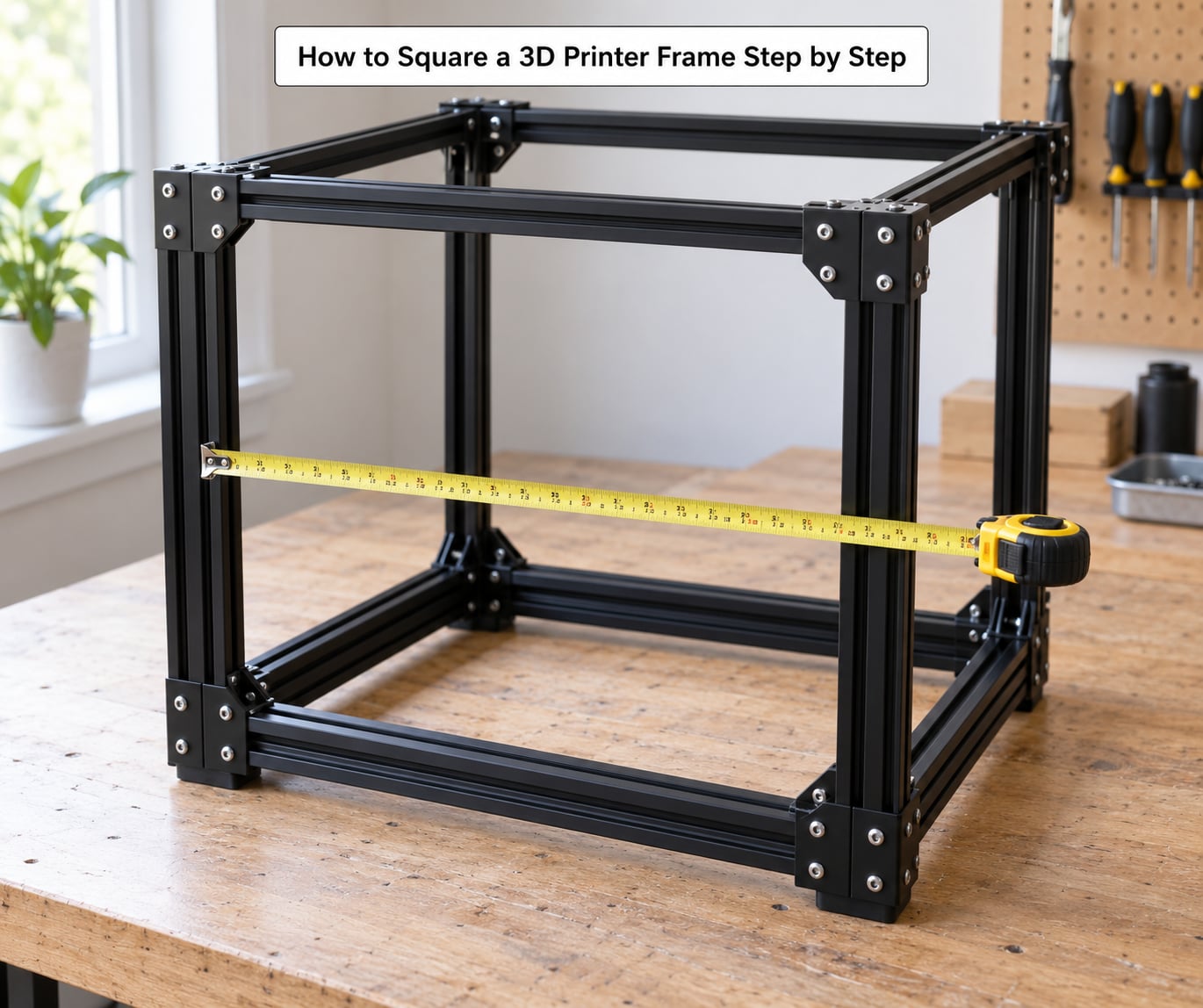
How to Square a 3D Printer Frame: Start with Equal Diagonals
Measure corner to corner twice, once each way, and compare. The difference between the two readings is your out-of-square error.
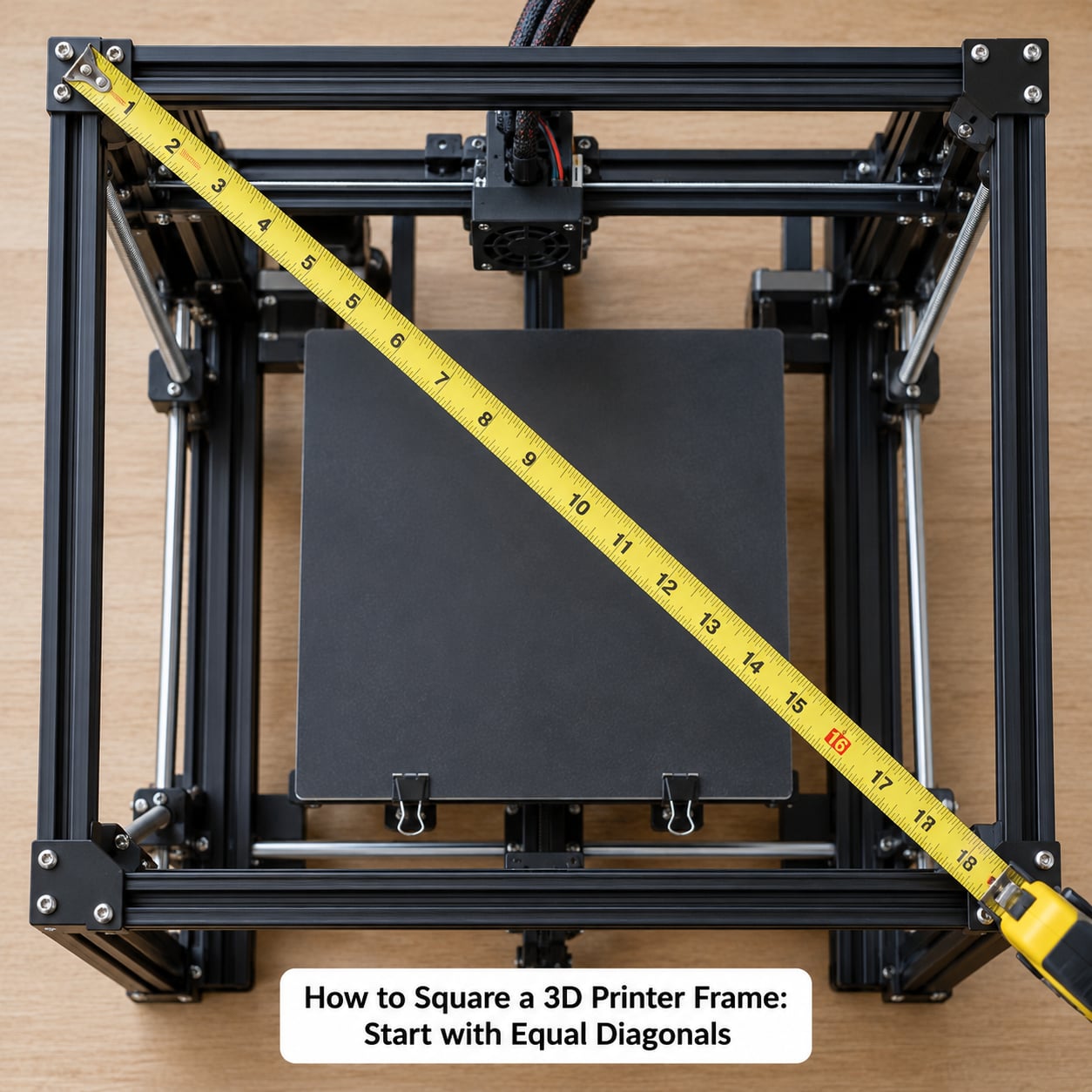
Put the frame on a flat, solid surface. Measure diagonal A from the outside of one vertical rail to the outside of the opposite vertical rail, low on the frame, and then measure diagonal B across the other pair of corners. Write both numbers down.
For a square, diagonal A and diagonal B are identical. If A is longer than B by some amount, the frame is a rhombus: one pair of sides is stretched and the other pair pulled in. The long diagonal points at the two corners that have moved apart, so those are the corners you will nudge back toward each other.
Measure the frame’s width and height too, on all four sides rather than two. This separates two different faults. If opposing sides measure equal but the diagonals differ, you have twist. If opposing sides already differ, the frame is not a rectangle yet and you fix that first, in the next step.
Do not chase small numbers. A 0.2 mm difference across a 400 mm diagonal on an extrusion frame is within what the hardware can hold, and tightening pressure alone will create or destroy that much. Note it, and treat anything under about 0.5 mm on a manual-level machine as finished.
Loosen the Joints Without Removing the Frame
You only need enough movement to shift a corner by the error you measured, which is usually under a millimetre. Back the frame fasteners off roughly half a turn and no further. Lulzbot documents exactly this in its assembly instructions, where the order is the top bolts first, then the lower Z bolts on each side, half a turn on each.
Work in a pattern rather than corner by corner, so the frame does not hang off one loose joint. Support the structure with one hand while you turn the driver with the other, because loose extrusion frames are springy and can drop a corner out of position.
Watch what is attached. Belts, cable chains, limit switch wiring, the Z lead screw coupler, and bed harness all put tension on the frame. If a joint will not move, a cable is pulling on it, and unplugging or slackening that cable is part of the job, not an interruption to it.
Do not loosen T-nut hardware. Advice to back off T-nuts circulates widely and it is wrong. A loose T-nut adds play, it does not correct an angle, and it makes the next gantry alignment worse. If a printed corner bracket is the thing that will not hold an angle, that is a different repair.
Equalize the Frame Width and Height
With the joints loose, bring opposing sides to the same dimension. Work one axis at a time and use the smallest increments you can manage, which on printed brackets often means moving a fastener a fraction of a turn and re-seating it.
Hold a machinist’s square in each corner in turn and check that the two rails meet at 90 degrees. Do not assume equal diagonals means square corners, because a rhombus has equal angles and unequal diagonals, and you can have both problems at once. The square catches angular error that the tape measure cannot see.
If a corner will not come to 90 degrees no matter how you set it, stop adjusting and check the parts. Look at the corner bracket against a straightedge, and check the end faces of the extrusion with the flashlight for damage. Bent brackets from shipping and assembly are a common hidden cause, and forcing a bent bracket square is how people crack a printed part.
Correct the Remaining Diagonal Difference
Re-measure both diagonals after each change. Nudge the corner that the long diagonal points at, by a small amount, then measure again. Two or three iterations of a millimetre or less will usually close the gap.
Use a shim or a washer under a fastener head for sub-millimetre correction. That is far more controllable than trying to turn a bolt by an amount your fingers cannot judge, and it is reversible if you overshoot.
Stop at the tolerance your printer can hold, not at zero. On a manual-level machine, a diagonal difference under about 0.5 mm is where further adjustment stops paying. On a machine with a probe or sensor for bed levelling, the gantry tolerance is far tighter, around 0.1 mm, because a sensor reading taken from a gantry that is out of level is a reading of the error.
Tighten and Recheck the Frame
Tighten in a cross pattern, working opposite corners in rotation, and snug each fastener before moving on to the next. A small torque driver set to a low value is genuinely better here than feel, because it keeps every bolt at the same load.
Do not over-torque. Printed brackets deform, and once a plastic corner deforms you have changed its angle in a way no measurement will forgive. Lulzbot’s assembly documentation explicitly warns that its lower Z bolts will break if tightened harder. If a fastener bottoms out in soft plastic, stop.
Re-measure the diagonals after each group of hardware is secured, not just at the end. Most of the squareness you achieved in the loose state is lost the moment the first tight bolt pulls its corner in, and that loss is exactly what the re-check catches.
Mistakes to Avoid While Adjusting
- Measuring between the wrong points. Mixing inside-edge and outside-edge references produces a phantom error that never goes away.
- Adjusting only one diagonal. Move a corner, then check both. Always both.
- Tightening before the geometry is right. Once the bolts are loaded you are fighting the frame instead of the measurement.
- Trusting an uncalibrated square. Check it against a known straight edge. Cheap squares do warp.
- Forcing fasteners into mismatched holes. A hole that will not line up is telling you the parts are bent or offset. Follow the signal instead of leaning on the driver.
- Ignoring what is attached. Cables, belts, feet, bed mounts and the lead screw all resist a geometry change you have not accounted for.
- Hammering a bracket straight before checking the frame. If the frame is out of square, straightening the bracket just moves the error somewhere less visible.
Verify the Repair Before Printing
Reconnect cables, refit the gantry and the Z assembly, and support the gantry while you lower it, because a free gantry can drop onto the rods and bend something. Then check for binding with the motors disabled by turning the shafts or couplers by hand through the full travel.
Move each axis slowly and listen. A grind, a notch, or a step in the rotation is a mechanical fault, and printing through it will damage rods and belts.
Squaring the frame changes the position of everything mounted to it, so the calibration you did before is now suspect. Re-run it in this order:
- Bed leveling, or the mesh sensor pass, from scratch.
- Z-offset.
- Belt tension, since a shifted belt changes effective tension.
- XYZ calibration where the machine supports it.
- A first-layer test and a 20 mm calibration cube, measured with calipers at all four corners.
Run the first print cautiously, a short low-profile part rather than a tall one, and check all four corners. If the cube measures within a consistent amount on all four sides, the frame is holding square.
Common Mistakes and How to Correct Them
Symptoms are useful here, because a misaligned frame announces itself in the print before it announces itself in a measurement. This table assumes you have already confirmed the frame reads out of square on the diagonals.
| What you see | Likely cause | Fix |
|---|---|---|
| Squares print as rhombuses or diamonds | Frame twist, diagonals unequal | Diagonal method, nudge the corner the long diagonal points at, retighten in a cross pattern |
| Circles and holes print as ovals | X and Y axes skewed, often a misaligned gantry | Check gantry-to-frame gap with calipers, then the rods against a straightedge |
| One corner of a tall part lifts or warps | Bed not parallel to the XY plane after a frame change | Re-level or re-mesh, re-check Z-offset, verify the bed is supported at all four corners |
| Sensor or probe readings swing wildly | Gantry out of level to the frame, even 0.1 mm | Measure the gap at all four corners, correct the high side, reset the probe offset |
| XYZ calibration fails or will not save | Rods skewed, motor shafts not centred in couplers | Re-seat rods so shafts sit centred, re-run the calibration routine |
| Diagonal banding or noise on one axis | Binding, a partially seated rod, or a bent bracket | Turn the axis by hand through full travel and locate the notch, then address the joint |
| Alignment will not hold after tightening | Over-torqued printed bracket, or a bent extrusion end | Back off, replace or shim the bracket, check the extrusion end face for damage |
Aluminum extrusion frames and welded or rigid frames need different expectations. Extrusion is a bolted structure that can flex under load and drifts with temperature, so you tighten it, verify, and check again after a few months of printing. A welded steel or rigid cast frame barely moves, which means if it is out of square, the correction is shimming or replacing a part rather than adjusting fasteners.
If your printer’s manual states a squareness tolerance, that number wins over anything here. Some machines are designed with a small intentional offset. Prusa forum user thrawn86 made the point well: the three-bearing axis layout is designed to tolerate some slop deliberately, so effort spent chasing perfection there can cost hours and change nothing you can measure in a print.
Frequently Asked Questions
How much diagonal difference is acceptable on a 3D printer frame?
On a manual-level machine, a diagonal difference under about 0.5 mm across the frame is where adjustment stops paying. Machines using a probe or sensor for bed levelling need far less: roughly 0.1 mm, because the sensor reads the gantry angle as error. If your printer’s manual states a tolerance, that figure takes priority over any general guidance.
Do I have to loosen the whole frame to square it?
No. Back off the corner and rail fasteners about half a turn and work in a pattern, which is how the Lulzbot assembly documentation describes the process. You need enough free movement to shift a corner by the amount you measured, which is usually under a millimetre. Do not remove joints entirely, and do not loosen T-nut hardware; that adds play without fixing the angle.
Why do my diagonals still differ after I check with a machinist’s square?
Usually because a corner is out of 90 degrees while the overall shape is close to a rhombus, so the square reads fine but the diagonals disagree. A bent corner bracket or a damaged extrusion end face does the same thing. Hold each corner against the square, then check the bracket and extrusion ends with a straightedge and a flashlight before adjusting further.
Should I square the frame or the gantry?
Measure both and let the numbers decide. Frame squareness is the corner-to-corner diagonal difference. Gantry alignment is the gap between the gantry and the frame, measured at all four corners with calipers. If the diagonals are even but the gantry gap varies, fix the gantry hardware, not the frame. Plenty of searches for frame squaring are actually gantry problems.
How do I know if my frame is warped beyond a simple fix?
If a corner will not hold 90 degrees with the fasteners properly tightened, and the bracket is straight and the extrusion ends are clean, the frame itself is deformed. At that point shimming the joint or replacing a bracket is the realistic repair, and a warped extrusion usually means the part is replaced rather than adjusted. Test print a tall thin part first to confirm the error is real and not a belt problem.
Do I need to recalibrate after squaring the frame?
Yes, treat it as mandatory rather than optional. Moving the frame changes the bed height, the gantry angle, and belt geometry, so your old settings are measuring the wrong thing. Re-level or re-mesh the bed, reset Z-offset, re-check belt tension, re-run XYZ calibration where the machine supports it, then print a 20 mm cube and measure all four corners before anything else.
Conclusion
Start by measuring both diagonals and writing the numbers down. That single reading tells you whether you have twist, a broken rectangle, or a problem that is not the frame at all, and it gives you a before and after value that is worth more than any opinion about how it looks.
Then work in small, controlled steps: loosen about half a turn, support the frame, move a corner slightly, re-measure, and only tighten once the frame reads square. When it resists, stop and look for a bent bracket or damaged extrusion end before adding more force.
If a corner will not hold an angle no matter what you adjust, or the printer’s own manual specifies tolerances your measurements cannot meet, take it to the manufacturer or a qualified repair professional rather than continuing to tighten hardware that is already deformed.