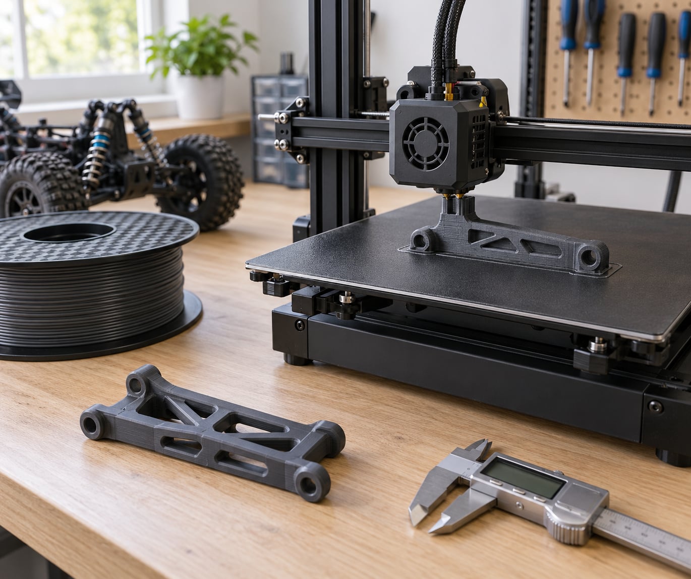
Most 3D printed RC car parts do not fail because the filament was weak. They fail because the load crosses a layer boundary, the walls were too thin, or the part was oriented so that a crash pulled straight through the layer lines. Learn how to 3D print RC car parts that last and the answer is short: match the material to the job, turn the part so bending forces run through the perimeters, and print with three or four walls at a sensible layer height. Get those three things right and an ordinary hobby printer makes parts that survive a season of hard driving.
That said, some parts are simply not worth printing. A rear spindle or a main drive gear takes loads a plastic layer line cannot carry, and forum experience is blunt about that: printed parts will not match injection-moulded nylon no matter how good the settings get. The rest of this guide is about the parts that work well, and how to push them further than a default profile does.
Expect about 20 minutes of measuring and planning per part, then print time that ranges from 45 minutes for a shock tower brace to several hours for a full chassis or body. Difficulty sits at beginner level for PETG and step up once nylon enters the picture.
Table of Contents
- 1What You Need
- 2Step-by-Step
- 3How to 3D Print RC Car Parts That Last: the four decisions that matter
- 4Measure the Part and Plan the Print
- 5Choose an Impact-Resistant Material
- 6Set Layer Height, Walls, and Infill
- 7Orient the Part for the Load
- 8Print, Cool, and Check the Part
- 9Reinforce and Finish the Part
- 10Common Mistakes
- 11Tips
- 12Frequently Asked Questions
- 13What material is best for 3D printing RC car parts that need to withstand crashes?
- 14Does higher infill make an RC car part stronger?
- 15Is PETG strong enough for RC suspension parts?
- 16Should I print RC car parts in solid PLA?
- 17How do I stop printed RC parts from snapping at the layer lines?
- 18Conclusion
What You Need
You need more than a printer and a spool. A durable part comes from having the right things on the bench before the first layer goes down.
- A printer that holds temperature. An enclosed printer with a heated chamber, or at minimum a door and shroud you close for the whole print. Nylon, ABS and ASA will not stick to a cold, open bed.
- Impact-resistant filament. PETG for general work, nylon or carbon-fiber nylon for load-bearing parts, TPU at 95A or firmer for anything meant to flex or absorb vibration.
- A hardened nozzle if you run composites. Brass wears out fast on carbon fiber and glass fiber. Pair abrasive filament with a hardened steel or ruby nozzle and change it on a schedule rather than when it finally fails.
- A filament dryer if you print nylon, PETG or TPU. All three absorb moisture from the air, and wet filament prints with weak, chalky layer adhesion that looks exactly like a temperature problem.
- Digital calipers for measuring the original part and checking hole spacing. This is the single cheapest tool in the workflow and the one that prevents the most wasted prints.
- Model files you trust. Download the STL, then check it in your slicer for thin walls, floating islands and missing screw bosses before committing print hours to it.
- Post-processing supplies: flush cutters, sanding paper or files, a primer that will bond to plastic, epoxy or a tough CA adhesive, and heat-set threaded inserts for repeated bolt threads.
- Safety basics: an enclosure or fume extraction when printing ABS, ASA, polycarbonate or nylon, and nitrile gloves for handling uncured abrasive filament and sanding dust.
Check clearances and fit before the first print, not after. Measure the original part, and print one small test piece at your intended settings. Ten minutes on a coupon tells you whether the material adheres before you spend an evening on a full chassis.
Step-by-Step
How to 3D Print RC Car Parts That Last: the four decisions that matter
Durability comes down to four choices, and only one of them is the filament brand. First, material: pick something with real impact resistance rather than raw stiffness, because RC parts get hit. Second, orientation: rotate the part so bending loads travel through the perimeters, not across the layer lines. Third, walls and layer height: three or four perimeters at a layer height no taller than a quarter of the smallest wall. Fourth, reinforcement at the specific spots that take the hit.
Change any one of those and you get a different part. Change all four and you get a part that survives the crash where the old one let go. Everything below is detail on how to make each decision.
Measure the Part and Plan the Print
Measure before you model. Take the original part off the car if you can, and record mounting hole spacing, shaft diameters, bearing seat sizes, body contours and every clearance where the part rotates or slides past something else.
Then look for the stress locations. On a suspension arm that is the hinge pin area and the point where the arm meets the shock tower. On a chassis plate it is the motor mount, the shock tower base and the center diff mount. On a battery tray it is the strap anchor. These are the spots that will need more material, an extra gusset, or a printed-in insert.
Decide next whether to copy, scale or redesign. Scaling changes hole sizes and wall thicknesses, so a scaled model often needs its holes re-sized. Redesigning is worth it for grip features, cable routing and lightening holes that a moulded part does not need. If you are modelling yourself, add fillets at every internal corner; a sharp internal corner is a crack waiting to start.
You can tell the plan worked if your printed test piece drops onto a hard floor from about a metre without cracking or delaminating at the layer lines.
Choose an Impact-Resistant Material
For load-bearing parts, nylon and carbon-fiber nylon have the highest flexural strength of the common FDM filaments. For everything else, PETG is the sensible general answer because it is tough, easy to print and far more forgiving than nylon. Here is how the usual options compare for RC work.
- PLA — stiff, accurate and cheap, but brittle and low in heat resistance. It cracks rather than deforms, which makes it a poor choice for anything that takes an impact or sits in a hot car. Fine for light interior trim and mock-ups.
- PETG — the default for most printed RC parts. Good impact resistance, layer bonds that hold up, no enclosure needed on most printers, and it sands and paints reasonably. Slightly stringy, which matters on tight-fit parts.
- ABS and ASA — tougher and more heat resistant than PETG, with better chemical resistance. They need an enclosure and they warp if the chamber is not warm. ASA also holds up far better to UV, so it is the better pick for parts that live outside on a rock crawler.
- Polycarbonate — the strongest common filament for impact, with a high heat deflection temperature. Difficult: high temperatures, warping, and it bonds to itself so well that supports are a genuine fight. Worth it for a small number of critical parts.
- Nylon — exceptional toughness and abrasion resistance, and the standard answer for high-load parts. It absorbs moisture quickly, so dry it before every print and print inside an enclosure. Poor bed adhesion until the bed is primed.
- Carbon-fiber nylon (PA-CF) — stiffer and more dimensionally stable than plain nylon, with much better heat resistance. Abrasive to nozzles, expensive, and it will not print on an unprimed smooth glass bed. This is the top-end choice for chassis and suspension parts.
- TPU — flexible and nearly unbreakable, so it absorbs vibration and impact instead of transmitting it. It is a poor choice for rigid load paths and a good one for bumpers, diff guards and anything meant to flex.
Map the material to the part rather than picking one filament for the whole build. Rigid chassis and suspension in nylon or PA-CF, bumpers and guards in TPU, body panels and battery trays in PETG or ABS, and anything structural that lives in the sun in ASA.
Set Layer Height, Walls, and Infill
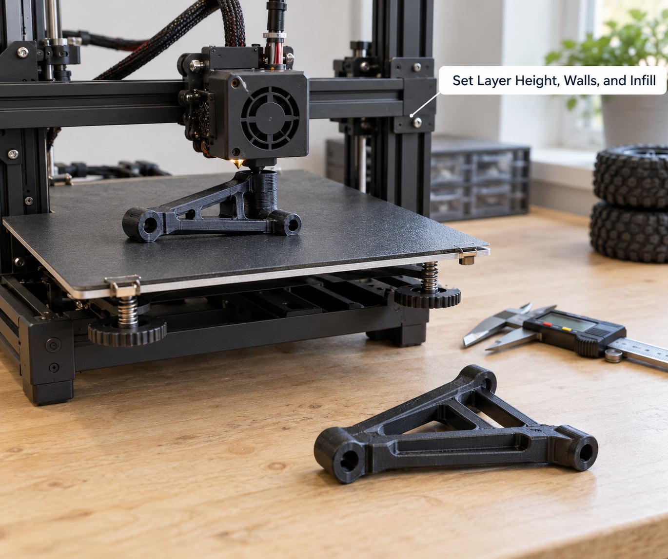
Wall count matters more than infill. Most slicers let you add walls quickly, and each extra perimeter raises strength far faster than another 20% of infill does. Four walls is the practical default for functional RC parts. Three works for lighter parts, and two is about the minimum you should accept on anything that gets hit.
Keep the layer height at or below a quarter of your thinnest wall. A 1.2mm wall printed at 0.3mm layers works. The same wall at 0.4mm layers is a single extruded bead wide in places, and that bead becomes the crack line. On small RC parts, 0.12mm to 0.2mm layers give the best combination of strength and print time.
For the nozzle, a wider nozzle prints a small functional part faster with no real loss of strength. Many hobbyists run 0.8mm to 1.0mm nozzles for brackets and arms because the thicker extrusion lines bond to each other well. A 0.4mm nozzle is worth it when the part has fine features, small screw holes or a tight fit against another component.
Infill comes after walls. Forty percent gyroid is a good all-rounder because it resists load from several directions at once. Concentric infill is the pick for parts that flex, since it bends smoothly instead of cracking. Solid infill is fine and often sensible for small parts like shock tower braces and battery straps under about 30mm, where the part is mostly wall anyway. Raise top and bottom layer counts, because those surfaces take shock loads too.
You will know the settings are right when the part weighs what you expected, the perimeters look continuous around the outside, and a corner test break shows a rough, fibrous break rather than a clean split.
Orient the Part for the Load
This is the step that saves the most parts. FDM prints are far stronger within a layer than between layers, so the direction of the load matters enormously. A suspension arm printed flat will usually crack across its width in a single side impact. Rotate the same arm so its length runs along the X or Y axis, and that same impact now has to tear through solid perimeter lines.
Rotate parts so the main bending axis lies along the print bed, keep curved bumpers vertical so the curve is a continuous wall, and print gear carriers upright so the teeth are full-height extrusion rather than short stubs. Where a part genuinely cannot avoid crossing layers, overlap the geometry and add a gusset at that corner instead of trying to squeeze the print in.
Orientation changes tolerances, so budget time to re-check fit after printing. A part that needed rotating usually needs a hair more clearance, and a sloped surface on a layer line is wider than the same surface printed flat.
Print, Cool, and Check the Part
Adhesion to the bed and adhesion between layers are separate problems, and fixing the first does not fix the second. Use a brim on large flat parts, clean the bed, and check the first layer at full width before walking away. A slightly squashed first layer is worth the five seconds.
For the layers themselves, print hot enough for good bonding and slow enough for the nozzle to lay down consistent beads. Overlapping extrusion width and a light external seam help. Resist the urge to blast the part with a fan; heavy cooling on hot materials raises layer adhesion problems rather than fixing them. A part printed with cooling at 100% in PETG and the same part printed with a light or disabled fan can feel like two different materials.
Check the finished part before fitting it. Look for delamination at the layer lines, gaps or pinholes in the perimeters, visible infill voids inside thin sections, stringing at bolt holes, and any corner that lifted or cracked during cooling. Flex it gently by hand first; a part that creaks before it breaks has a defect worth reprinting.
Reinforce and Finish the Part
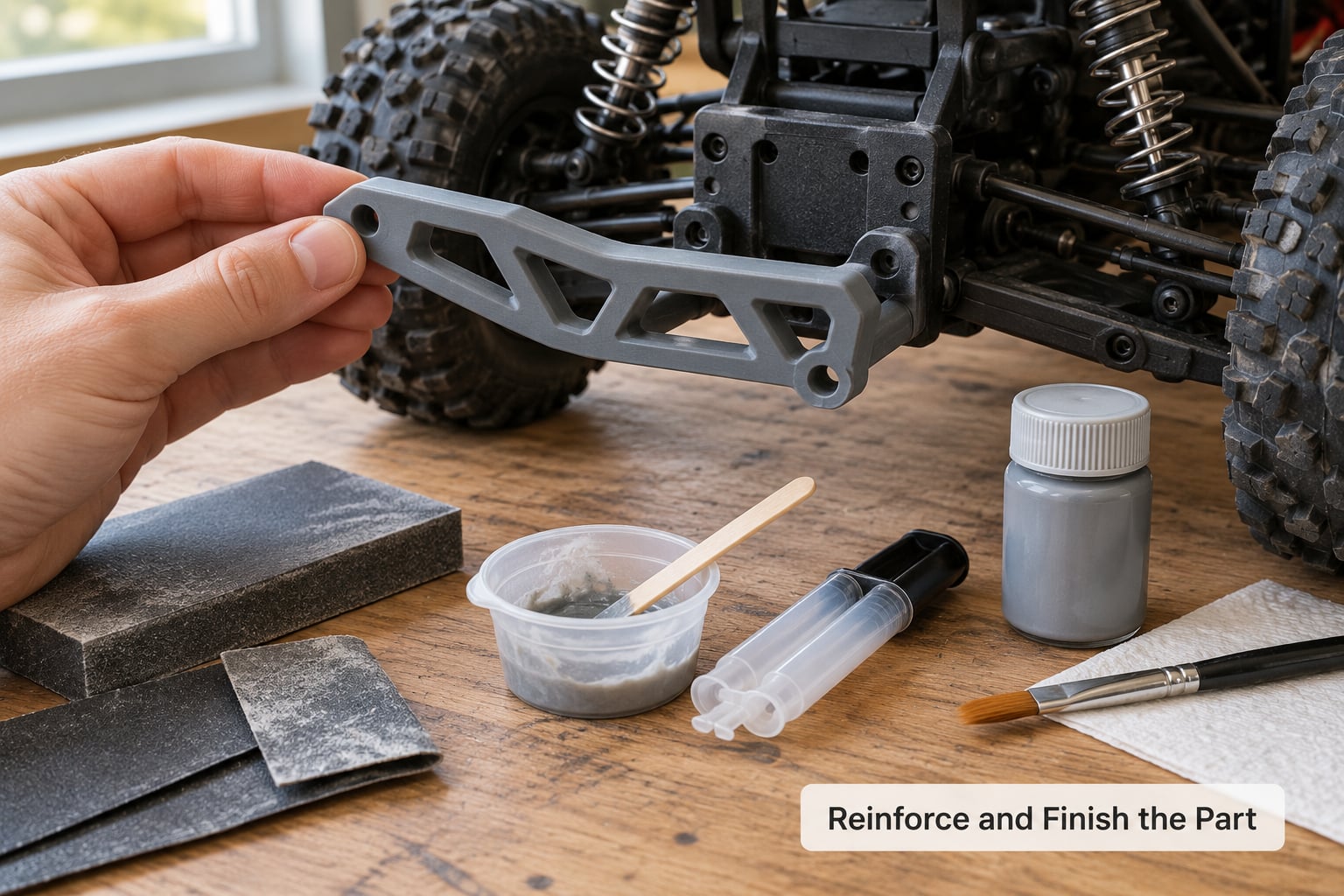
Remove supports while the part is still slightly warm and take light passes instead of trying to lever a big island off cold. If a support scar remains, flush it back and fill with epoxy or filler rather than leaving a notch at a stress point.
Fit the part to the car before finishing it. Confirm the bolt holes line up, hinge pins move freely, and nothing rubs under full steering lock or full compression. A part that needs forcing into place will crack on the track, not the bench.
Then reinforce where the load actually goes. Thin epoxy or a tough cyanoacrylate at a hinge pin boss, a printed-in rib across a flat plate, or a small gusset where a bracket meets its mount all add real strength. Hobbyists often use a low percentage of infill with gloop or epoxy reinforcement to keep weight down on body panels and covers, and the same trick works on a lightened shock tower. For repeated bolt threads, press a heat-set insert into the printed boss rather than threading plastic over and over.
For finish, sand through a few grits, wipe with a solvent, and use a plastic-adhesion primer. Printed plastic will not hold paint reliably without one, and paint on a raw FDM surface peels in sheets after the first crash. Skip annealing unless you know the material and the result you want; it can distort a part that relies on a tight tolerance.
Common Mistakes
Almost every broken printed RC part comes down to one of a short list of fixable problems.
- Splitting along the layer lines. The impact loads ran across the layers. Rotate the part so the load follows the perimeters, and add a gusset at the failure corner.
- Too few walls. Two-wall parts have almost no section to resist a side impact. Go to four perimeters before you raise infill.
- Layer adhesion failures. The material was wet, the fan was too strong, or the temperature was too low. Dry the filament, drop the fan, and add a few degrees.
- Cracking in the infill rather than the walls. A light, sparse infill cannot carry the load. Raise density, switch to gyroid, or go solid for small parts.
- Heat softening in a parked car. Interior temperatures climb fast. Move that part to ASA or polycarbonate, or accept it as a short-life item.
- Unsupported stress points. An unsupported sharp corner concentrates stress in a few millimetres of plastic. Add a fillet, a rib, or a support block that becomes part of the part.
- Clearance too tight. A part that binds under load carries that load straight into itself. Leave a little more room, then check it at full travel.
- Crushed threads in plastic. Bolt torque is shearing the boss apart. Use a heat-set insert or a longer boss with more surrounding material.
Tips
A few habits make a printed parts collection last much longer.
- Keep spares of anything that breaks. A spare wishbone printed while the good one is still intact turns a lost race into a pit stop.
- Write your settings into the model file name or a note on the bench. Six months later you will not remember whether that arm was 4 walls at 40% gyroid or 3 walls at 60% grid.
- Design for replaceability. A cheap sacrificial servo saver or bumper that is meant to break protects the expensive shock tower behind it.
- Inspect parts after hard impacts. A part that flexed and whitened, or that clicks where it used to turn freely, is developing a crack.
- Watch the gram count. Dense filament at 60% infill adds weight to the one place on the car where weight costs lap time. Walls first, light infill, reinforcement only where the load demands it.
- Build a small coupon in the same material before each new filament. Two minutes of setup saves a failed evening of printing.
Frequently Asked Questions
What material is best for 3D printing RC car parts that need to withstand crashes?
Nylon and carbon-fiber nylon are the strongest common choices for load-bearing RC parts such as chassis plates and suspension arms. PETG is the best all-round option and handles crashes well on an open printer. TPU at 95A or firmer absorbs impact without cracking, which suits bumpers and guards. PLA is stiff but brittle and is the first choice to avoid on anything that gets hit.
Does higher infill make an RC car part stronger?
Only a little, and only up to a point. Infill sits inside the perimeters, so once you have three or four solid walls most of the strength is already there. Raising infill from 40% to 60% adds a few grams and a little stiffness. If a part keeps cracking, add a wall or change the infill pattern to gyroid before you add more density.
Is PETG strong enough for RC suspension parts?
For most touring cars, crawlers and general running, yes. PETG prints easily, bonds between layers well and shrugs off ordinary impacts. For a high-speed race car where suspension arms take constant heavy hits, or for drivetrain parts, move up to nylon or carbon-fiber nylon. Printed spindles and drive gears should stay moulded components regardless of material.
Should I print RC car parts in solid PLA?
Generally no. PLA is stiff and accurate but brittle, so it cracks rather than deforms and has low heat resistance for a car parked in the sun. It is still useful for light interior trim, mock-ups and parts that will be replaced often. If you have no other material available, print it with four walls, orient the load along the perimeters, and treat it as a temporary part.
How do I stop printed RC parts from snapping at the layer lines?
Turn the part so bending and impact loads run along the perimeters rather than across them, which is the single biggest fix. Add a fourth wall, keep the layer height under a quarter of the thinnest wall, and print with less fan cooling so the layers bond properly. A gusset or epoxy reinforcement at the exact point of the break stops the failure permanently.
Conclusion
Start by printing a small coupon in your intended material with four walls, a sensible layer height and 40% gyroid, then drop it on a hard floor. That ten-minute test tells you more than a full evening of failed chassis prints.
The strongest part comes from matching material, orientation, wall count and reinforcement to the specific load the part carries, not from any single filament name. Match those four things and your 3D printed RC car parts will hold together through the crashes that used to end your run.