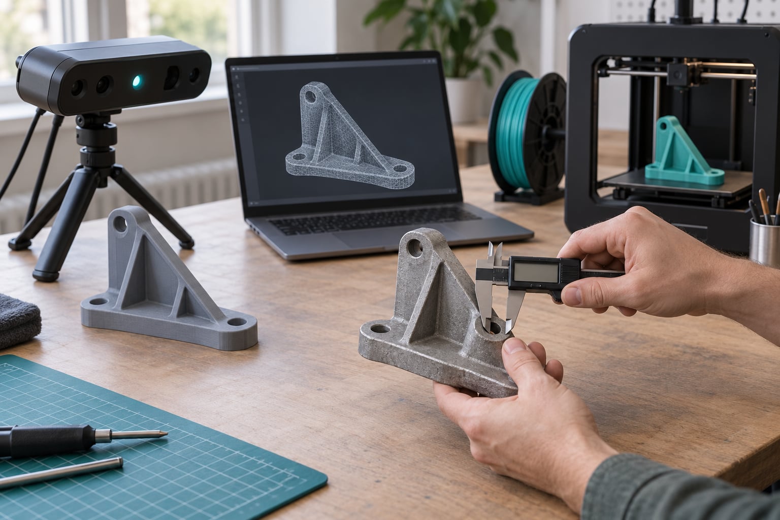
Reverse engineering a part for 3D printing means measuring or scanning an existing physical part, then rebuilding its geometry as an editable CAD model so you can print a working replacement. Most of the effort goes into turning a capture of worn, damaged real-world geometry into clean design intent, not into the printing itself. Budget a few hours for a simple plastic clip and a full weekend for anything with mounting holes or moving interfaces.
The order below is the order that saves time. Decide what accuracy the fit needs, capture the shape, clean it up, rebuild it parametrically, adjust for the printer, then print a cheap test before committing to the real one.
Table of Contents
- 1What You Need
- 2Step-by-Step: How to Reverse Engineer a Part for 3D Printing
- 31. Define the Part’s Function and Printing Requirements
- 42. Measure or Scan the Existing Part
- 53. Create a Reference Mesh in CAD Software
- 64. Rebuild the Geometry and Recreate Features
- 75. Make the Model Printable
- 86. Print a Test and Verify the Fit
- 9Common Mistakes
- 10Frequently Asked Questions
- 11How is reverse engineering used in 3D printing?
- 12Is it illegal to reverse engineer a product and print a spare part?
- 13Which is more accurate, 3D scanning or photogrammetry?
- 14What is the best software for reverse engineering a 3D scan?
- 15Is a mesh model good enough to 3D print?
- 16How accurate does a scan need to be for a replacement part to fit?
- 17Conclusion: Start With Measurement, Then Print a Test
What You Need
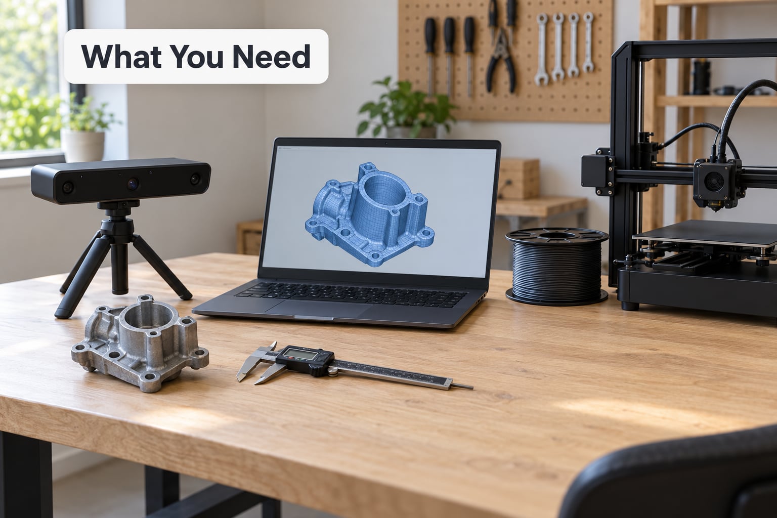
The reference part itself is the only irreplaceable item. Everything else is toolchain.
- The original part, ideally unbroken, or a good sibling part from the same product line.
- Measurement tools: digital calipers for most work, a depth gauge for internal steps and slots, and a micrometer if a bearing seat or shaft diameter is involved.
- Capture options: phone photogrammetry apps like Polycam or Agisoft Metashape, a budget structured-light scanner, or a metrology-grade scanner for tight tolerances.
- Mesh cleanup: CloudCompare or MeshLab, both free, plus Meshmixer for remeshing.
- CAD: Fusion 360 or FreeCAD for parametric rebuilds; Geomagic Design X or VXmodel if you want automatic surface-to-CAD fitting.
- Slicing: PrusaSlicer, Cura or Bambu Studio, plus your printer’s own calibration data.
- Safety gear: eye protection and nitrile gloves if the part came off a machine, and a respirator plus extraction if you print resin indoors.
Which capture method you pick depends on how much accuracy the fit demands and how much of the part you can already see. Photogrammetry is faster but needs texture; structured light struggles with shiny plastic unless you spray it matte.
| Capture method | Typical accuracy | Setup time | Best for |
|---|---|---|---|
| Digital calipers | About 0.02 to 0.05 mm on a good caliper | Minutes | Mating dimensions, holes, thickness, simple brackets |
| Phone photogrammetry | Roughly 0.2 to 0.5 mm on a textured surface | 20 to 40 minutes of photos | Large shells, housings, covers, sculptural forms |
| Budget structured-light scanner | Roughly 0.05 to 0.1 mm | Under 5 minutes | General mechanical parts, brackets, small mechanisms |
| Professional metrology scan | 0.02 mm or better | Half a day including alignment | Precision interfaces where clearance matters |
Scan or photogrammetry gives you the shape. Calipers give you the dimensions that actually have to be right. Serious hobby workflows use both, taking every mating dimension by hand because a scan tends to be slightly off on a surface that is worn or slightly out of parallel.
Step-by-Step: How to Reverse Engineer a Part for 3D Printing
1. Define the Part’s Function and Printing Requirements
Start by writing down what the part does, because that tells you what has to be accurate. A housing lid has to fit a gap and nothing else. A bracket that carries a load has to be dimensionally honest to its bolt pattern, or the whole assembly shifts under stress.
Sort the part into one of four buckets:
- Cosmetic or visual — appearance only. Accuracy needs are low and you can add a little clearance everywhere.
- Assembly-critical — snap-fits, slides, latches and covers. Fit matters, but nothing carries serious load.
- Dimensionally critical — bearing seats, shafts, keyed interfaces. Filled or printed hole sizes and slot widths need real measurement.
- Load-bearing or safety-critical — usually a sign to stop and buy an original. See the note in step 5.
You have worked it out when you can name the tolerance for each feature. A typical part that slides on a 4 mm rod wants a 4.2 mm hole, a bracket bolt pattern wants the measured diameter within a tenth of a millimetre, and a purely cosmetic clip can take a full millimetre of slop.
2. Measure or Scan the Existing Part
Photograph the part from several angles first, including one straight-on shot of any face that mates to something else. Those photos become your reference when the CAD rebuild starts.
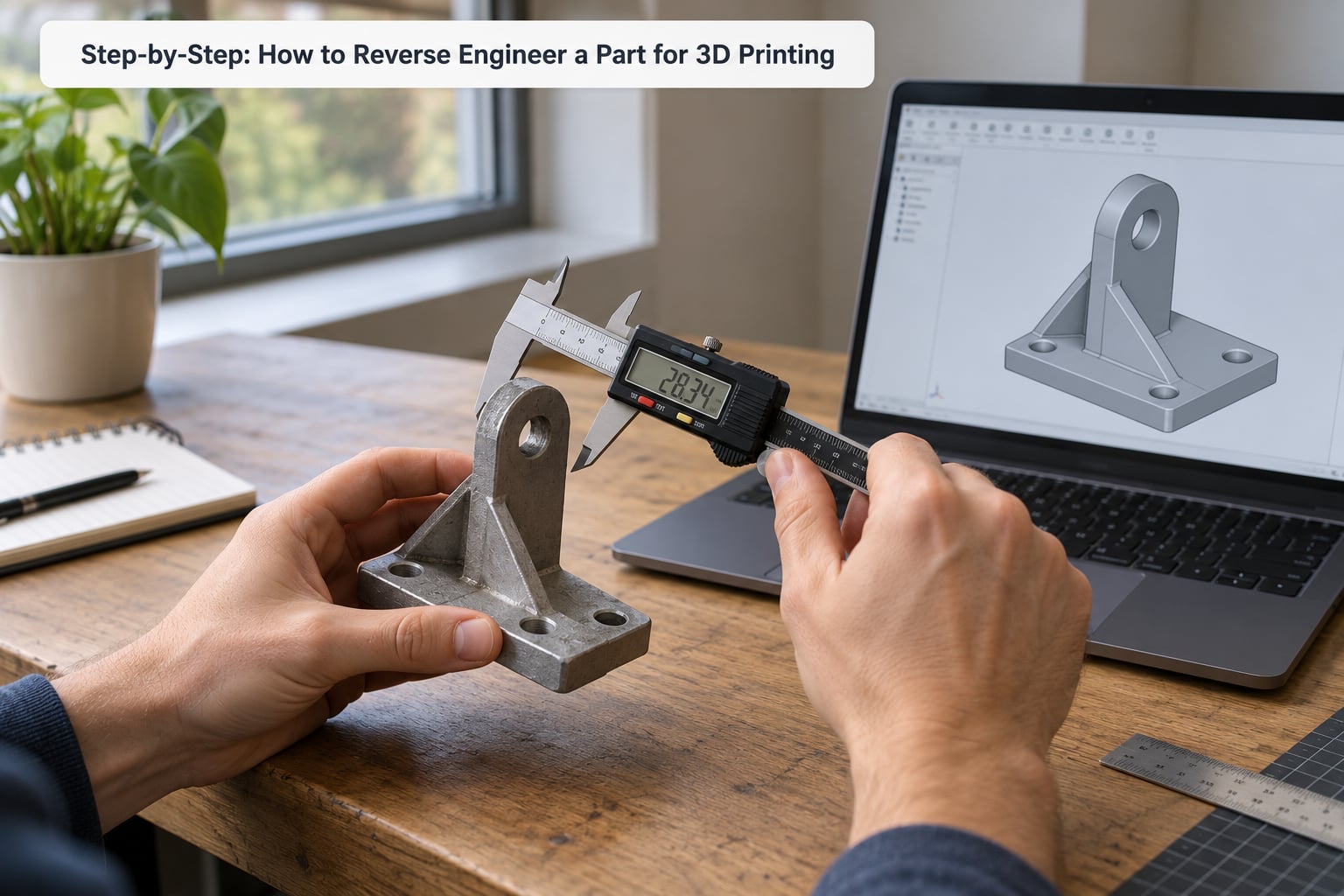
Then measure. Every dimension you take should come off a hard datum, a flat surface or a round feature that is clearly undamaged. Taking a chain measurement from an edge that happens to be chipped gives you a number that looks fine and is wrong by a millimetre. If you have no choice, write the uncertainty down next to the number.
Watch for the design intent behind the numbers. Original parts are usually made to round values: 20 mm, 25 mm, 30 mm, and standard angles like 15, 45 or 60 degrees. If a measured hole comes out at 5.02 mm, the designer almost certainly specified 5 mm. A slot measuring 4.98 mm is a nominal 5 mm feature. Snapping to those values removes measurement noise and makes the model cleaner.
Units give themselves away too. Metric parts show round numbers in multiples of 5 and 10 and thread pitches that feel coarse; imperial parts show fractions, and screws land on familiar quarter-inch multiples.
If the original is damaged, worn or deformed, repair or shim it before scanning. A scan will copy a bent mounting hole perfectly and the reprint will inherit the bend. Where damage is unavoidable, note it and model the as-designed version rather than the as-broken one.
3. Create a Reference Mesh in CAD Software
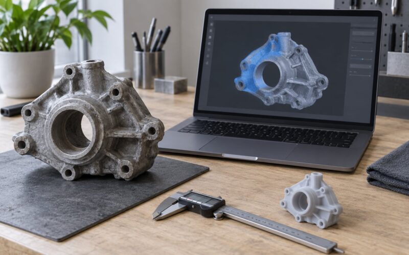
Import the scan as a mesh and treat it as an underlay, not as the model. Importing into CloudCompare first lets you delete stray islands and floaters, align to major axes, and check the scale against a known dimension before you do anything else.
Three checks catch most bad scans. Confirm the bounding box matches a measurement you took by hand, look at the mesh from a direction where the original should be flat to spot a twisted scan, and turn on shading to find smoothed-out areas where the capture lost detail. Shiny plastic and deep narrow slots are where structured light quietly produces garbage.
You have a usable reference when the mesh sits at true scale, sits square to the coordinate planes, and no surface matters to the fit is smoothed away.
4. Rebuild the Geometry and Recreate Features
Rebuild rather than trace. Draw a datum, sketch the primary profile, extrude or revolve it, then add features one at a time. A re-drawn model with real dimensions can be edited later; a wrapped mesh surface can only be scaled, and scaling is what breaks fits.
Work in this order:
- Primary surfaces first — the flat faces and the main body outline.
- Mounting interfaces — holes, bosses, slots and the mating pattern, to your measured numbers.
- Fillets and chamfers, using real radii rather than a smoothed edge.
- Repeated features — threads, knurling, ribs and a pattern of holes, rebuilt from one feature and patterned.
- Cosmetic detail last, and only where it shows.
Threads are a judgment call. Model an internal thread as a plain hole sized to the tap drill, or model a coarse external thread when the fit has to look right but not thread properly. A modelled 3D printed thread is usually weaker than the surrounding wall and rarely worth it.
Stop when the model matches the function. A scan picks up casting texture, draft marks, scratches and a mould parting line that add nothing but print time.
5. Make the Model Printable
The model you drew and the part you get are not the same object. FDM printers undersize holes and lose a little dimension to shrinkage, SLA resin shrinks as it cures, and a first layer squishes outward into an elephant foot. Compensate in the model rather than waiting to see what comes out.
Decide the tolerance band before you start scaling anything.
| Part type | Target tolerance | Printable? | Notes |
|---|---|---|---|
| Cosmetic clip or badge | About 1 mm of slop | Yes | Orientation matters less than anything else |
| Housing or cover | 0.3 to 0.5 mm | Yes | Add clearance at every wall and screw boss |
| Bracket or mounting plate | 0.2 mm on the bolt pattern | Yes | Round out holes slightly; print with the bolt pattern flat |
| Snap-fit latch | 0.2 mm, flexible arm | Yes | Keep the arm thin and print in a tough material |
| Bearing or shaft seat | 0.1 mm or tighter | Sometimes | Print pressed or machined; measure the actual printed bore first |
| Load-bearing structural part | Tighter than FDM gives | No | Buy an original or have it made properly |
There are other adjustments to make while you are in there. Orient the part so the load runs along the layers rather than across them, because layer adhesion is weak in tension and strong in shear. Keep walls at three perimeters or more. Break sharp internal corners with a fillet of at least 1 mm so the nozzle can actually reach inside them. Reduce or remove overhangs, or plan the supports so they land on surfaces you already sand flat. Where a feature needs real strength, add a rib or gusset instead of thickening the whole part.
One caution before you go further. Printed parts are fine for knobs, clips, covers, jigs and brackets. They are not appropriate for anything braking, pressure-retaining, hot, or carrying a person’s weight. Resin prints grind down fast and the resulting dust is genuinely unpleasant to handle. If the part falls into one of those groups, stop here and source an original or a machined equivalent.
6. Print a Test and Verify the Fit
Do not print the whole part first. Slice a small coupon that contains the features you are least sure about — usually one hole, one slot and one wall — and print it in the same orientation and with the same settings you will use for the real part.
Measure the coupon with the same calipers you used on the original. A hole measured 0.2 mm small means you add 0.2 mm to that feature in the model and every other hole of the same size. This single correction step resolves most fit failures, and it costs a few cents.
Then do the physical fit test. Close the lid, push the snap-fit together, slide the part onto its mating rod. Anything that binds gets one adjustment, and one at a time. Two simultaneous changes make it impossible to tell which one fixed it.
Finally, save the CAD file with a clear name, the printer settings you used, and a note of the measured dimensions. A replacement that works is worth more as a file you can reprint in two years than as a plastic part in a drawer.
Common Mistakes
Tracing the mesh instead of rebuilding it. This is the most common failure. A traced mesh carries every bump and wear mark from the original, has no editable dimensions, and cannot be corrected when the fit is off. Rebuild from sketches and primitives, using the mesh only to check your work.
Trusting the scan for mating dimensions. Scan accuracy on a shiny or worn surface is routinely several times worse than the tolerance you need, and the error is invisible unless you check. Measure every critical dimension by hand with calipers.
Copying the damage. Wear, cracks and deformation go straight into the reprint. Repair or shim the original first, or model the as-designed version.
No clearance compensation. A hole modelled at exactly the measured diameter prints undersize on almost every process. Add clearance up front: roughly 0.2 mm for FDM bores, more for snap-fit arms.
Designing the whole part before testing anything. A ten-hour print that does not fit teaches you the same thing a two-minute coupon would have.
Forgetting orientation. A part printed flat that should have been printed on edge will separate along the layers the first time it is loaded. Rotate the part in the slicer until the stress runs along the layers.
A few habits worth keeping. Measure everything twice from two different datum points when the feature matters. Keep the original part in a labelled bag with your new CAD file. And when a scan looks wrong, suspect shiny surfaces before you suspect the software.
Frequently Asked Questions
How is reverse engineering used in 3D printing?
It lets you replace a broken or discontinued part that nobody sells any more. You capture the original with calipers or a 3D scan, rebuild it as a parametric CAD model, then print a replacement. The usual wins are household and appliance plastic parts, discontinued automotive trim, and jigs or fixtures for legacy equipment where no drawings survive.
Is it illegal to reverse engineer a product and print a spare part?
In the US and EU, making a replacement part for something you own is generally fine. Copyright protects the original expression, not the shape or function of a functional part, and patents cover the invention rather than your personal repair. Trademarks are different: printing something that carries someone else’s logo is a problem regardless of who owns the device. Rules vary by country, so check locally if the part is commercial.
Which is more accurate, 3D scanning or photogrammetry?
Structured-light scanning wins on accuracy, typically 0.05 to 0.1 mm, and it captures geometry directly. Photogrammetry works from photographs, so it is fast and cheap but needs a textured, matte surface and settles around 0.2 to 0.5 mm. For shiny injection-moulded plastic, spray the part with matte developer spray first, or the scanner will read the reflections instead of the shape.
What is the best software for reverse engineering a 3D scan?
For parametric rebuilds, Fusion 360 or FreeCAD give you full control and Fusion 360 handles mesh underlays well. For automatic surface-to-CAD fitting, Geomagic Design X and VXmodel trace surfaces and convert them to editable solids, at a higher price. CloudCompare and MeshLab handle the cleanup stage for free. Most hobby workflows combine free cleanup with one parametric CAD package.
Is a mesh model good enough to 3D print?
For appearance and non-critical shapes, yes. Slice the mesh, export an STL and print it. For anything that has to mate with another part, build a parametric model instead. A mesh has no dimensions you can edit, so every fit correction means scaling the whole thing and moving everything else with it. Rebuilding in CAD costs an hour and saves a day of failed prints.
How accurate does a scan need to be for a replacement part to fit?
Match the scan to the fit. Cosmetic clips tolerate a millimetre of error. Covers and housings want 0.3 to 0.5 mm, brackets about 0.2 mm on the bolt pattern, and bearing or shaft seats need 0.1 mm or tighter, which usually means a filled or machined print. If your requirement is tighter than your scanner delivers, measure the critical dimensions with calipers instead.
Conclusion: Start With Measurement, Then Print a Test
Reverse engineering a part for 3D printing works because you separate the shape, which a scan gives you cheaply, from the dimensions, which you have to earn. Know what the part has to do, capture it, rebuild it parametrically rather than tracing it, compensate for the printer, and prove the fit on a coupon before spending hours on the real part.
Start tonight with three things: write down what the part does, take ten caliper measurements off a hard datum, and take photos. That is enough to know whether this is a weekend project or a part you should just order.