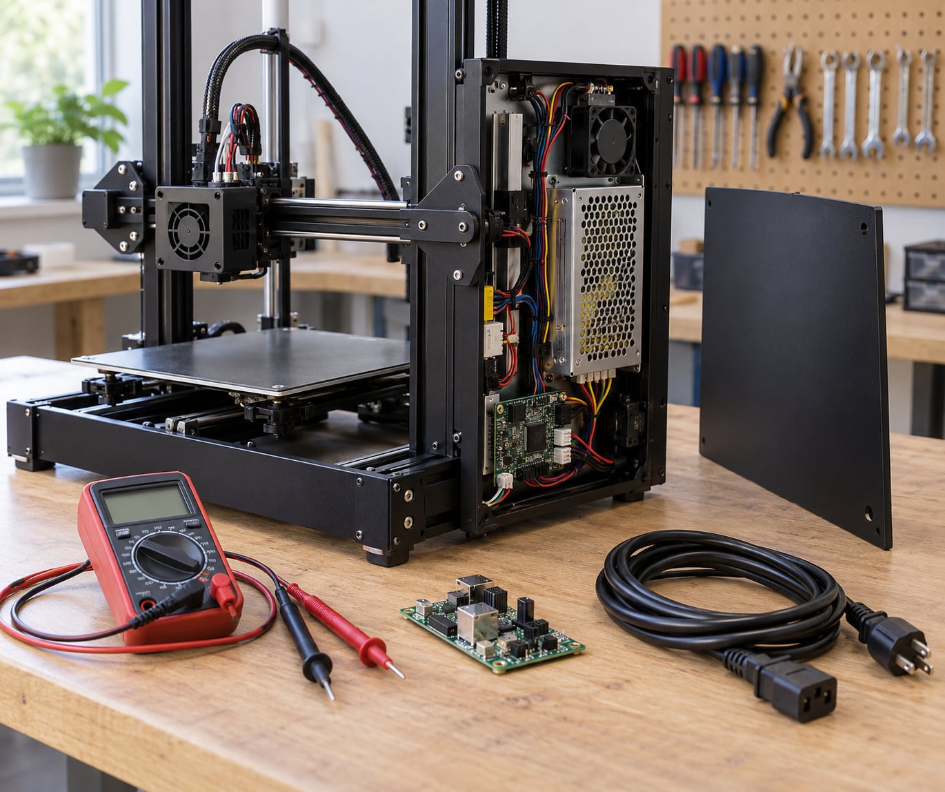
If you are learning how to diagnose 3D printer electrical problems, start at the power source and work toward the component. An electrical fault in a 3D printer is a failure anywhere along the power path: the mains socket and its fuse, the power supply unit, the mainboard, and out to the heaters, sensors, motors, fans and display. You find it by following power from source to load with a multimeter, and the first reading that deviates from the manufacturer spec is the fault.
Most of this takes 20 to 40 minutes for a printer that is completely dead, and longer if you have to get inside the electronics. You need a multimeter with continuity and resistance modes, the printer service manual, and more patience than parts money.
The order matters. Swapping a power supply because it feels like the culprit is the most expensive way to learn nothing, and it is why people end up with three good spare boards and the same dead printer.
Table of Contents
- 1What You Need
- 2Step-by-Step: How to Diagnose 3D Printer Electrical Problems
- 31. Confirm the Power Source and Safety Conditions
- 42. Check Cables, Connectors, and Fuses
- 53. Test the Control Board and Mainboard Connections
- 64. Diagnose Stepper Motors and Their Drivers
- 75. Check Fans, Sensors, and Limit Switches
- 86. Test the Heater, Thermistor, and Bed System
- 97. Isolate the Fault and Decide on the Repair
- 10Common Mistakes
- 11Frequently Asked Questions
- 12Is it safe to probe a live 24V power supply output with a multimeter?
- 13Why is my 3D printer not turning on at all?
- 14How do I know if my mainboard is dead?
- 15Why does my printer beep repeatedly when I turn it on?
- 16What happens if the power goes out while my printer is printing?
- 17Do I need to change firmware settings after replacing a thermistor?
- 18Conclusion
What You Need
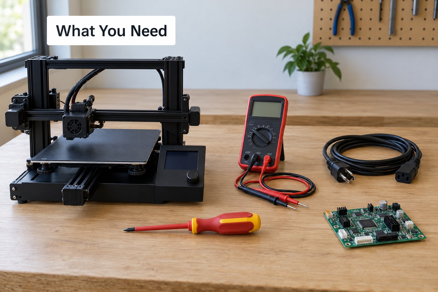
Start with the printer service manual for your exact model and board revision. It carries the expected rail voltages, the thermistor part number, and the fuse rating, and it is the only baseline you can trust.
- A multimeter with DC voltage, resistance (ohms) and continuity modes. A basic one is fine.
- The correct power supply, or at least the specification sheet for the fitted one, so you know the rated output and connector pinout.
- Insulated tools: a Phillips driver, a small flat blade, needle-nose pliers, and plastic spudgers that will not scratch a board.
- Replacement cables and fuses matching the manual: the mains lead, the PSU output harness, and any blade or cartridge fuse the manual references.
- Safety equipment: insulated gloves, an eye protection habit, and an anti-static wrist strap if you will be handling the mainboard.
Two things worth adding if you do this often: a cheap socket tester for the mains outlet, and an infrared thermometer for watching driver and PSU temperatures under load.
Step-by-Step: How to Diagnose 3D Printer Electrical Problems
1. Confirm the Power Source and Safety Conditions
Unplug the printer at the wall and let the hotend and bed cool fully before touching anything. Working on a printer that is still connected to mains is the single most serious mistake in this whole process.
Work down the chain from the wall. Confirm the outlet is live with a socket tester or by checking a known-good device in it. Then read the power supply rating label and compare it with what the printer is supposed to draw.
Inspect the rocker switch on the power supply: many boards have an illuminated switch that only lights when the supply is actually switching the primary side. A dead switch is common on older units and reads as a totally dead printer.
Never open a power supply that is connected to mains. If you need to inspect inside it, it must be fully unplugged and discharged, and honestly most people should stop at the outside of the case.
| Rail | Expected reading | What it means |
|---|---|---|
| Mains input at PSU | Mains voltage within a few percent of local nominal | Pass. Fault is downstream of the PSU if this reads correctly |
| 24V DC main output | 23.5 to 24.5V at the PSU, unloaded | Pass. Below 22V under load means a failing supply |
| 12V DC output (PSU that provides one) | 11.4 to 12.6V | Pass. Fans on 12V die first when this sags |
| 5V rail at mainboard | 4.9 to 5.1V | Pass. Below 4.7V explains blank displays and resets |
| 3.3V logic rail | 3.2 to 3.4V | Pass. Board-level failures often show here first |
| Earth continuity | Near 0 ohms from chassis to earth pin | Pass. Open earth points to two-prong supplies and modified units |
Measure the 24V output at the PSU connector with the mainboard disconnected, then again with it connected. A large difference between those two readings means the mainboard is loading the rail heavily, which usually points at a shorted heater, a shorted driver, or a failed MOSFET.
2. Check Cables, Connectors, and Fuses
With the printer unplugged, reseat every connector you can reach. Ribbon cables on the display and board headers should go in and out with light resistance, not force, and should latch properly if they have a locking tab.
Look for the common physical damage: a terminal screw backed off a quarter turn, a JST or XT connector with a pin pushed back inside, a kinked cable where it passes a moving carriage, or insulation discoloured and brittle near a hotend heater. Heat damage near the hotend is easy to miss because the sheath still looks intact.
Check the fuses next. The mains-side fuse holder on the printer frame, any fuse on the power supply input, and the mainboard’s own input fuse are all worth inspecting visually through the clear housing. A blown blade fuse is the single most common root cause in refurbishment work.
To test a fuse, remove it and set the meter to continuity or low resistance, then probe both ends. A good fuse reads close to 0 ohms. An open fuse reads OL or 1. Never test a fuse while it is still clipped into a circuit, because you will be reading the circuit, not the fuse.
Replace a blown fuse with the same type and rating. A higher rating defeats the protection and lets a shorted heater or driver melt the board.
3. Test the Control Board and Mainboard Connections
Inspect the mainboard with good light. Look for browned or blistered components, a burnt smell, green or white corrosion around the headers, a cracked solder joint, or a trace that has been eaten by a loose screw. Lift the board and look at the underside too; heat damage often shows first there.
Check the header pins for pins that sit lower than their neighbours. A pushed-back pin gives you exactly the symptom of a failed subsystem with no visible damage anywhere else, and it is invisible unless you look sideways at the header in good light.
With power disconnected, continuity checks are allowed on the protective earth path and on obvious cable runs. Measurements on powered rails while the printer runs should follow the manufacturer service manual, because probing the wrong node can damage the board or your meter.
Two techniques close most display faults quickly. Measure the 5V rail at its source on the board, then measure it again at the far end of the ribbon cable feeding the LCD. Good at the source and missing at the far end means the cable or its connector is the fault. Good at both ends and still blank means the display or its contrast setting is at fault.
4. Diagnose Stepper Motors and Their Drivers
Separate the fault into motor, cable, connector, driver or configuration before replacing anything. A motor that buzzes without moving can be any of the five.
Disconnect the motor from the board and set the meter to resistance. Probe between any two of the motor’s four wires, then between the other pairs. Two of the three pairings should read similar values, typically a few ohms for a NEMA 17, and the third pairing should read much higher. That pattern means the windings are intact. An open reading on one winding means a broken coil or a broken lead.
Check the voltage the driver is being asked to deliver. On a board with user-adjustable stepper current, too little current shows up as a motor that is quiet and weak, and too much shows up as a hot driver that shuts down mid-move.
Feel the driver temperature after a few minutes of movement. A driver that is much hotter than its neighbours is pulling abnormal current, which points at the motor, its wiring or a shorted driver output, not at the board’s power supply.
Configuration faults look electrical but are not. Check that the firmware’s steps-per-mm and microstep settings match the mechanics, and that the right TMC or A4988 type is configured for the driver actually fitted.
5. Check Fans, Sensors, and Limit Switches
Most fans take 24V on a hobby printer or 12V on a machine with a 12V accessory rail. Spin them by hand: a fan that feels rough, stalls at one blade position, or rattles loudly has a failed bearing and will drag the rail down.
For thermistors and limit switches, resistance readings are the useful test. A mechanical limit switch should read near 0 ohms when pressed and open when released, and you can confirm which way your particular switch is wired by pressing it on the meter.
Compare every sensor reading against the manual. A hall sensor or optical sensor on a modern board typically reports open or shorted depending on position, and a reading that never changes as you move the axis tells you the wiring, the connector or the sensor has failed.
Before condemning a board, move the carriage by hand. If mechanical resistance feels normal and the sensor reading is dead, the problem is electrical. If the axis binds, you are debugging mechanics with a multimeter, which will not help.
6. Test the Heater, Thermistor, and Bed System
Do not energize a printer whose heater wiring you suspect is damaged. A shorted heater cartridge can take the mainboard’s MOSFET with it, and the second failure is far more expensive than the first.
With everything disconnected, measure the heater cartridge across its two terminals. A healthy 24V cartridge usually reads somewhere in the range of 20 to 100 ohms, and a 12V hotend heater reads higher, often 200 ohms or more. A reading near zero means a shorted cartridge or a shorted wire. An open reading means a broken element or a broken lead.
Measure the thermistor at room temperature. A common EPCOS or Semitec 100k NTC thermistor reads close to 100k ohms at 25 degrees Celsius, and the resistance falls as temperature rises. An open reading points to a broken sensor; a reading near zero points to a shorted sensor, which is the one that takes out a MOSFET when the printer powers up.
| Error code | What the board is reporting | Electrical cause to check |
|---|---|---|
| MINTEMP | Sensor reads below the configured floor | Open thermistor, loose connector, broken wire |
| MAXTEMP | Sensor reads above the configured ceiling | Shorted thermistor or sensor wiring pinched against the hotend |
| THERMAL RUNAWAY | Temperature stopped climbing while power is applied | Failed heater cartridge, blown MOSFET, relay, or loose ground at the heater |
| Heater error | Current sense reading out of range | Shorted heater, failed MOSFET on the driver output |
Distinguishing a blown MOSFET from a bad heater is the classic misdiagnosis. If the heater reads low resistance and the thermistor reads correct, the heater is the fault. If the heater is correct and the board still reports a heater error, the MOSFET driving that output has failed and it will usually read as a short from the output terminal to the negative rail while the printer is unplugged.
On printers using a solid state relay on an external heater board, check the relay’s DC input voltage at the connector while the printer is idle. No voltage at the input means a mainboard or fuse problem; voltage present but no heater output means the relay itself has failed.
Replace a thermistor with the same part number and tell the firmware about it. On Marlin that means the thermistor type and beta value in the configuration file; on Klipper it is the sensor type in printer.cfg. Skipping that step causes a correctly fitted sensor to report wrong temperatures.
7. Isolate the Fault and Decide on the Repair
Use the symptom to pick the first test, then let the readings narrow it further. This table is the shortest route from what you see to where to probe.
| Symptom | Likely subsystem | Test that confirms it |
|---|---|---|
| Completely dead, no lights, no fan | Mains, switch, cable, fuse, PSU | Mains voltage at the PSU input, then 24V at the PSU output |
| LCD blank but fans spin and board LED is lit | 5V rail, ribbon cable, connector, display | 5V at the board source, then at the far end of the ribbon |
| Powers on then shuts off after a second | Shorted MOSFET, shorted heater, undersized PSU | 24V unloaded versus loaded, then heater resistance |
| Resets mid-print, no error shown | Voltage sag, hot enclosure, weak PSU | 24V under load while the bed and hotend heat |
| Motors buzz but do not move | Motor, driver, wiring, stepper current setting | Phase-to-phase resistance, driver temperature |
| Heater will not reach temperature | Thermistor, heater, MOSFET, relay, wiring | Thermistor ohms at room temperature, heater ohms across terminals |
| Repeated loud beep at power-on | Board-level fault, EEPROM, sensor fault | Board LED state, then sensor readings on each axis |
| Trips the house breaker at switch-on | Shorted PSU or shorted internal wiring | Continuity of the mains input wiring with the PSU removed |
Write your findings down before you replace anything: every reading, every connector you reseated, every part you removed. It keeps you from re-testing the same ground twice and makes the next fault on the same printer much faster to trace.
Repair is sensible when the failed part is a discrete, inexpensive item and the board around it is visibly clean: a fuse, a thermistor, a heater cartridge, a cable, a screen, or a power supply. Replacement wins when the damage is on the board itself, when two or more unrelated subsystems are dead at once, or when the printer is at the end of its life and the board is not sold separately.
Stop and take it to a technician when you would have to work inside a power supply, when the fault involves mains voltage beyond the socket and fuse, or when a short appears on the logic rails. There is no shame in that boundary, and boards destroyed by well-meaning probing are a bad trade.
Common Mistakes
Testing equipment that is plugged in. Continuity and resistance modes send a small current through the probe leads, and using them on a live circuit gives you a wrong reading at best. Unplug first, every time.
Replacing the power supply before measuring it. A failing supply usually shows as sag under load, not as a dead output, so a quick unloaded reading can look fine on a bad unit. Measure at the connector, then measure again with the printer connected and the heaters commanded on.
Ignoring the manual’s voltage limits. Probing a node the board does not expect can push mains voltage into a logic rail. If the service manual does not describe the node, leave it alone.
Misreading thermistor resistance. A 100k NTC thermistor does not read 100k in a hot printer. Measure it at room temperature, fully disconnected, and compare against the part number rather than a number you remember.
Bypassing protection circuits. A fuse that keeps blowing is telling you something. Fitting a higher rating or bridging an earth connection turns a small, findable fault into a melted board or a shock risk.
Condemning electronics for enclosure heat. Failures that appear inside a heated chamber and vanish outdoors are usually thermal, not component death. Before buying parts, move the printer to open air and retest.
Frequently Asked Questions
Is it safe to probe a live 24V power supply output with a multimeter?
Yes, with the right meter and the right procedure. Set the meter to DC volts, use leads rated for the voltage and current, and probe only the low-voltage DC output terminals, never the primary side or the mains inlet. Keep the printer’s own power off while probing, never probe while a heater is heating, and stop if the reading is unstable or the meter shows a negative voltage.
Why is my 3D printer not turning on at all?
Work from the wall inward. Confirm the outlet is live, then check the power supply rocker switch, the mains cable, and the mains-side fuse holder. Next measure the 24V DC output at the power supply connector with the mainboard unplugged. No mains input points to the cable, switch or fuse; correct mains input with no DC output points to the power supply itself.
How do I know if my mainboard is dead?
Confirm the power supply first, because a weak unit mimics a dead board. With the board disconnected, verify the power supply still holds 24V. Then measure the 5V rail on the board: if mains and 24V are correct and 5V is absent or far below spec, the board has failed. A board-level short usually also shows as a large difference between unloaded and loaded 24V readings.
Why does my printer beep repeatedly when I turn it on?
A continuous beep on most Marlin-based machines means the board could not read a sensor at startup, most often a limit switch or thermistor. Power off, unplug, and check that the thermistor connector is seated on both the board and the sensor, then check each axis by hand for an endstop reading change. A burnt smell or discoloured connector usually means static damage rather than a wiring fault.
What happens if the power goes out while my printer is printing?
The print is lost, but the hardware is usually unharmless because loss of power disables both heaters. Marlin and Klipper issue a heater error on restart because the sensors read far below the safe minimum, and you clear it with an emergency reset or restart. A stored print can be resumed with firmware that supports it. Add surge protection on the mains side to protect against voltage spikes on return.
Do I need to change firmware settings after replacing a thermistor?
Only if the new sensor is a different type from the one you removed. Fit the same part number where you can and no configuration change is needed. If you move to a different beta value or sensor type, Marlin needs the thermistor type and beta set in the configuration file, and Klipper needs the sensor type set in printer.cfg. A mismatch causes correct hardware to report wrong temperatures.
Conclusion
Start at the power source every time. Unplug before you open anything, let the hotend and bed cool, and work down the chain with a meter until the reading stops matching the manual’s specification, because that first deviation is your fault.
Then replace or repair only the component your measurements actually point to, and stop at the boundary of what the service manual covers. A multimeter turns most 3D printer electrical problems from guesswork into a ten-minute measurement.