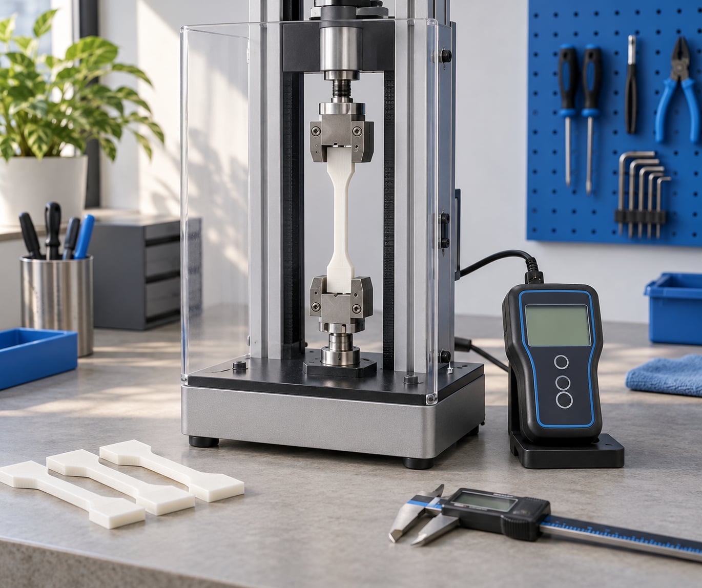
Yes, you can do tensile testing printed parts at home, and the setup is simpler than most people expect: a printed dogbone coupon, something that grips both ends, and a way to measure pulling force as the part stretches and eventually snaps. What a home rig cannot do is certify a material or qualify anything safety-critical. It can compare your prints against each other, which is the number most makers actually need.
The whole job takes about 45 minutes once the equipment is in place. Most of the real work happens earlier: designing a valid specimen, printing a batch of them consistently, and conditioning the filament so moisture does not muddy the results. Get those three right and a modest setup produces numbers you can trust for comparisons. Skip them and you will just generate a number with a unit on it.
Table of Contents
- 1What You Need for Tensile Testing Printed Parts at Home
- 2Step-by-Step
- 31. Define What You Need to Measure
- 42. Design or Select a Valid Test Specimen
- 53. Print and Condition the Coupons Consistently
- 64. Measure the Specimen and Check the Machine
- 75. Mount, Align, and Load the Specimen Safely
- 86. Run Tensile Testing Printed Parts at Home
- 97. Calculate Strength and Check the Result
- 10Common Mistakes
- 11Frequently Asked Questions
- 12Can I perform a tensile test on a finished 3D printed part instead of a test coupon?
- 13How many printed specimens do I need for a reliable home tensile test?
- 14Is a force gauge enough to test 3D printed parts at home?
- 15Which print orientation usually gives the highest tensile strength?
- 16When should I use a professional materials-testing laboratory instead?
What You Need for Tensile Testing Printed Parts at Home
A home tensile test is worth running when your goal is comparison: does orientation X hold more load than orientation Y, did that filament spool arrive dry or wet, did raising wall count from three to four actually matter. It is not worth running when you need a certified material property for a drawing or a compliance file.
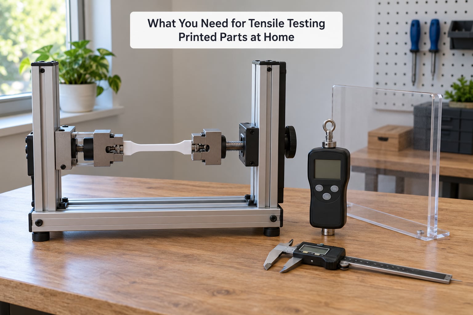
The difference between equipment tiers is real. A universal testing machine is a calibrated, framed instrument with a force sensor in the load chain, a certified measurement system, and grips that do not distort the specimen. A home load frame is a stiff frame with a drive screw and a load cell, which gets you close enough for ranking materials if the frame is rigid and the sensor is calibrated. A cheap hanging scale plus a fishing line rig gets you a rough idea for soft materials and paper, and nothing more.
Here is the working checklist:
- Printed test coupons in dogbone geometry, one per condition you are comparing, plus spares.
- Grips with serrated faces and enough jaw length to hold the wide grip section without crushing it. Wedge grips are the usual home choice.
- A calibrated force measurement device, usually a load cell rated a little above your expected peak load so the reading sits in the middle of its range rather than at the ceiling.
- Displacement measurement for the moving crosshead, plus a way to see strain on the specimen itself.
- Data capture, typically serial logging from a microcontroller to a laptop or SD card, sampling fast enough to catch the peak.
- Thickness and width measurement with calipers or a micrometer, because cross-sectional area comes from the specimen, not from your slicer.
- Personal protection: a transparent shield over the grips, safety glasses, and a clear exclusion zone around the frame.
Budget an hour or two to assemble and align a frame for the first time, then expect 10 to 15 minutes per coupon once it is running smoothly. Meaningful comparisons require two things beyond the parts list: controlled specimen geometry, so every coupon you test is the same shape, and calibrated force measurement, so a reading means the same thing today as it does next month.
Step-by-Step
1. Define What You Need to Measure
Write down one question before you print anything. Comparing infill density at 20, 40 and 60 percent is a good question. Testing whether your new brand of PLA is as strong as the old one is a good question. “How strong is 3D printing” is not, because you cannot measure it.
Pick at least five representative coupons per condition. Printed parts vary along their length, along their width and between print jobs, so a single coupon tells you about one coupon. Five tells you roughly where the middle sits and how far apart the results spread. Below three, treat anything you compute as a curiosity.
2. Design or Select a Valid Test Specimen
A finished part is not a tensile specimen. It has varying cross-section, fillets, holes and stress risers that produce numbers specific to that geometry and that fixture arrangement. Use a purpose-built coupon instead.
A dogbone specimen has three regions. The wide ends are the grip section, sized and shaped so the jaws bite without crushing. The narrow middle is the gauge section, where the cross-section is constant so stress can be calculated. The shoulders between them transition gradually, because a sharp corner there becomes the stress concentration that initiates failure.
Two standards dominate. ASTM D638 Type IV, common in North America, uses a narrow gauge section 6 mm wide with a gauge length of 50 mm. ISO 527-2 Type 1BA, common in Europe and Asia, uses a 10 mm wide narrow section with a 50 mm gauge length, and the two standards use different specimen thicknesses. Check the current edition of whichever one you follow, including which material class it covers, before you model it.
Whatever the standard, keep the walls, layer height and orientation identical across every coupon in the comparison. And measure thickness at three points in the gauge section, because a FDM part varies more than you would guess.
3. Print and Condition the Coupons Consistently
Dry the filament first. Moisture in hygroscopic filaments like nylon and PETG weakens printed parts and adds scatter to the results, and a wet-versus-dry comparison is one of the most useful experiments you can run on a home setup. Contributors on maker forums keep pointing this out: un-dried filament plus an open-chamber printer means the results are not comparable to anyone else’s.
Hold everything else steady too. Same nozzle, same layer height, same nozzle temperature, same number of perimeters, same infill, same print speed, and print the whole batch in one session on the same machine. Print orientation matters more than almost anything else you will vary, because the layer lines are weak planes and a coupon pulled across them fails early.
Condition the finished coupons in a controlled, dry environment before testing so moisture content is the same for every coupon. Where the material manufacturer publishes drying or conditioning guidance, follow it. That advice is specific to the polymer and beats a generic recipe.
4. Measure the Specimen and Check the Machine
Before loading anything, run through this checklist:
- Measure width and thickness at three points along the gauge section and average them.
- Check the specimen is flat and free of visible delamination, voids or cold extrusion.
- Verify the load cell is calibrated, and that its rated capacity comfortably exceeds the peak you expect.
- Confirm the sensor range is not set so high that a 50 N coupon reads as noise.
- Run a slow preload and watch for grip slippage before committing to a full test.
- Confirm displacement readings move in the expected direction when the crosshead moves.
For a rectangular gauge section the original cross-sectional area is simply width times thickness, in millimetres. A 10 mm wide by 3 mm thick section gives 30 mm². If your coupon tapers or is printed with visible undulation, measure the narrowest point in the gauge section and use that area.
Do not build engineering claims on an uncalibrated bathroom scale or a reading pulled from a smartphone app. Those are fine for finding out whether a jig works. They are not fine for a number you intend to design against.
5. Mount, Align, and Load the Specimen Safely
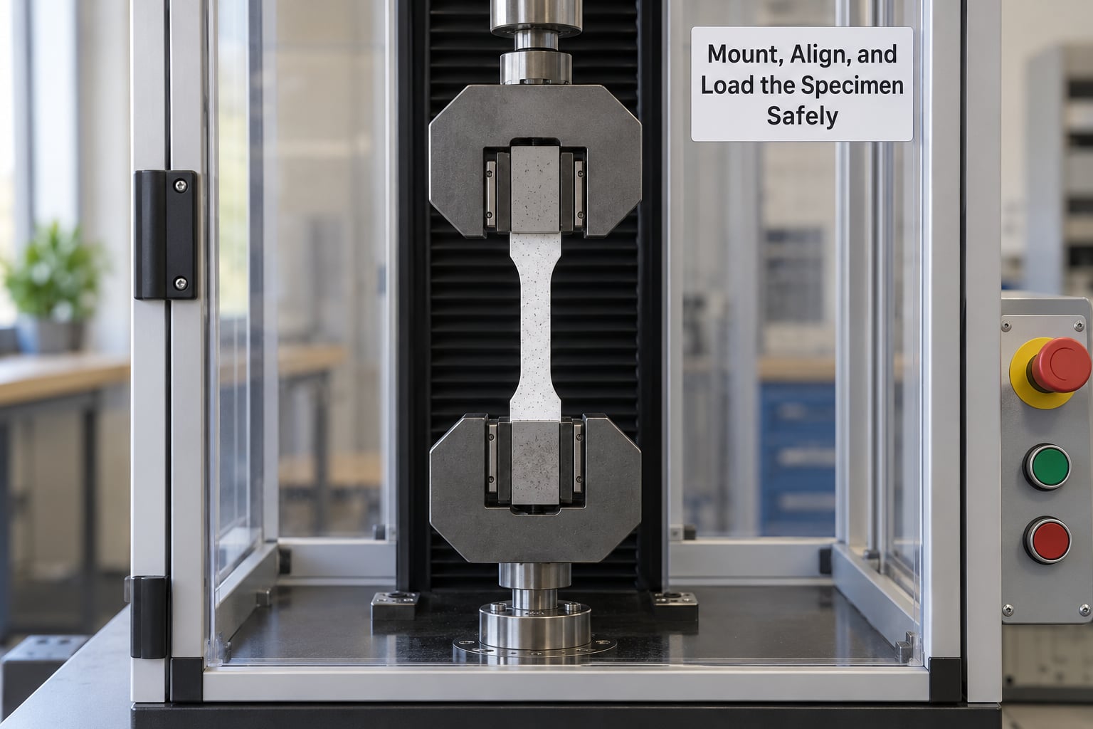
Clamp the coupon with enough length inside each jaw that the grip section never lets go, and center it so the load path runs straight down the gauge section. A specimen loaded a few degrees off-axis bends instead of pulling, and the bending stress inflates the apparent strength.
Put the transparent shield between you and the grips, and set the controls where you can reach them without leaning into the frame. Know where the emergency stop or power disconnect is before you apply load, not after.
Start with a conservative preload, well below the expected failure load. Watch the force reading and the specimen together during that first increment. If the force holds steady and the specimen sits straight, the grips, the load path and the data recording all work, and you can increase the rate.
Every tensile frame has pinch points at the grips and the crosshead, and a specimen under load stores energy. When a brittle coupon breaks it can throw fragments, and a grip that lets go can travel. Keep hands clear of the load path and out of the exclusion zone for the entire run.
6. Run Tensile Testing Printed Parts at Home
A standard load-to-failure run follows a fixed sequence. Apply the preload to take up slack in the grips and the frame. Set the crosshead speed, which is commonly 5 mm/min for rigid plastics under ISO 527 procedures, and start sampling force and displacement together at a rate fast enough to capture the peak.
Watch for two things while it runs. Slippage shows up as a sudden drop in force while the crosshead keeps moving, and it means your result is wrong. Cracking before the peak means the coupon had a flaw, usually a void, a cold layer or an undercut edge, and that specimen should be set aside and noted rather than quietly counted.
One honest warning about strain: extension from the moving crosshead is not automatically the strain in the specimen. It includes grip seating, frame deflection, grip stretch and screw compliance. For a rough comparison that is fine. For a genuine stress-strain curve and any modulus measurement, you need strain measured over the gauge section, which means an extensometer or a marker-and-video method.
7. Calculate Strength and Check the Result
Maximum engineering stress comes from the peak load divided by the original cross-sectional area. Engineering strain is the change in gauge length divided by the original gauge length, expressed as a fraction or a percentage.
Here is a worked example. A coupon with a 10 mm wide, 3 mm thick gauge section has an area of 30 mm². If it reaches a peak load of 1,080 N, then 1,080 divided by 30 equals 36 MPa. That is the ultimate tensile strength of that coupon, and every coupon in the batch gets the same treatment with its own measured dimensions and its own peak.
Engineering stress uses the original area throughout, even after the specimen necks, which is why the curve drops at the end. True stress divides by the shrinking instantaneous area and keeps rising. Published tensile strength figures are normally engineering values, so quote the same kind when you compare against a datasheet.
Record enough to let someone else repeat it: coupon dimensions, print settings, orientation, conditioning, crosshead speed, grip type, peak load, failure location, and the limits of your rig. A single neat number from a home setup is genuinely useful for ranking your own prints. It is not laboratory-grade data, and reporting it as such is how people end up designing around a number that was never real.
Common Mistakes
- Testing a finished part. Fix: print dogbone coupons in the standard’s geometry and test those.
- Changing print settings between coupons. Fix: print one batch per condition with everything held constant.
- Skipping filament drying. Fix: dry before printing and condition the finished coupons consistently.
- Grip slippage or jaw damage. Fix: increase grip length, use serrated faces, and check jaw condition between runs.
- Off-axis loading. Fix: centre the specimen carefully and watch the first preload increment.
- Too fast a crosshead speed. Fix: use the rate your chosen standard specifies and keep it identical across the batch.
- Uncalibrated force readings. Fix: calibrate the load cell against a known reference and stay inside its range.
- Too few specimens. Fix: run at least five per condition and report the spread, not just the best one.
Two habits keep results honest and people safe: write down every condition before the first pull so nothing gets quietly adjusted mid-batch, and treat any discrepancy as information about your setup before it is information about your material. If a whole batch reads 20 percent lower than the last one, look at the rig before you blame the filament.
Frequently Asked Questions
Can I perform a tensile test on a finished 3D printed part instead of a test coupon?
You can, but the result only describes that part in that fixture. Varying cross-section, holes and fillets create stress concentrations, and your grips add their own stress. That makes finished parts useful for failure analysis and go or no go checks, and unreliable for comparing materials. Print standardized dogbone coupons for any comparison you plan to rely on.
How many printed specimens do I need for a reliable home tensile test?
Five per condition is a practical minimum for home work, and more is better. Printed parts vary along their length and between jobs, so a single coupon tells you about one coupon. With five you get a rough mean and a spread. Report the spread with the result, and treat anything under three samples as a curiosity rather than data.
Is a force gauge enough to test 3D printed parts at home?
A calibrated force gauge can give you a usable peak load, which is the number most comparisons need. It is not enough for a full stress-strain curve, because you also need displacement measured over the gauge section. Add an extensometer or a marker-and-video method if you need yield behaviour and modulus, and stay inside the sensor range.
Which print orientation usually gives the highest tensile strength?
Flat on the build plate, in the XY plane, usually gives the highest tensile strength, because the load runs along continuous extruded beads rather than across layer lines. Pulling in the Z direction loads the weakest plane in the print. The gap is large, and testing coupons in both orientations is one of the most informative experiments a home rig can run.
When should I use a professional materials-testing laboratory instead?
Use a lab when the result has to survive scrutiny: safety-critical parts, regulated qualification, customer datasheets, contractual acceptance criteria or failure analysis of something that caused damage or injury. Those require calibrated instruments, documented standards and traceable measurement. Home testing is for comparing your own prints, which is a different and perfectly valid job.
Start by printing one batch of consistent coupons and running a single controlled test end to end. Once that one run is clean, with no slippage and a result you can trace back to a measured cross-section, you have a working process for tensile testing printed parts at home. Everything after that is just changing one variable at a time.