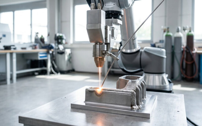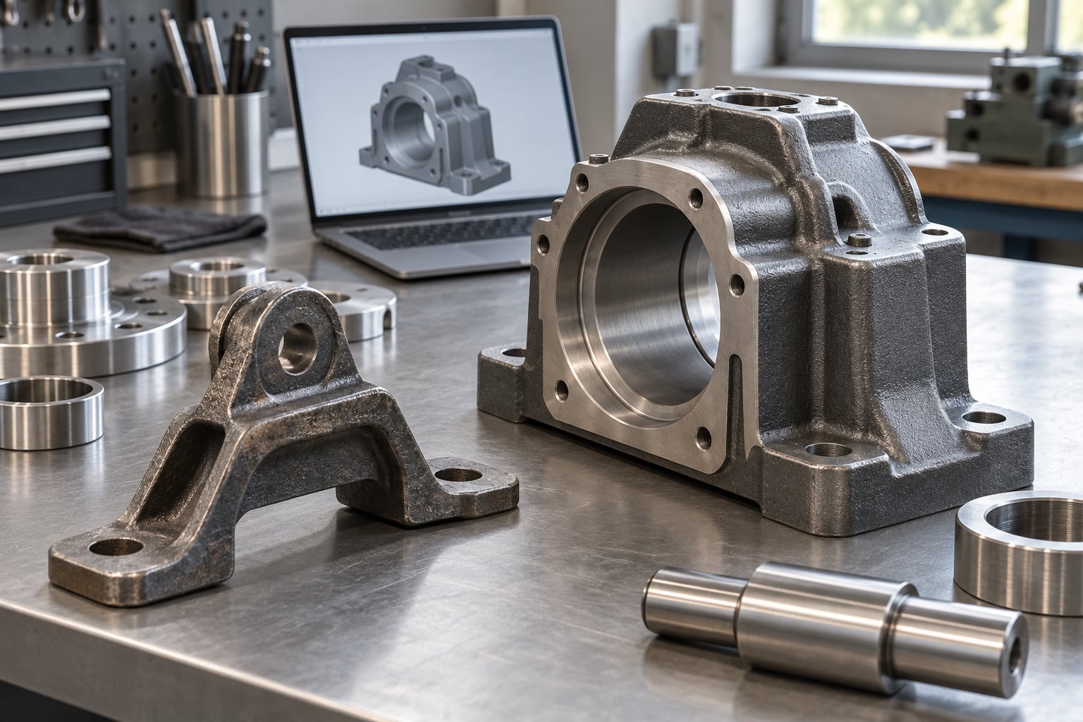
3D printing for railway and heavy equipment parts is the practice of building components layer by layer from a digital model, instead of cutting them from solid stock or casting them in a mould. It works because most maintenance demand is awkward: one part, an odd geometry, a supplier who no longer exists, and a machine that cannot wait weeks for a delivery. Print the part instead, on demand, in the material that suits the job.
This guide walks through where the technology actually earns its keep, which processes and materials fit which jobs, what the constraints are, and how a depot or service workshop moves from a one-off prototype to controlled production. It is written for maintenance engineers, depot managers, production engineers and the technicians doing the work.
Table of Contents
- 1What Is 3D Printing for Railway and Heavy Equipment Parts?
- 2Why Do Railway and Heavy Equipment Teams Use Additive Manufacturing?
- 3Which Parts Are Best Candidates for 3D Printing?
- 4How Does 3D Printing for Railway and Heavy Equipment Parts Work?
- 5Which 3D Printing Technologies Fit the Job?
- 6What Materials Can Be Used for Rail and Heavy-Duty Parts?
- 7What Design and Engineering Requirements Apply?
- 8How Does Additive Manufacturing Compare with Machining and Casting?
- 9How Much Does 3D Printing for Railway and Heavy Equipment Parts Cost?
- 10What Are the Main Risks, Limitations, and Safety Considerations?
- 11How Can a Team Move from Prototype to Production?
- 12Frequently Asked Questions
- 13Can 3D printing be used for safety-critical railway and heavy equipment parts?
- 14Which materials are most suitable for heavy equipment replacement parts?
- 15Is 3D printing cheaper than machining or casting?
- 16How long does it take to produce a 3D printed replacement part?
- 17How do you reverse engineer an old part for 3D printing?
- 18Conclusion
What Is 3D Printing for Railway and Heavy Equipment Parts?
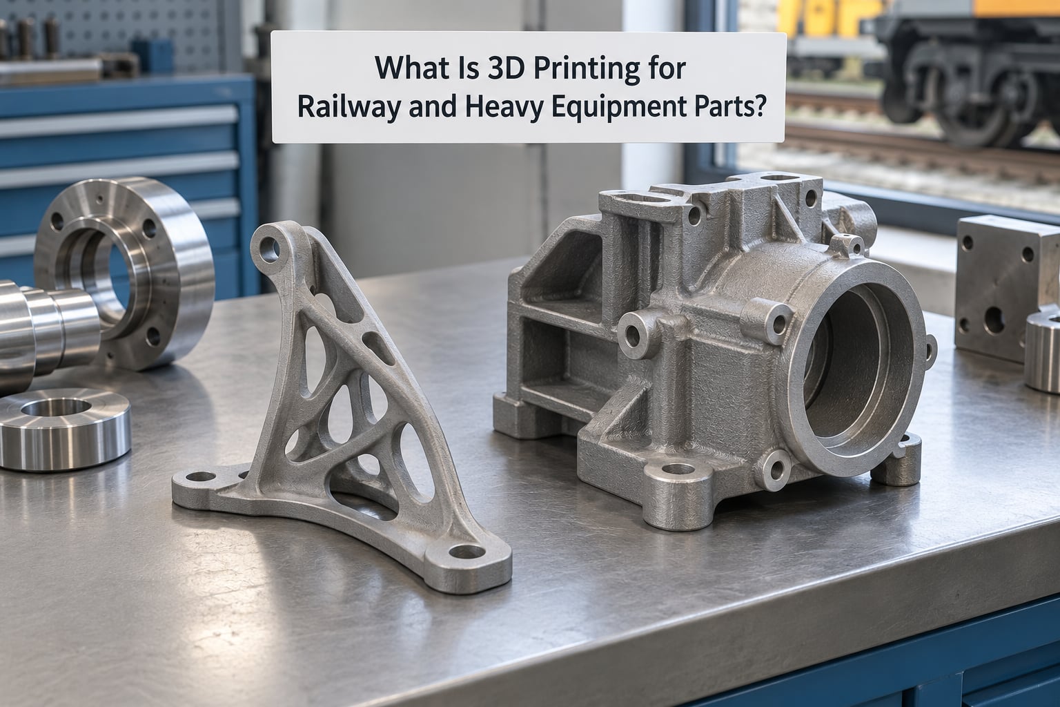
Additive manufacturing builds a solid from a thin layer of material added over and over, guided by a sliced digital model. For rail and heavy equipment work, that means a part exists because a file exists, not because a steel mill produced bar stock for it.
The contrast with conventional routes matters. Machining removes material from a block, so it needs the block, a machine time slot and a programme. Casting needs a pattern, a mould and usually a minimum run before anyone earns money back. Injection moulding needs a tool that can cost more than the fleet it serves. Additive manufacturing asks for none of that before the first part exists.
The use cases cluster into four groups. Manufacturing aids — jigs, fixtures, masking stencils, templates and gauges — are the highest-volume category because they carry no certification burden. Obsolete and low-volume spares come next: components for 30 to 50 year-old assets whose supplier has gone. Lightweighting and complex geometry matter where a machined part would be heavy, wasteful or simply difficult to tool. On-site repair closes a vehicle out in minutes rather than days.
What it does not change: a part still has to hold load, resist wear and survive its environment. Printing changes how you get there, not whether the design is sound.
Why Do Railway and Heavy Equipment Teams Use Additive Manufacturing?
Railway vehicles, excavators, loaders and mining machines stay in service for decades. That single fact drives nearly every business case.
Lead times. A reverse-engineered obsolete part can move from scan to fitted component in days rather than the weeks a machine shop quotes. When a vehicle earns money every hour it runs, that difference shows up on the maintenance budget line.
Tooling and minimum order quantities. Tool costs vanish for one-off geometry, and there is no economic minimum. A part is worth making if a machine is idle without it, even if only one will ever be needed.
Inventory. Instead of holding a shelf of slow-moving spares for a 30-year-old fleet, teams keep the files and print to demand. Storage footprint drops, obsolescence risk drops with it, and a depot can support more vehicle variants without a warehouse expansion.
Supply-chain resilience. When a supplier, a route or a region becomes a problem, a digital file can be produced at another site or another country. That flexibility is the argument that often wins approval, even when the direct cost saving is modest.
Design freedom. Consolidated parts, integrated channels, optimised lattices and ergonomic shapes that a mould could never hold. Fewer parts in an assembly usually means fewer fasteners and fewer failure points.
Difficult geometry. Deep internal channels, undercuts, complex curves and thin ribs are cheap in a printer and expensive or impossible on a mill.
Which Parts Are Best Candidates for 3D Printing?
A good candidate is low-volume, geometrically awkward, non-safety-critical, and expensive in time rather than in material.
In rail depots, the recurring list is cable guides and cover caps, masking stencils for painting and coating, scratch-protection pads for luggage racks and interior panels, handheld scanner and tool holders, inspection templates, drill and tap fixtures, and prototype housings for controls and connectors.
In heavy equipment service bays, technicians reach for hydraulic hose routing templates and service aids, castle-nut and hose-removal tools, guard and shield replacements, gussets and brackets, drill jigs for rebuilding wear items, hose clamps, and shim or spacer packs for assemblies that have relaxed.
Mining and quarry operations add wear-adjacent tooling, sensor and camera mounting brackets, and conformal protection around high-impulse areas.
A simple test: if the part is non-structural, replaced occasionally, and would otherwise cost a machine shop more in setup than in steel, it is a strong candidate. If a failure could derail a train, roll a machine, or injure someone, it needs a qualified design, a qualified supplier and documented testing — not a workshop print.
How Does 3D Printing for Railway and Heavy Equipment Parts Work?
The workflow runs from capturing the geometry to installing the part, and each stage has a purpose you should be able to name when you explain it to an auditor.
| Stage | What happens | Why it matters |
|---|---|---|
| Digital capture | 3D scanning of the existing part, or CAD from the original design data | Reverse engineering produces a model that matches reality, including wear and damage |
| Model preparation | Geometry cleanup, orientation choice, supports, tolerances and material assignment | Orientation and wall decisions set the strength of the finished part |
| Slicing | The model becomes toolpaths with layer height, infill and speed settings | The single biggest lever on quality and build time |
| Printing | Deposition or curing layer by layer in a controlled chamber | Monitor for layer shifts, recoater faults or powder spreading issues |
| Post-processing | Support removal, depowdering, stress relief, heat treatment, machining of critical faces | Printed surfaces need finishing before they seal or take a press fit |
| Inspection | Dimensional check, surface check, verification against the drawing | Catches a drifting build before the part reaches a vehicle |
| Testing and installation | Fit check on the assembly, then monitored service | Confirms real-world behaviour before the design goes into repeat use |
One detail from the field is worth repeating: reverse engineering is iterative. A first scan and print usually produces something close, a fit check reveals the gap, and a second version lands. Budget for two iterations rather than assuming one.
Which 3D Printing Technologies Fit the Job?
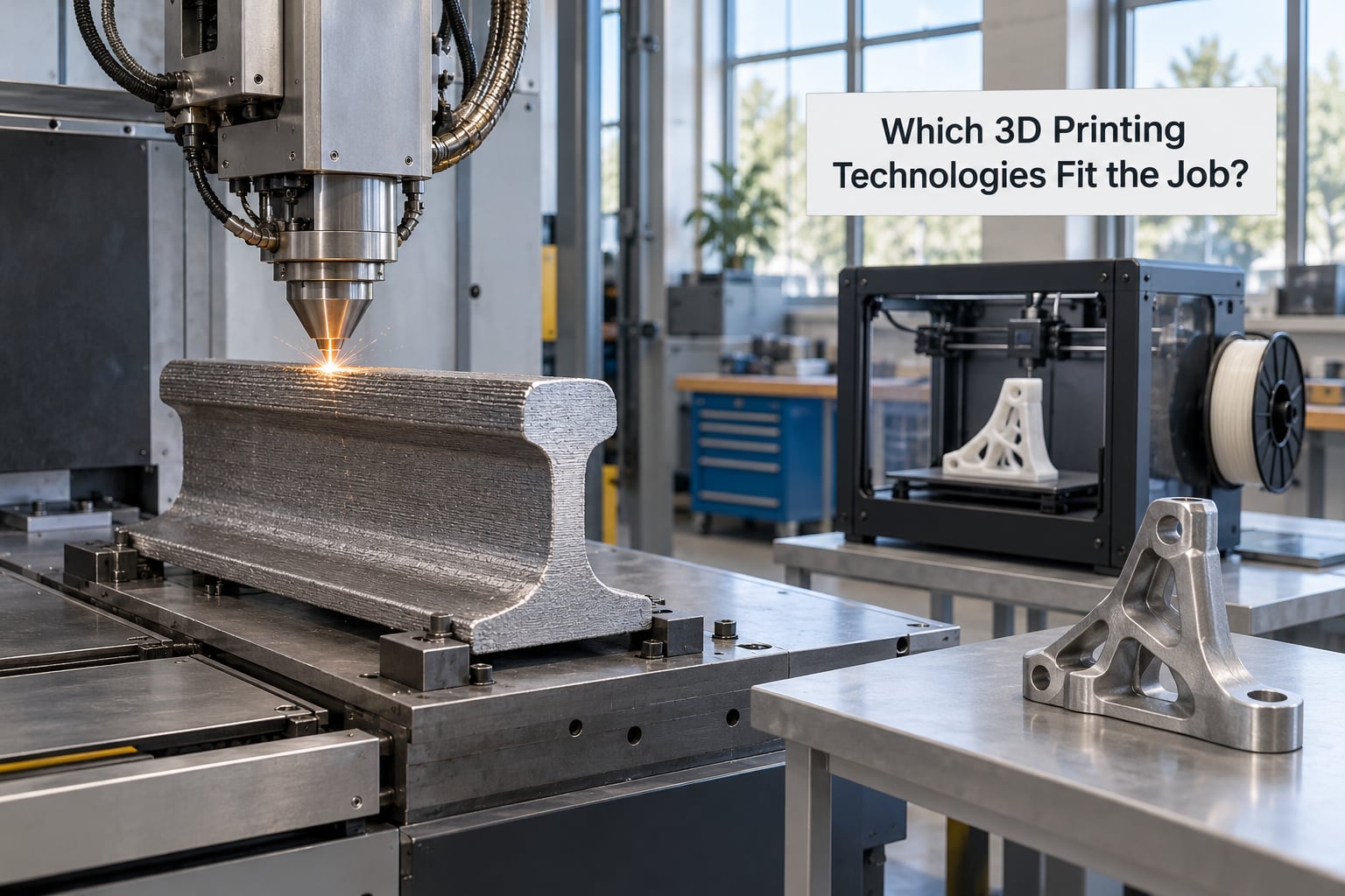
No single process covers everything. The choice comes down to part size, material, load, tolerance and how many pieces you need.
| Process | Suitable materials | Typical build size | Surface finish | Strength profile | Best fit |
|---|---|---|---|---|---|
| FFF / FDM | PLA, PETG, ABS, ASA, nylon, carbon-fibre nylon, TPU | Small to large | Rough, visible layer lines | Moderate; layer adhesion and orientation dominate | Jigs, fixtures, masking tools, guards, low-load replacement parts |
| SLA / DLP | Photopolymer resins, tough and filled variants | Small to medium | Fine, near-smooth | Good in-plane, weaker along layer planes | Fit-check models, templates, fine detail patterns |
| SLS | Nylon 12, TPU 90A, flame-retardant polymers | Medium | Matt, slightly textured, no supports needed | Consistent; good for functional production parts | Production-grade polymer spares, complex geometry, batch production |
| MJF | Nylon, TPU, engineering blends | Medium | Smooth, lighter than SLS | Consistent | Similar to SLS with faster throughput and lighter parts |
| SLM / DMLS | Stainless steels, tool steels, aluminium, titanium alloys | Small to medium | Rough, machined critical faces | High; fully dense parts, anisotropy managed by orientation | Qualified metal spares, lightweight components, repair parts |
| Metal binder jetting | Stainless and tool steels, aluminium | Large | Rough, machined after sintering | High after full density and heat treatment | Larger metal parts, short runs, parallel machine throughput |
| Directed energy deposition | Steels, nickel alloys, aluminium | Very large | Rough, machined to size | Metallurgical quality comparable to wrought stock | Repair of worn components and cladding, large structures |
For most depot and service-bay work, FFF covers the aids and light parts, and SLS covers functional polymer spares that see real handling. Metal processes come in when a qualified, load-bearing design genuinely requires them, or when wear repair justifies the equipment.
What Materials Can Be Used for Rail and Heavy-Duty Parts?
Material choice is where most workshop failures start. People default to PLA because it is easy, then discover the part sits near an engine bay or a hydraulic line.
| Material family | Strength and temperature | Environment notes | Typical use |
|---|---|---|---|
| PLA and PLA+ | Moderate; softens well below service temperatures | Poor in heat, oil and UV; not for vehicles | Appearance models and fit checks only |
| PETG, optionally with PTFE lubricant | Good toughness; workable but limited heat margin | Resists grease and moisture better than PLA; still poor above roughly 80C | Non-structural housings, cable guides, light covers, non-critical wear replacements |
| ABS and ASA | Tougher and more heat-tolerant than PLA; ASA handles UV | Good for tools and templates; poor in solvents | Jigs, fixtures, masking stencils, service tools |
| Nylon PA6 and PA12 | Strong and tough; absorbs moisture, which changes dimensions | Good wear and chemical resistance; excellent fatigue behaviour for polymers | Structural polymer parts, load-bearing brackets, gear trains in light duty |
| Carbon-fibre reinforced nylon | Stiffer and stronger than plain nylon | Low moisture uptake; fibres can abrade mating surfaces | Lightweight brackets and covers in greasy, high-handling areas |
| Glass-filled nylon | Stiff, dimensionally stable, abrasion resistant | Glass fibres wear neighbouring parts; not for mating wear surfaces | Gears, rollers and guides that see moderate abrasion |
| TPU 90A | Flexible; moderate abrasion resistance | Resists repeated flexing and abrasion | Grips, bump stops, protective sleeves, flexible ducting |
| PEEK and ULTEM | High temperature and chemical tolerance; expensive | Needs industrial equipment; flame-retardant grades exist for rail interiors | High-temperature brackets, cabin fittings, qualified applications |
| Flame-retardant thermoplastics | Varies by grade | Chosen to satisfy rail fire-safety requirements | Interior trim, covers and cabin fittings |
| Aluminium alloys | Light and strong; excellent specific strength | Fatigue and corrosion sensitive to surface condition | Lightweight structures, housings, brackets |
| Stainless and tool steels | High strength and wear resistance | Corrosion resistant; heavier and harder to machine | Qualified mechanical parts, repair inserts |
| Titanium alloys | Very high strength-to-weight, fatigue resistant | Costly; requires qualified equipment and post-processing | Corrosive environments, weight-constrained components |
Two rules keep teams out of trouble. Never place PLA or standard PETG near heat, oil, hydraulic fluid or direct sunlight. And test a candidate material against the actual fluid and temperature of the machine, not against a datasheet in isolation.
What Design and Engineering Requirements Apply?
A printed part is still an engineered part. Several design decisions carry more weight than usual because the process builds in layers.
Layer direction and grain. The layer plane is the weak plane. Orient the part so that primary loads run along the layers, not across them, and rotate parts so layer boundaries never sit where bending stress peaks.
Load paths. Avoid relying on the first printed layer to carry a bolt load. Add bosses and local thickening around fastener holes so clamping force spreads into the material rather than splitting a layer.
Wall thickness and ribs. Thin printed walls delaminate. Use ribs and adequate wall thickness for stiffness, which is cheaper in material and time than simply printing solid.
Tolerances and press fits. Printed parts need clearance for fit. Where a face must locate precisely, machine or shim it rather than trusting the layer surface. Print orientation and shrinkage, especially in nylon, change effective dimensions.
Fatigue and vibration. Rail bogies and heavy equipment see constant cyclic loading and vibration. Metal printed parts carry anisotropy, so fatigue life needs testing rather than assumption.
Environment. Temperature, oil, fuel, hydraulic fluid, hydraulic pressure, dust, salt and UV each remove material options from the list. Write the exposure down before selecting the polymer.
Design intent. Where an original equipment manufacturer drawing exists, keep the load paths, mounting points and material intent intact. Do not quietly upgrade a part outside its approved envelope.
How Does Additive Manufacturing Compare with Machining and Casting?
Each route wins on different criteria. The honest answer is that the manufacturing route should follow the part, not the other way round.
| Criterion | Additive manufacturing | Machining | Casting |
|---|---|---|---|
| Lead time for one part | Days | Days to weeks | Weeks |
| Tooling and setup | Almost none | Programming, fixtures, bar stock | Pattern and mould |
| Economics at low volume | Strong | Weak below roughly 200 pieces | Weak |
| Economics at high volume | Weak per unit | Strong | Strongest at very high volume |
| Repeatability | Good within process capability; needs monitoring | Very high | High once the process is stable |
| Material range | Polymers, metals, composites, with qualification limits | Almost any machinable material | Cast alloys and polymers |
| Largest part size | Limited by build chamber | Limited by machine envelope | Large parts possible |
| Internal geometry | Excellent | Difficult | Cores possible, expensive |
| Surface finish | As-built or lightly finished; needs machining for sealing faces | Excellent | Good with secondary operations |
| Supply-chain resilience | File plus any qualified printer | Depends on stock and supplier | Depends heavily on foundry capacity |
Rule of thumb: printed parts suit one-offs and low volumes, machining suits repeat batches of stable geometry, and casting suits large runs of simple castable shapes. The break-even point differs by material and is quoted by operators at roughly a couple of hundred metal pieces and a couple of thousand polymer pieces — a useful order of magnitude rather than a promise.
How Much Does 3D Printing for Railway and Heavy Equipment Parts Cost?
There is no single price, and anyone quoting one for your part without seeing the geometry is guessing. Quote the whole job, not just the machine time.
The drivers that move the number most are material choice and volume of material used, part size relative to the build chamber, surface and tolerance requirements, post-processing, inspection and certification, quantity ordered, and engineering and supervision time.
Add the cost that is easy to forget: de-powdering and cleaning, machining of critical faces, heat treatment for metal, labour for fit checking, and the setup cost of a part that needs a second iteration.
Economics by scenario. A prototype or fit-check model is almost always cheaper printed than machined, because the machining setup dominates the cost. A low-volume replacement for an obsolete part usually wins, because the alternative is an OEM price with a long delivery or nothing at all. A repeat batch of a stable part is where printing loses, and shops switch back to machining or casting once the volume justifies it.
The comparison that matters is against the alternative, not against zero. A printed part that returns a machine to service today has already beaten a spare sitting in a shipping container for six weeks.
What Are the Main Risks, Limitations, and Safety Considerations?
The honest limitations are what separate a useful guide from a brochure.
Wear surfaces and continuous torque. Printed gears and wear parts run noisier and can wear in a non-linear way. Fibre-reinforced materials improve stiffness but the fibres can abrade the mating surface. For high-torque, continuously running drives, use engineered polymers only after testing, or use a metal part.
Anisotropy and fatigue. Strength differs along and across the layer plane. Anything subject to repeated cyclic loading needs a fatigue assessment, not a static strength figure.
Porosity and integrity in metals. Printed metal parts can contain porosity and unmelted powder. Densification, heat treatment and nondestructive inspection are standard requirements for qualified applications.
Heat, oil and chemicals. Thermoplastics soften near their melting window. A printed gear in an oil-filled gauge drive has worked for people for years, but that is a validation result, not a material guarantee.
Certification and traceability. Rail interiors fall under fire-safety requirements such as EN 45545-2, which covers reaction to fire and smoke and toxicity ratings. Safety-critical mechanical parts fall under the vehicle’s own approval framework and usually require the equipment manufacturer’s involvement. A printed part carries no approval on its own.
Fit and dimensional drift. Layer lines and post-processing mean printed faces rarely mate directly. Light filing, shimming or machining is normal.
Digital file security. Files for spare parts are valuable intellectual property. Control access to the repository, log who changes what, and settle ownership and licensing terms in writing.
Machine and operator safety. Polymer powder handling, extraction and filtration, metal powder handling with its dust and fume exposure, and fume extraction for resin printing all need proper equipment. Follow the machine manual and your local regulations.
Bring engineering, quality, procurement and the safety or regulatory function into the decision early. A printed part that quality later rejects costs more than the machine time that produced it.
How Can a Team Move from Prototype to Production?
Most teams succeed by starting small and documenting as they go. A staged path looks like this.
1. Pick the right first part. Choose a non-structural component with measurable value — a masking stencil, a scan template, a hose-routing guide. Prove the workflow before touching anything load-bearing.
2. Document the use case. Record the environment, loads, temperature, fluids and how often the part is replaced. This page is what a reviewer will ask for later.
3. Capture the as-built geometry. Scan the existing part with a 3D scanner or measure it and model it in CAD. Software such as Fusion 360, SolidWorks or Rhino suits machinists because the modelling habits transfer directly.
4. Select process and material. Match the material to the environment, not to what the machine can print. Decide whether the part lives in-house or goes to a print bureau based on volume, capability and how often you will reprint.
5. Validate geometry and material. Print a fit-check model first. Then produce test parts and, where the application warrants it, run them to failure in a controlled environment to establish real life data.
6. Inspect production output. Define what is checked, how often, and by whom. Record material batch, machine, settings and orientation for every production part.
7. Install under controlled conditions. Run the first parts in service on a limited fleet, with inspection intervals, and gather data before standard release.
8. Scale only after results are reviewed. Publish the findings to the engineering, quality and procurement teams, then extend to the rest of the fleet if the results hold.
Teams that print in-house own the whole loop and the learning curve. Shops with intermittent demand often do better outsourcing early parts to a bureau, then bringing volume in-house once they know the real process requirements.
Frequently Asked Questions
Can 3D printing be used for safety-critical railway and heavy equipment parts?
It can be, but only when the part meets the applicable design, material, testing, qualification, inspection and traceability requirements. Safety-critical applications normally require documented engineering approval, a qualified material and supplier, defined inspection methods and formal acceptance testing, which often means the original equipment manufacturer’s involvement. Most teams start with non-critical aids and non-structural parts, and only move towards qualified components once the process and its documentation are proven.
Which materials are most suitable for heavy equipment replacement parts?
It depends on load, temperature, wear, impact, corrosion and geometry. Filled polymers and engineering polymers such as nylon or carbon-fibre nylon work for non-critical housings, covers, guides and cable management near oil and grease. Filled nylons handle moderate abrasion better than plain polymers but their fibres can wear neighbouring parts. Aluminium, stainless steel and titanium alloys cover load-bearing and wear applications, while PEEK and similar high-temperature polymers suit hot, chemically aggressive locations.
Is 3D printing cheaper than machining or casting?
For prototypes, obsolete single parts, complex internal geometry and small production runs, it usually is, because there is no tooling, pattern or minimum order quantity to amortise. For repeat batches of a simple, stable part in large quantities, machining or casting is normally cheaper per unit and offers better surface finish and repeatability. The right comparison is always against the realistic alternative, including the cost of waiting for a spare that arrives in six weeks.
How long does it take to produce a 3D printed replacement part?
Lead time depends on the process, size, material, finish and testing requirements. A simple polymer prototype or fit-check model can be designed and printed within a day or two, while a functional polymer spare with reverse engineering and a fit check takes several days. A large metal production part with post-processing and inspection typically takes weeks, and a qualified component with formal testing takes longer still. Reverse engineering usually needs two print iterations, so plan for it.
How do you reverse engineer an old part for 3D printing?
Scan the existing part with a structured-light or laser scanner, or measure it and model it in CAD if the part is simple. Clean the mesh, repair small defects, then set the orientation and tolerances so the part fits the assembly rather than the scan. Print a cheap fit-check model first, adjust where it does not mate, then print in the production material. Expect two iterations, and record the final dimensions as a controlled model rather than a scan file.
Conclusion
Start with the first action for your situation. Railway operators pick a non-critical aid such as a masking stencil or a cable guide cover cap and print it on site. Heavy equipment service teams scan an obsolete OEM component and compare the printed route against the replacement price and the delivery wait. Production engineers review the weak-plane and tolerance constraints before committing a design, and managers pick one part with measurable value rather than a whole fleet rollout.
Capture the geometry properly, match the material to the actual heat, oil and load in that corner of the machine, and compare the printed route honestly against machining, casting and simply ordering the spare. Print test parts, run them under controlled conditions, record the results, and only scale up once engineering, quality and procurement have signed off on the evidence.