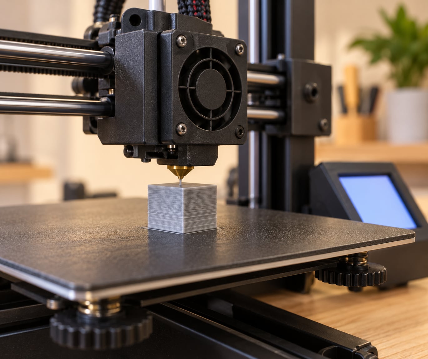
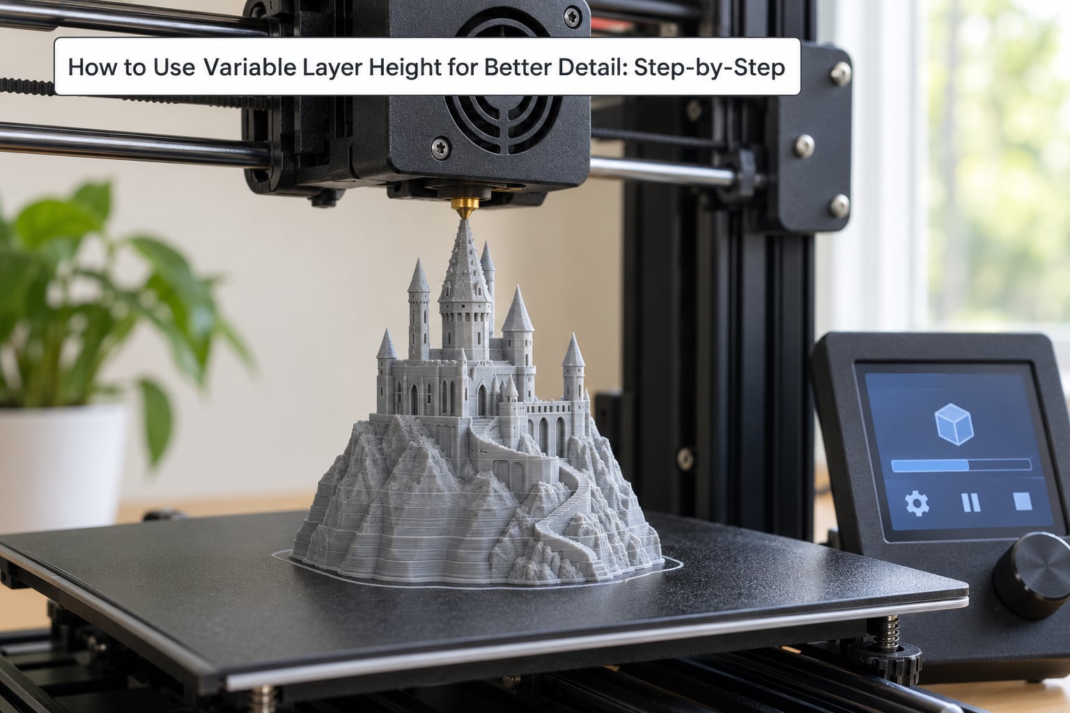
Variable layer height is a slicer feature that varies the thickness of each layer across a single print, using thin layers on slopes, curves and small features to soften the staircase effect, and thicker layers on straight vertical walls to save time. Learning how to use variable layer height for better detail comes down to three things: a sensible minimum and maximum layer height, feature thresholds that put the fine layers where they matter, and speeds and cooling that suit both extremes. On a 0.4 mm nozzle, a range of 0.12 mm to 0.28 mm is a sane starting point.
It is a genuinely useful setting, but it is also the one most often blamed for problems it did not cause. A cone that bands at the top is usually not a variable layer height failure. The fix is rarely more sliders.
Table of Contents
- 1What You Need
- 2How to Use Variable Layer Height for Better Detail: Step-by-Step
- 31. Establish a Reliable Baseline Print
- 42. Set the Minimum and Maximum Layer Heights
- 53. Decide Where Extra Detail Is Needed
- 64. Balance Layer Height with Print Speed
- 75. Preview and Test Before Making a Full Print
- 86. Save a Reusable Slicer Profile
- 9Common Mistakes
- 10Setting the minimum below what the extruder can deliver
- 11Blaming variable layer height for banding that comes from somewhere else
- 12Abrupt transitions where thick meets thin
- 13Ignoring nozzle geometry
- 14Weak first layer
- 15Cooling that cannot follow the changes
- 16Turning it on for every model
- 17Trusting the colour map without a test print
- 18Frequently Asked Questions
- 19How is variable layer height different from adaptive layer height?
- 20What is the best maximum layer height for an FDM printer?
- 21Does variable layer height slow down the entire print?
- 22Can variable layer height improve small text and facial details?
- 23Can resin printers use variable layer height?
- 24Conclusion
What You Need
Almost any FDM setup can do this. You need a slicer that supports the feature, a model to test on, and roughly an hour of quiet machine time.
- A slicer with variable or adaptive layers. PrusaSlicer, Cura, Bambu Studio and OrcaSlicer all ship with it. Menu names differ between each one and between versions, so treat the paths below as a map rather than a contract.
- A test model you already know. A 3DBenchy or a calibration cube with embossed text works well, because you will recognise when the corners, letters or hull start to go wrong.
- A baseline print at one fixed layer height. Print it before you touch anything, so you have a comparison.
- A known nozzle size. A 0.4 mm nozzle and a 0.6 mm nozzle need completely different ranges.
One honest warning before you start: entry-level machines with a single-screw Z axis and a coupler can wobble as the nozzle changes height mid-print. Variable layer height asks more of your Z mechanics than a fixed height does, because the machine keeps chasing small steps during the whole print.
How to Use Variable Layer Height for Better Detail: Step-by-Step
1. Establish a Reliable Baseline Print
Slice the test model at a single fixed height, usually 0.2 mm on a 0.4 mm nozzle, with your normal speed, temperature and cooling settings. Print it and keep it.
This baseline is the whole point of the exercise. Without it, when the adaptive version looks rough, you cannot tell whether the adaptive setting caused it or whether something else was already off. Reviewers on r/3Dprinting and r/FixMyPrint repeatedly describe walls that “look like I used variable layer height” when the real cause is a tuning problem that was present all along.
If the baseline already bands, fix that first. No amount of layer height variation will rescue it.
2. Set the Minimum and Maximum Layer Heights
Open your slicer’s layer height settings and find two fields: the initial layer height, which acts as the ceiling, and the minimum layer height, which acts as the floor. In most slicers, the top field is the maximum the adaptive logic is allowed to use.
The maximum should sit at roughly 75 to 80 percent of your nozzle diameter. That gives about 0.28 to 0.30 mm on a 0.4 mm nozzle, and about 0.42 to 0.48 mm on a 0.6 mm nozzle.
The minimum needs more care. A thin layer means a short extrusion, and a short extrusion is harder to flow consistently. Below about 0.10 mm on a bowden-style machine, extrusion width problems show up as under-extrusion, gaps and occasional nozzle clogs.
If you want to know what your printer truly manages, print a test with ten uniform layers at the minimum height you have set. Examine each one for a complete, even bead with no ridges or gaps on its sides. Then step down another 0.02 mm and repeat.
3. Decide Where Extra Detail Is Needed
This is where the feature earns its keep, and it is the part that requires judgment rather than a default setting. Most slicers judge each layer’s height from the slope of the surface at that height: shallow angles get thin layers, steep or flat walls get thick ones.
Think about where detail is actually visible on your model. Faces, hair, fingers, engraved text, a logo raised off a panel, and the curve of a vase are all worth the extra layers. A tall straight wall on the back of the same figurine is not.
You can tune the decision with a slope or variation threshold in most slicers. A higher threshold makes the slicer more willing to use thin layers, which looks better but costs more time and puts more demand on your extruder. A lower threshold is faster and usually more reliable.
Some slicers also let you paint layer height directly onto a face of the model. That is the reliable route for something like a helmet, where you want a uniform wall thickness through the shell but thin layers across a curved cheek plate.
4. Balance Layer Height with Print Speed
A layer height change changes the volume of plastic laid in a very short distance, so speed and cooling have to follow the change.
Keep outer wall speed modest on the fine layers. Around 50 to 60 mm/s is a common choice for detail work, because at high speed the nozzle has less time to place a short, thick bead cleanly. You can let thicker regions run faster if your machine is rigid enough to handle it, and if your filament and hotend allow it.
Watch cooling on overhangs and on small horizontal details. Thin layers have less material to hold themselves up, and users on r/BambuLab_Community point out that conical surfaces are where problems show up first. If a detail sags, lower the minimum layer height slightly, or reduce the threshold so the slicer thins those layers less.
5. Preview and Test Before Making a Full Print
After slicing, open the preview and switch to the layer height map, the colour-coded view where each Z height gets its own colour. Blue, green and red regions tell you where the slicer decided to go thin and where it stayed thick.
If you are surprised by the map, adjust and re-slice rather than printing. A model that is mostly red with thin bands near a face is working as intended; a model that is multicoloured everywhere is slicing a lot of very short layers, and that is usually where under-extrusion and time loss come from.
Use the timing estimate to sanity-check the trade-off. A typical figurine printed at a fixed 0.2 mm often lands in the high single-digit hours; the same model at a fixed 0.12 mm can take half again as long. The adaptive version usually lands between the two, and often much closer to the fixed fine print than to the coarse one, because the detail areas are a small fraction of the total volume.
Then print the calibration object before you print the real model. Look at the embossed text, the roof overhang, the sharp corners and the curved hull. Compare all four against your baseline.
One thing the preview will not tell you is whether your Z axis can physically hit those fractional heights reliably. A layer height of 0.16 mm on a machine with 400 step-per-mm Z and 16 microsteps is a position the hardware approximates rather than reaches, and posts in r/prusa3d describe that as the hidden cause of conical banding on apparently healthy printers.
6. Save a Reusable Slicer Profile
Once a test print passes, save the settings as a named profile and write down what it assumes: nozzle size, material, ambient temperature, whether the machine is enclosed.
Detail profiles behave differently on different materials. A profile tuned for PLA in a warm room will not transfer cleanly to PETG, and a profile tuned for an open-frame printer can overshoot on an enclosed one.
Keep a second profile with a narrow range, for example 0.16 mm to 0.20 mm, for parts that need predictable Z behaviour more than they need a smooth surface.
Common Mistakes
Setting the minimum below what the extruder can deliver
The symptom is intermittent gaps, stringing between features and an occasional clog partway through a fine detail area. The fix is to raise the minimum layer height until extrusion is clean. For most 0.4 mm setups that means landing between 0.10 and 0.14 mm, not chasing 0.06 mm.
Blaming variable layer height for banding that comes from somewhere else
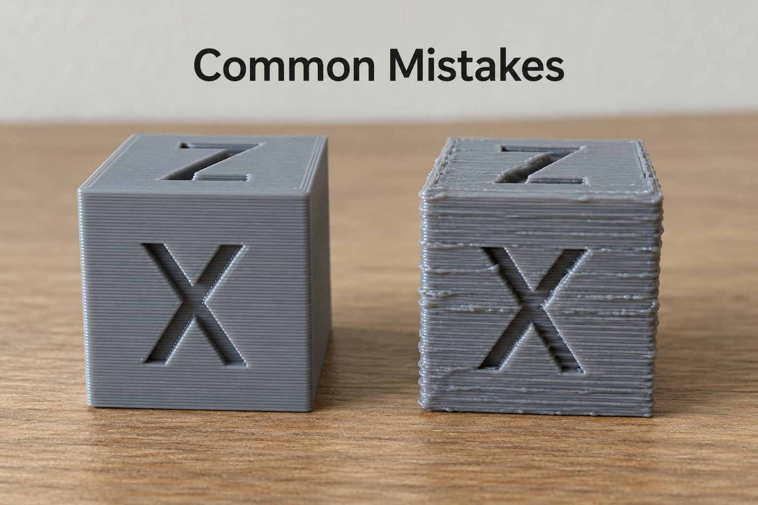
Banding on a curve can come from poor linear advance tuning, a loose belts, a warped Z axis or a hotend that cannot hold temperature. A recurring cluster of banding reports at 0.12 mm with a 60 mm/s outer wall appears whether or not adaptive layers are enabled.
The diagnostic is simple. Print the same curved feature at a single fixed height. If it still bands, variable layer height is innocent and you have a tuning problem.
Abrupt transitions where thick meets thin
You can see the seam as a visible ridge. Most slicers offer a smoothing or transition-height option that ramps gradually through intermediate heights instead of jumping, and a stepped ramp of roughly 0.28, 0.24, 0.18, 0.14 and 0.12 mm spreads the stress across several layers. Leave that option on, and keep the ramp short enough that it does not eat the detail you wanted in the first place.
Ignoring nozzle geometry
A 0.4 mm nozzle cannot print a clean 0.4 mm layer. The upper bound is a ratio, not a diameter, which is why 75 to 80 percent is the number people quote. Setting the maximum to the full nozzle diameter produces ridges and underextruded top surfaces on sloped features.
Weak first layer
Variable layers often make the first layer thinner if your slicer applies the minimum from layer one. Keep the first layer at a fixed, reliable height, and make sure the bed is clean, the Z offset is right and the nozzle was not dragged before the first lines were laid. Everything above a poor first layer tends to inherit the problem.
Cooling that cannot follow the changes
Fine layers need more airflow per unit of plastic, thicker layers need less. If the fan is on a fixed profile tuned for one height, the other extreme suffers. Use a height-dependent or object-height-dependent cooling curve if your slicer has one.
Turning it on for every model
Flat parts, large functional components and anything with a tight tolerance rarely benefit. A flat lid printed at 0.2 to 0.28 mm saves time and keeps its Z behaviour predictable. Save the adaptive profile for the models where surface quality is visible.
Trusting the colour map without a test print
The layer height map shows the slicer’s intent, not the printer’s execution. It cannot show a Z axis that misses fractional heights, an extruder that stutters on short moves, or a hotend that drifts in temperature. One calibration print tells you more than any amount of preview.
Frequently Asked Questions
How is variable layer height different from adaptive layer height?
They are usually the same feature under two names. PrusaSlicer calls it variable layer height, Cura and OrcaSlicer call it adaptive layers, and Bambu Studio exposes an adaptive layer height toggle under the layer height field. The naming differs; the behaviour does not. Check which one your version of your slicer uses before looking for settings that are not there.
What is the best maximum layer height for an FDM printer?
Roughly 75 to 80 percent of your nozzle diameter is the widely used ceiling. On a 0.4 mm nozzle that is about 0.28 to 0.30 mm, and on a 0.6 mm nozzle about 0.42 to 0.48 mm. Going beyond that ratio leaves the nozzle scratching ridges into the previous layer instead of laying a clean bead on top of it.
Does variable layer height slow down the entire print?
No. Only the regions the slicer marks as detailed get the thin layers, and on most models those regions are a small share of the total volume. A figurine with fine detail up top and a plain wall below often prints only modestly longer than a fixed coarse version, while still landing well under the time a uniform fine-layer print would take. The estimate in your slicer preview tells you the real number.
Can variable layer height improve small text and facial details?
Yes, that is where it helps most. Embossed text, eyes, fingers and hair sit on curved or angled surfaces, which is exactly the geometry the slicer detects and responds to with thin layers. The improvement is real but modest, and it is capped by your nozzle size, your Z axis precision and the cooling available for those small features.
Can resin printers use variable layer height?
Generally no. Resin printers build with a consistent Z step set by the machine, and layer height is normally a single value applied to the whole job in the slicer. Some resin software offers a first-layer exception or a partially hollowed bottom region, but the true per-slice adaptive behaviour described here is an FDM slicing feature driven by mesh geometry analysis.
Conclusion
Print a model you know at one fixed layer height first, so you have something honest to compare against. Then set your maximum to about 75 to 80 percent of your nozzle diameter and your minimum to a value where extrusion stays clean, slice the calibration object, and read the layer height map before you commit hours of machine time.
If the test print shows banding on curves, check your Z axis and extrusion tuning before you blame the adaptive setting. Once a profile passes on your own machine, save it, name it after the nozzle and material it assumes, and refine it from there.