How to print clearance for moving assemblies comes down to one number: the gap you deliberately model between a pin and its socket, plus a small test coupon that proves the gap on your printer. On a desktop FDM machine, start at 0.25 to 0.30mm of total diametral clearance for a sliding fit and 0.40 to 0.50mm for a joint that has to swing freely, then halve those values for MSLA resin. The design work is an hour, the test print is twenty minutes.
Total diametral clearance means the gap measured across the whole bore, not the gap on each side. A 5mm shaft in a 5.30mm bore has 0.30mm of clearance, not 0.60mm. Getting this backwards is the most common reason a design that looks generous on screen arrives as a solid lump.
Printers cannot hold nominal CAD dimensions. Plastic shrinks as it cools, extrusion width blooms outward past the line you asked for, and every round hole is really a polygon of straight chords that cut inside the curve you drew. Clearance absorbs all three. Without it, your hinge, slider or gear train prints as one welded piece no matter how carefully you drew it.
What follows is the workflow I use: pick a starting number from a table, print a stepped coupon, measure it with calipers, add the real errors back in, then test the full motion under load before you commit filament to the final parts.
Table of Contents
- 1What You Need
- 2Step-by-Step: How to Print Clearance for Moving Assemblies
- 3Step 1: Define the Motion and Contact Surfaces
- 4Step 2: Choose a Starting Clearance Range
- 5Step 3: Model and Print a Calibration Coupler
- 6Step 4: Add Printer and Material Tolerances
- 7Step 5: Test the Full Motion Under Real Loads
- 8Step 6: Tune the Design and Repeat the Print
- 9Common Mistakes
- 10Frequently Asked Questions
- 11How much clearance should I print for a moving 3D printed assembly?
- 12Should I use clearance holes for FDM or resin 3D printing?
- 13How do I compensate for the dimensional accuracy of my 3D printer?
- 14What is the best way to test clearance before printing a full assembly?
- 15How can I tell if a moving part has too much clearance?
- 16Should I design a perfect fit or leave room for post-processing?
- 17Conclusion
What You Need
You need four things, and only one of them is the printer.
- A CAD tool — Fusion 360, SolidWorks, Onshape or FreeCAD all work. What matters is that you can apply an offset to a face or a hole, because you will be adjusting hole size more than once.
- A slicer you actually know — PrusaSlicer, OrcaSlicer or Cura. Menu names shift between versions, so check the label rather than trusting a screenshot from a two-year-old thread.
- A digital caliper with 0.01mm resolution — the accuracy on cheap calipers is usually around 0.02 to 0.03mm, which is coarser than the clearances you are chasing. Measure the same hole at three depths and average them; the first layers near the bed are almost always the tightest.
- Small hole gauges or a pin set — a set of ground dowel pins lets you check fit by feel in seconds instead of reading numbers off a caliper jaw.
- The actual material in the actual spool — wet nylon and dry nylon print differently, and a new roll of PETG from a different lot can shift a bore by a few hundredths of a millimetre.
Worth adding if you can get one: a small heated plate or a heat gun for breaking in a tight print-in-place mechanism, and a bottle of isopropyl alcohol for cleaning the printed bore before you measure anything. Finger oils push a caliper reading around more than most people expect.
Step-by-Step: How to Print Clearance for Moving Assemblies
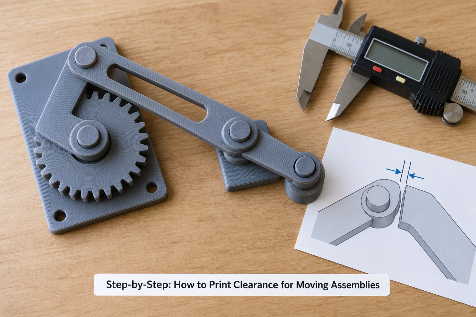
Step 1: Define the Motion and Contact Surfaces
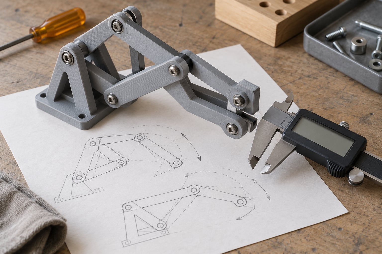
Before you touch a dimension, work out how each part actually moves. Draw the travel path of the moving part on paper, mark where it pivots, and list every surface the two parts touch along that path.
Load direction matters as much as geometry. A hinge pin carrying a lid pushes sideways against the top of its socket. A slider in a guide rail is pushed against one wall and pulled against the other. A gear only touches at the tooth flanks and needs backlash in the direction of rotation, not everywhere.
Now note what the assembly has to do at the end of travel: stop, snap over centre, hold position under gravity, or fall back. Parts that must hold a position need friction or a stop feature, which usually means slightly more clearance than a part that simply rotates.
Finish by listing the two or three surfaces that actually carry the load. Those are the ones that need careful geometry and chamfers. Everything else is cosmetic and can tolerate sloppy tolerances.
Step 2: Choose a Starting Clearance Range
Start from the table below. The values are total diametral clearance, measured across the bore, except where a row says otherwise. Treat them as the first guess, not as a promise — Step 3 is what turns them into a real number for your printer.
| Fit type | Desktop FDM | MSLA resin | How it behaves |
|---|---|---|---|
| Free-moving pivot, no load | 0.40 to 0.50mm | 0.20 to 0.25mm | Rotates or swings with a little wobble you can feel but not see |
| Sliding fit in a guide rail | 0.25 to 0.30mm | 0.15 to 0.18mm | Slides along its axis with light drag at the tightest point |
| Snug push fit, hand assembled | 0.15 to 0.20mm | 0.10 to 0.12mm | Needs a firm push to click home and stays put without glue |
| Press fit | 0.00 to minus 0.10mm | 0.00 to minus 0.05mm | Assembly needs a clamp, a jig or gentle heat |
| Gear mesh, per mesh | 0.15 to 0.20mm | 0.08 to 0.10mm | Teeth pass without jamming and drive forward only |
| Print-in-place pin in socket (per side) | 0.30mm | 0.15mm | Hinges freely after a short break-in rocking motion |
Two things to keep in mind while reading that table. Resin numbers are smaller because a masked LCD printer holds geometry far better than an extruded layer, and its failure mode is fusing solid rather than drifting. FDM numbers are larger because the error compounds over layers.
For anything with a shaft running through a bore, add a chamfer or fillet at the bore entry. A 0.5mm chamfer at 45 degrees removes the sharp edge that slices your fingers and stops the shaft edge from shaving plastic off the entry, which is what turns a running fit into a press fit after a few cycles.
Step 3: Model and Print a Calibration Coupler
Build a test piece instead of guessing. A coupler is two blocks joined by a pin, or more usefully a flat plate with a row of bores at 0.10mm increments: 4.80, 4.90, 5.00, 5.10, 5.20, 5.30 and 5.40mm. Print a matching 5.00mm pin on the same plate in the same orientation, and the row becomes a gauge you can use for years.
Orientation decides how honest the coupon is. Print bores horizontally so the circular section is built from stacked perimeters, which is how a real bore in a moving part is built too. A bore printed standing on end picks up chord error in every layer and measures smaller than it will actually be in the part that matters.
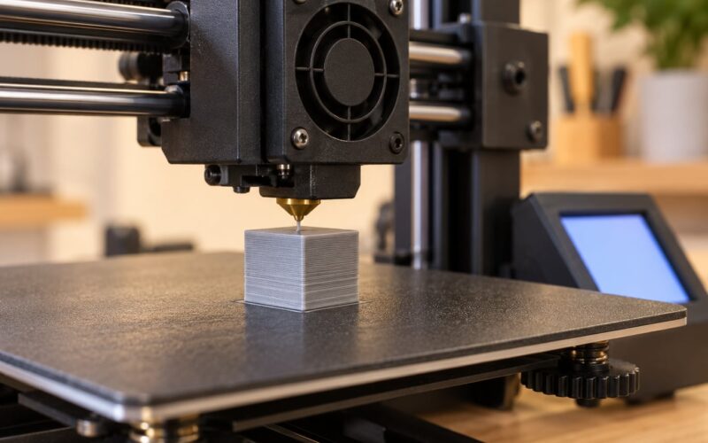
Keep the coupon flat on the bed with no brim or raft, so you can see the first-layer compression for what it is. Print it in the same material and at the same layer height as the final part, because a coupon at 0.08mm layers tells you nothing about a part printed at 0.28mm.
Measure every bore with calipers at three depths. Write the difference between nominal and measured on the plate itself with a marker. Most people find their bore is 0.05 to 0.15mm undersize, and that number is the single most useful thing on the whole object.
On resin, the equivalent check is a flat panel printed against the build plate and one printed with holes facing the light, so you can separate suction and shadow effects from ordinary shrinkage.
Step 4: Add Printer and Material Tolerances
Now build the real error budget. Every source below eats into your clearance, and most of them eat it in the same direction: bores come out small.
| Error source | Typical effect on a bore | How to compensate |
|---|---|---|
| Hole chord error | 0.03 to 0.08mm undersize on a 5mm hole with a 0.4mm nozzle | Set horizontal expansion, or model the bore 0.10mm oversize |
| Plastic shrinkage on cooling | PLA and PETG about 0.3 to 0.5%; ABS and ASA higher; wet nylon more again | Bake and dry filament, and design features large enough that the shrinkage is small relative to the gap |
| Elephant’s foot | First one to three layers swell outward and close the gap at the bed end | Elephant foot compensation, a chamfer at the bore mouth, or simply keep the bore off the first layer |
| Flow and extrusion width variation | Over-extruded lines push inward, usually 0.02 to 0.05mm | Run a flow calibration before the coupon, then print it |
| Z-height and layer shift | Bore wanders instead of closing, which feels worse than a small gap | Tighten belt tension, level the bed, check gantry squareness |
| Heat creep in a bore | Bore shrinks mid-height on long slow prints | Add a cooling fan, cut the wall count, or split the bore into two short sections |
Horizontal expansion and elephant foot compensation are the two settings worth learning properly. Horizontal expansion pushes every solid wall outward, which enlarges bores and narrows pegs at once, so it fixes a tight fit and breaks a loose one in the same click. Elephant foot compensation only touches the first layers, which is exactly the layer that closes the mouth of a bore sitting on the bed.
Material choice follows the mechanism. PLA prints beautifully and then cracks around a hinge pin under repeated flexing. PETG survives the flexing and holds a consistent bore. ABS and ASA warp, so an assembly with a long bore needs a brim or an enclosure. Nylon absorbs moisture and swells, which quietly grows a fitted shaft overnight, so dry filament and print a coupon from the same dried spool.
Step 5: Test the Full Motion Under Real Loads
A dry fit means assembling the parts by hand and moving them through the full range, not just pushing them together once. Work the mechanism slowly from one extreme to the other and watch for four things: binding at a single point in the travel, slop at the ends, rubbing noise that changes pitch, and a joint that drifts under its own weight.
Then load it the way it will actually be loaded. A lid with a bottle inside, a linkage with a lever arm on the end, a slider carrying the mass it was designed to slide. Most fits that feel fine empty bind when weight concentrates on one face of the bore, and that is when the chamfer and the clearance actually earn their keep.
Run it for a few dozen cycles. Print-in-place mechanisms in particular need a gentle break-in: rock the joint back and forth with light pressure until the micro-bridges spanning the gap give way. FDM clearances very often open up noticeably after break-in, so a mechanism that feels tight on day one may not need any redesign at all.
Write down what fails. If the joint binds at one point, the bore is probably not round in cross-section or the shaft is bent. If it rattles, you have too much clearance or the walls are too thin to resist flex.
Step 6: Tune the Design and Repeat the Print
Fix what the test found, then change one variable at a time so you know which change worked. A 0.05mm adjustment on a bore, a longer chamfer, a thicker wall, a different layer height: one per revision, and the coupon or the single part prints in minutes rather than hours.
The usual moves are simple. Too tight means modelling the bore larger, adding a chamfer at the mouth, adding horizontal expansion, or dropping layer height so the perimeters land more accurately. Too loose means narrowing the bore, raising wall thickness around it so the part stops flexing, or adding a stop feature so the slop has somewhere to go.
When the fit works, print the final parts in the same session, on the same machine, with the same filament roll. A single test coupon passed months earlier on a different machine is not evidence about today.
Common Mistakes
Treating nominal CAD size as what comes off the bed. The model is the intention, not the result. Every bore-heavy design should start with a coupon on the printer that will make the parts.
Reading a clearance as per side when the number is total. When in doubt, measure the assembled pair with calipers rather than reasoning about nominal sizes.
Measuring one dimension in one place. A bore checked at the top of a hole misses the elephant’s foot at the bottom, which is usually where the fit actually fails. Measure at three depths and average.
Printing bores standing upright. Chord error stacks in every layer and the bore measures small and slightly hexagonal. Rotate bores to horizontal so they are built the way they will function.
Forgetting the first layer. If a bore starts on the bed, elephant’s foot swells the first few layers and closes the gap where it matters most. Start the bore above the bed, chamfer the mouth, or turn on elephant foot compensation.
Designing with no motion stop. Slop with no stop means a joint wanders and gets loaded on its face, then wears into an oval hole. A small ledge or shoulder costs nothing at design time and gives the slop a defined home.
Using enormous tolerance as insurance. A 0.8mm gap on a 5mm bore is not a safety margin, it is a loose joint that rattles and wears fast. Oversized clearances need to be paired with thicker walls so the part does not flex.
Skipping the test coupon and printing the whole assembly. Support material inside a small gap is the most common complaint from makers on forums. Once a gap drops under roughly 0.5mm, support removal stops being easy and starts damaging the part, so redesign for support-free gaps before you print rather than fighting supports afterwards.
Leaving the fit untested on resin. Resin users report parts fusing solid at both 0.1mm and 0.3mm nominal clearance on the same machine, which points at exposure time and lift speed rather than design. Lower the exposure slightly, slow the lift, and let the part drain longer before you conclude the geometry is wrong.
Frequently Asked Questions
How much clearance should I print for a moving 3D printed assembly?
For a desktop FDM printer, design 0.40 to 0.50mm of total diametral clearance for a joint that swings freely, 0.25 to 0.30mm for a guided sliding fit, and 0.15 to 0.20mm for a snug push fit. MSLA resin holds geometry better, so halve those numbers. Always add a chamfer at the bore mouth and confirm the value with a stepped test coupon.
Should I use clearance holes for FDM or resin 3D printing?
Use clearance holes for both, but for different reasons. FDM needs larger values because chord error, shrinkage and extrusion width all pull the bore undersize, so 0.25 to 0.30mm total is a sane starting point. Resin holds dimensions closely, so 0.15 to 0.18mm works and fails by fusing solid rather than by drift. Print a coupon for each process before committing.
How do I compensate for the dimensional accuracy of my 3D printer?
Print a stepped plate with bores at 0.10mm increments, measure each one with calipers at three depths, and record the difference between nominal and measured. That single number is your machine offset, and it is more useful than any universal constant because it captures your flow calibration, layer height and material lot at the same time. Apply it as horizontal expansion or by modelling holes oversize.
What is the best way to test clearance before printing a full assembly?
Print the smallest possible proof: a pin-and-socket coupler with a few clearance steps, or a single bore at the critical size with the mating pin beside it. Print it flat and in the final material, assemble by hand, then cycle it under light load a few dozen times. A twenty minute coupon beats a twelve hour failed print every time.
How can I tell if a moving part has too much clearance?
Three signs give it away: visible wobble when the joint is held near its axis, a rattling or knocking sound through the travel, and wear that shows up as an oval hole after a few hundred cycles. Any of those mean the joint is loading on one face rather than evenly. Narrow the bore, add a motion stop, or thicken the surrounding wall so the part stops flexing.
Should I design a perfect fit or leave room for post-processing?
Leave room. Design the bore about 0.05 to 0.10mm undersize on purpose if you plan to ream, drill or sand it to size, because a machined surface is more consistent than a printed one. Keep the finished dimension correct so the part still works if you skip the post-processing. Reaming with a hand reamer in a printed bore takes a light touch and very little material.
Conclusion
Pick a starting clearance from the fit table, model it as a total diametral gap, and print a stepped coupon with a matching pin before you design anything else. Measure the coupon at three depths, write the offset on it, and build that correction into your next model.
When the joint binds, change one thing and reprint. When it feels tight on day one, rock it a few times before you assume it is wrong.