A 3D printed hinge works when the two moving surfaces are held apart by a deliberate clearance, usually 0.2 to 0.3 mm on a well-calibrated FDM printer, and the joint is oriented so the flexing section bends across the print layers instead of peeling them apart. Get those two things right and the mechanism opens smoothly on the first try. Get them wrong and the hinge fuses solid, flops loose, or snaps at the fold after a few dozen cycles.
That failure is common enough that whole forums fill with “my hinge won’t move” threads. The reason is rarely a bad CAD model. Hinge success is decided by slicer calibration and print orientation far more than by the geometry you drew, which is why the workflow below spends as much time on test prints as on modelling.
Table of Contents
- 1What You Need
- 2Step-by-Step: How to Design a 3D Printed Hinge That Works
- 3Choose the hinge style and load direction
- 4Set the barrel and pin clearances
- 5Add knuckle lengths and end stops
- 6Strengthen the hinge body and pin connection
- 7Orient the part for layer strength
- 8Print a test coupon and validate the fit
- 9Common Mistakes
- 10Frequently Asked Questions
- 11What clearance should I use for a 3D printed hinge pin?
- 12Should a 3D printed hinge be printed vertically or horizontally?
- 13What is the best material for a durable 3D printed hinge?
- 14How do I stop a printed hinge pin from coming loose?
- 15How strong does a 3D printed hinge need to be?
- 16Conclusion
What You Need
You need four things: a parametric CAD tool, a calibrated printer, a way to measure real holes, and a lubricant. That’s the short list.
- Parametric CAD. Fusion 360, FreeCAD, Onshape and Shapr3D all handle a hinge with parameters for pin diameter, clearance and knuckle length. Tinkercad works for a simple two-leaf hinge but gets painful once you add fillets and end stops.
- A slicer with a layer preview. Any of the mainstream ones will do. The preview is your single best diagnostic tool for hinge problems.
- A calibrated FDM printer. Flow rate test done, extrusion multiplier within about 2 percent of spec, first layer squashed properly.
- Digital calipers. You will measure actual printed holes, because the bore your printer produces is rarely the bore you modelled.
- Lubricant and a bearing material. Silicone spray or lithium grease, plus nylon or PETG for bushings where two identical plastics rub.
Step-by-Step: How to Design a 3D Printed Hinge That Works
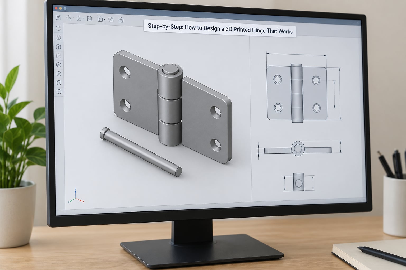
Work through these six stages in order. Each one feeds the next, and skipping the clearance stage is what turns a decent model into scrap filament.
Choose the hinge style and load direction
Pick the architecture before you model anything, because the load direction decides it. A pin-and-socket hinge (a printed cylinder in a printed hole, or a metal pin in a printed barrel) handles heavy loads and repeated cycling best, and it works in any orientation. A living hinge is a thin flexible section of wall with no separate parts at all, so it’s the right choice when you want a box lid with zero assembly and no hardware.
A print-in-place hinge prints both halves in one go, held apart by the same clearance gap, which saves assembly but always carries some slop. A friction or detent hinge is for lids that should hold an angle instead of flopping to the open or closed end.
Decide where the load actually goes before you draw anything. A lid that swings open against gravity loads the hinge mostly in tension as it reaches full extension, while a box flap hanging open loads the knuckles in shear. Tension and bending are what printed layers handle well; peeling layer lines apart is what kills a joint.
Set the barrel and pin clearances
Clearance is the whole game. Start with 0.2 to 0.3 mm total radial gap for a well-calibrated PLA or PETG machine. Going tighter invites a fused joint, and going looser guarantees visible wobble.
| Material | Pin-to-bore clearance | Notes |
|---|---|---|
| PLA | 0.20 to 0.30 mm | Tightest and stiffest; unforgiving of over-extrusion |
| PETG | 0.25 to 0.35 mm | Stringing can close the gap, so check the first layers |
| ABS / ASA | 0.25 to 0.35 mm | Warping near small bores makes slop appear after cooling |
| TPU | 0.30 to 0.40 mm | Soft material squeezes, so leave more room |
| Nylon | 0.20 to 0.30 mm | Absorbs moisture and swells slightly over days |
These numbers assume a machine that has passed a flow rate test. On a printer running 5 percent heavy, add about 0.1 mm. If your bore prints undersized because of an elephant foot on the first layer, that first-layer bore is the one that fuses, so you may need 0.3 mm rather than 0.2.
For the axial direction, leave about 0.1 to 0.2 mm of end float so the pin can seat without binding. If you use a metal pin, size the bore from the measured pin, not the nominal size on the packaging.
Add knuckle lengths and end stops
Distribute rotation across at least three knuckles on each leaf, interleaved, so load transfers between knuckles instead of bearing on one pair all cycle long. Five knuckles per leaf is better still and costs nothing but print time.
Keep knuckles roughly one to 1.5 times the pin diameter in length. Longer knuckles resist bending but then the leaves can collide with each other through the opening arc, which is the second most common hinge failure.
Add a physical end stop at the closed position. Two flat faces that meet at 90 degrees, or a small post that seats into a pocket, will define the closed angle far more predictably than relying on friction alone. It also gives the hinge somewhere to take its load at the limit, instead of stressing the last degree of rotation.
Strengthen the hinge body and pin connection
The pin connection is where hinges snap. If the pin is a separate piece, add a shoulder or a retaining collar so it cannot walk out axially under repeated load, and a generous fillet where the pin meets the leaf so the stress spreads instead of concentrating.
On the leaves themselves, use at least four perimeters, add gussets where the leaf meets the barrel, and avoid any internal corner sharper than roughly 0.5 mm. A sharp inside corner is a notch, and a notch is where a printed part will eventually crack.
Watch for one trap: reinforcement that touches the rotating partner. A gusset on one leaf that sweeps into the arc of the other leaf stops the hinge dead at about 60 degrees. Model the full rotation sweep before you add material, not after.
Orient the part for layer strength
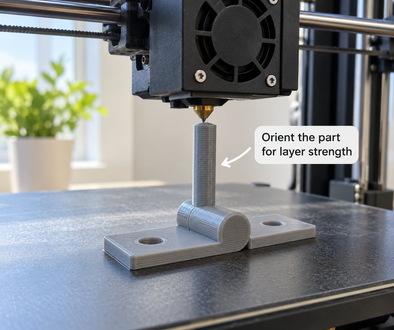
Orientation decides whether a joint survives. Printed layers bond strongly in tension and shear within a layer plane, and weakly between layers. So every load you can route within a layer plane is a load the material handles well.
For a pin-and-socket hinge, stand the pin axis vertical. The pin then prints as a column with strong layer bonding around its circumference, and the barrel bore prints as a clean vertical hole with predictable diameter. If the pin lies flat, the bore has to be a horizontal bridge, which sags and gives an oval, sloppy fit.
For a living hinge, print it flat in the XY plane so the fold line runs along the layer direction. A living hinge printed standing up in Z, with the fold running vertically through the layers, delaminates along the layer line after a few dozen cycles. If you must print it in Z, give it a long gentle radius on the outside and a short inner surface so the strain spreads along the filament rather than across it.
Leaves should sit flat whenever possible. A leaf standing on edge is strong but a leaf lying flat is stronger still, because bending a flat leaf forces the layers to stretch rather than peel.
Print a test coupon and validate the fit
Before committing a full print, preview the g-code layer by layer and confirm there is actual empty space where the hinge must move. If the preview shows material bridging the gap at some layer, that layer is where the joint will weld.
Then print a small coupon: a single barrel with a matching pin, 20 to 30 mm long, at the same orientation as the real part. Cycle it by hand a dozen times, then apply the load it will carry in service. Check for three things.
- Free motion. The pin should drop in by hand and swing without a hard stop. If it only moves in one direction, look for a misaligned bore or a leaf collision in the arc.
- No slop. If the pin visibly rocks, your bore printed oversize or your clearance is on the wrong side of the target. Measure it with calipers and adjust by tenths of a millimetre.
- Layer integrity. After cycling, look for whitening or micro-cracks at the fillet. Whitening that turns into a crack means the leaf is bending beyond what the layer bond can take, so add gussets or shorten the leaf.
Once the coupon behaves, scale the clearance proportionally for the real part. Small features shrink more than large ones relative to the nozzle, so a coupon at half scale needs a slightly larger gap than the full-size version.
Common Mistakes
Almost every failed hinge traces back to one of these, and each has a specific fix.
| Mistake | What you see | Fix |
|---|---|---|
| Zero or negative clearance | Joint is solid, hinge never moves | Open the gap to 0.2 to 0.3 mm and reprint |
| Over-extrusion | Gap closes at the first few layers only | Run a flow rate test, correct the multiplier |
| Elephant foot | Bottom of the bore fused, upper bore fine | Chamfer the bore entry or trim the skirt |
| Wrong orientation | Cracks along a layer line after cycling | Stand pin axes vertical, print living hinges flat |
| Leaves too short | Hinge stops at 60 to 90 degrees | Lengthen leaves or remove the interfering gusset |
| Sharp internal corner | Single crack line radiating from the fillet | Add a 0.5 mm radius or larger |
| Galling between identical plastics | Stiff after a few dozen cycles, squeaks | Fit a nylon bushing and add silicone grease |
| Pin walks out | Leaf collapses under load | Add a shoulder, collar or cross-pin |
A few habits help more than any single trick. Design the clearance around your printer’s worst layer rather than its best one. Pair materials instead of matching them, since two identical plastics rubbing in a bearing tends to micro-weld. And print the test coupon at full orientation even if you scale it down, because orientation changes the fit as much as clearance does.
Frequently Asked Questions
What clearance should I use for a 3D printed hinge pin?
On a calibrated FDM printer, 0.2 to 0.3 mm of radial gap between pin and bore works for PLA and PETG. Add roughly 0.1 mm if your extrusion multiplier runs heavy, or 0.1 mm more for TPU, which squeezes under load. If the joint fuses at the first layer only, the cause is usually an elephant foot rather than the modelled clearance, so chamfer the bore entry instead of loosening the whole fit.
Should a 3D printed hinge be printed vertically or horizontally?
For a pin-and-socket hinge, stand the pin axis vertical so the bore prints as a clean vertical hole rather than a sagging horizontal bridge. For a living hinge, print it flat in the XY plane with the fold line running along a layer, because a fold line that runs through the layer stack will delaminate after a modest number of cycles.
What is the best material for a durable 3D printed hinge?
PETG is the practical default for a hinge that flexes repeatedly, because it takes many more cycles before whitening and cracking than PLA. Nylon and ASA outlast it for heat and fatigue, and TPU is the only flexible option. PLA works fine for a pin-and-socket hinge that rotates instead of bending, and it prints more dimensionally accurate.
How do I stop a printed hinge pin from coming loose?
Give the pin a shoulder larger than the barrel bore so it cannot slide axially, or add a retaining collar at the far end. For a captive design, print the pin loose inside the barrel and let the knuckles trap it. If the pin is metal, drill a small cross-hole in the leaf and fit a wire pin through it.
How strong does a 3D printed hinge need to be?
Work out the real load first. For a handheld controller lid, the hinge carries little more than the weight of the lid itself at full extension. For a box flap left hanging open, the knuckles see pure shear. Print at four or more perimeters, add gussets where the leaf meets the barrel, and test to roughly twice your expected load on a coupon before trusting the full part.
Conclusion
Start with generous clearances. Give the pin and bore 0.2 to 0.3 mm of radial gap on a calibrated machine, then widen it if your extrusion runs heavy, and preview the g-code before you print to confirm the gap stays open at every layer.
Reinforce the pin connection with a shoulder or collar, fillet every corner that sees load, and route the load through the layer plane rather than across it by standing pin axes vertical and printing living hinges flat. Then print a small coupon at full orientation, cycle it a dozen times, measure the bore with calipers and adjust by tenths of a millimetre before committing filament to the real part.