Learning how to print functional gears that mesh comes down to two numbers you control in CAD: the module, which sets tooth size, and the backlash, which sets how much room the teeth have. Get those right and a 3D printed gear pair runs smoothly. Get them wrong and the mesh binds on the first turn or strips a tooth under load.
Most binding failures trace back to one assumption. CAD gear generators are built for machined metal with near-zero tolerance, but FDM and resin printing both add material where you did not want it, and extrusion perimeters bulge outward in the XY plane. A zero-backlash model is a jam waiting to happen.
How well do 3D printed gears hold up? For jigs, camera dollies, robot arms, actuator drives and prototype gearboxes, they hold up well when you design for clearance and print in a material that suits the load. For safety-critical mechanisms, high-speed spindles or anything where a snapped tooth injures someone, they are the wrong part.
This guide walks through the whole job: choosing the gear pair, modelling clearance, picking a material, slicing, printing, and then measuring the result before you commit to a full set.
Table of Contents
- 1What You Need
- 2Step-by-Step
- 3How to Print Functional Gears That Mesh
- 4Step 1: Define the Gear Pair and Intended Load
- 5Step 2: Model the Teeth with Working Clearance
- 6Step 3: Choose a Material and Printer
- 7Step 4: Export, Slice, and Choose the Print Orientation
- 8Step 5: Print, Measure, and Test the Mesh
- 9Common Mistakes
- 10Frequently Asked Questions
- 11What is the best filament for functional 3D-printed gears that must mesh?
- 12How much backlash should I use when 3D printing meshing gears?
- 13What layer height is best for accurate 3D-printed gear teeth?
- 14Can resin 3D-printed gears work for functional mechanisms?
- 15How do I make a 3D-printed gear fit securely on a shaft?
- 16Are 3D-printed gears strong enough for mechanical loads?
- 17Conclusion
What You Need
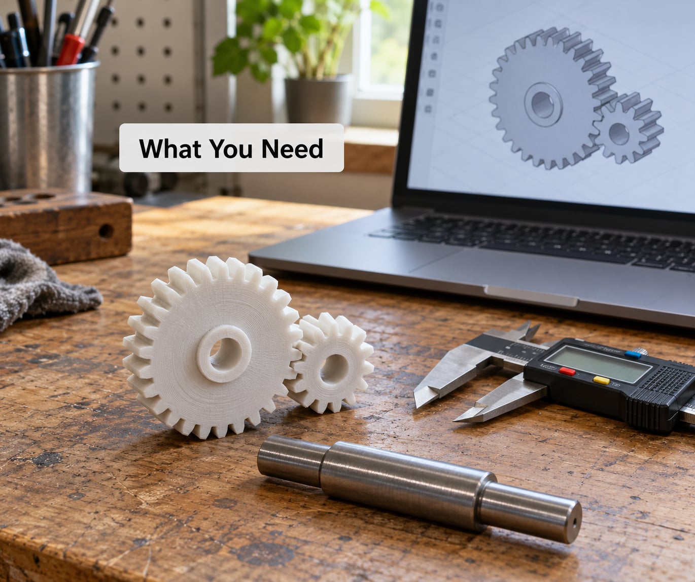
A working setup is small. The measuring tool matters more than people expect, because the whole method depends on comparing what you designed against what came off the bed.
- Parametric CAD with a gear generator. Fusion 360, FreeCAD with its gear workbench, or a browser-based generator such as OpenJsCad, evolventdesign or stlgears. Generate every gear in a set with the same tool so module and pressure angle cannot drift between parts.
- An FDM printer you know well, ideally with a CoreXY or cartesian bed and manual reference marks. Gantry-sag printers still make fine gears as long as the first layer is flat and you measure the result.
- A hardened steel nozzle for anything functional. A brass nozzle wears oval within a few hours of functional printing and quietly ruins tooth accuracy.
- Filament in the material you settled on, plus a small amount of scrap for calibration prints.
- Digital calipers for outside diameter and bore, and ideally a micrometer for tooth thickness, since caliper jaws span several teeth and average out the profile.
- A round shaft and a scrap bearing block to build a test fixture. A 8 mm steel rod, two printed bearing blocks and a small hand drill turn a set of gears into a test rig.
- The design parameters: module, tooth count, pressure angle, face width, target center distance and an intended backlash value.
Time for the whole process on a small two-gear test set is maybe two hours including print time. Scaling that to a six-gear planetary is a weekend, and most of that is printing.
Step-by-Step
How to Print Functional Gears That Mesh
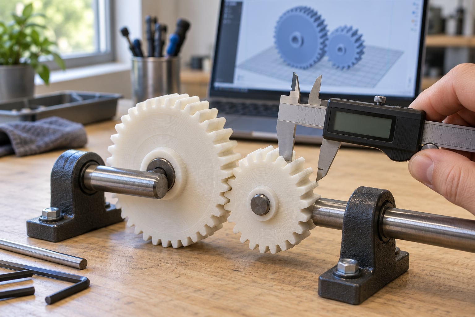
Print the pair, not one gear. Set backlash in the model, keep the first layer flat, measure the actual outside diameter and tooth thickness, then assemble on a straight shaft and turn it by hand before powering anything. The core print setup for meshing gears is orientation and dimensional checking, and the sequence below covers both.
Step 1: Define the Gear Pair and Intended Load
Start with the mechanism, not the gear. Write down the speed, the torque, the direction of rotation and whether the load is steady or shocky, because a gear that lifts a camera slider behaves nothing like one indexing a robotic arm.
Spur gears are the right default. They are easy to print, easy to model and quiet enough for most mechanisms. Helical gears run smoother and carry more load, but they need axial clearance along the shaft and more support work. Worm drives suit high reduction in a single stage, yet printed worms wear fast against a plastic or printed wheel. Bevel and hypoid gears need a whole change in your fixture, so skip them for a first functional build.
Pick the module from the printer. A 0.4 mm nozzle can hold module 0.8 and up comfortably, module 0.6 is the practical floor for clean teeth, and anything below that wants resin. Most hobby functional gears sit at module 1 to module 2.
Give the face width enough room to carry the torque. Face width is normally three to five times the circular pitch; for a module 2 gear that means roughly 19 to 31 mm, which is more plastic than most people print. Dropping to 8 to 12 mm on a slow, low-load mechanism is usually fine. A gear wider than roughly ten times its thickness deflects under load and stops meshing correctly.
Step 2: Model the Teeth with Working Clearance
Center distance is the number that makes or breaks a mesh, so set it before anything else. For two external gears with module m and tooth counts Z1 and Z2, the working value is:
C = m × (Z1 + Z2) / 2
Worked example: a 15-tooth and a 30-tooth pair at module 2. Pitch diameters are 30 mm and 60 mm, and center distance is 2 × (15 + 30) / 2 = 45 mm. Add your total backlash as extra center distance, roughly half the value per gear, so a 0.4 mm backlash moves the centers to about 45.2 mm. If your gearbox housing is fixed, design the housing to that number rather than forcing the gears to fit.
Involute profiles generate themselves in every gear generator worth using. The parameters you choose matter more than the tool.
| Module | Tooth count range | Starting backlash (0.4 mm nozzle) | Notes |
|---|---|---|---|
| 0.6 | 14+ | 0.15 to 0.20 mm | Resin territory on FDM |
| 0.8 | 14+ | 0.20 to 0.25 mm | Lower limit for reliable FDM teeth |
| 1.0 | 14+ | 0.25 to 0.30 mm | Comfortable on most printers |
| 1.25 to 1.5 | 12+ | 0.30 to 0.40 mm | Strong roots, forgiving of layer height |
| 2.0 | 12+ | 0.40 to 0.50 mm | Easiest to print, needs a firm bed or hub |
These are starting points, not truth. Print one gear from each pair, measure, and treat the difference between measured and designed size as your correction for the next iteration.
Pressure angle. 20 degrees is the standard and it is what most libraries default to. 25 degrees gives a stronger tooth root and resists undercutting, which is why it is the better choice for printed gears carrying real torque.
Tooth count and undercutting. Below about 14 teeth at a 20 degree pressure angle, the standard involute profile gets cut into near the root and the gear weakens there. Stay at 16 teeth or more, switch to 25 degrees, or apply a small positive profile shift.
Backlash. This is the gap between the non-driving flanks of two meshed teeth, and it is the clearance your printer eats. Zero backlash in CAD gives you a jammed pair. The table above gives starting points per module; back off from there if your printer over-extrudes.
Root fillet. Round the base of each tooth with a radius of roughly 0.3 to 0.5 times the module. Sharp internal corners are where layer lines create stress risers, and that is where printed teeth snap off.
Bore and hub. Design the shaft fit before you print. A D-shaped or double-D bore grips a round shaft with no creep, which solves the loose-gear problem better than any amount of print quality. Add a hub so the tooth roots carry load into the hub instead of the bore wall, and give the bore a lead-in chamfer so assembly does not chip the rim.
Step 3: Choose a Material and Printer
Material decides three things at once: how stiff the tooth is, how much heat it survives, and how accurately it holds its dimensions. FDM materials hold dimension well on XY surfaces and badly on tall vertical walls, which matters because tooth flanks in the flat orientation are vertical.
| Material | Approx. heat limit | Strength and wear | Dimensional accuracy | Best use |
|---|---|---|---|---|
| PLA | about 55 to 60 C | Stiff in tension, brittle, poor wear resistance | Excellent | Low-load jigs, fit tests, display gears |
| PETG | about 75 to 80 C | Tougher than PLA, creeps slowly under load | Very good | Camera dollies, blind actuators, general mechanisms |
| ABS | about 100 to 105 C | Good impact strength, needs an enclosure | Fair, warps without control | Warm environments and larger flat parts |
| ASA | about 100 C | Like ABS with far better UV stability | Fair, warps without control | Outdoor actuators and exposed gearboxes |
| Nylon (PA) | varies widely by grade | Excellent toughness, low friction, self-lubricating | Poor, absorbs moisture and creeps | Worm wheels, wear surfaces, repeated high load |
| Carbon-fibre nylon | varies by grade | Stiffest printed option, very strong per layer | Poor, hard on nozzles and feeders | Loaded gearbox carriers and hubs |
| Resin (MSLA) | varies by resin | Very stiff, brittle, wears fast against itself | Best available | Fine modules below 0.8 and precise fits |
For most functional builds I start with PETG and move up only when the mechanism runs warm or the teeth see real load. PLA is fine for anything you can turn by hand, and it deforms permanently once friction and motor heat push past its glass transition temperature, which is why PLA gears go round and round and start skipping.
Resin earns its place at fine module sizes where an FDM nozzle cannot resolve the tooth profile. It also gives you a bore so clean it needs no shimming. Handle it thoughtfully: resin is brittle, so keep face widths generous and avoid cantilevered roots.
Step 4: Export, Slice, and Choose the Print Orientation
Export as 3MF where your tool allows it, since it carries mesh units and can carry per-object settings, otherwise use STL and confirm your units are millimeters. Export the whole gear set from one assembly so you know nothing shifted between parts.
Orientation is the first real trade-off. Printed flat on the bed, teeth are strong because layer lines run across them rather than along the flank, and the part grips the bed; the cost is elephant’s foot on the first layer and stepped ridges on the flank, which acts like a file on the mating tooth. Printed on edge, the flanks are smooth and accurate but the tooth root is weak along the layer direction and the bore becomes elliptical. Flat wins for strength on low and medium loads. On edge wins for fine module and high precision, provided you keep face width wide.
| Setting | Cura | PrusaSlicer / OrcaSlicer | Value | Why it matters |
|---|---|---|---|---|
| Layer height | Layer Height | Layer height | 0.10 to 0.12 mm | The single biggest lever on tooth profile error |
| Wall thickness | Wall Line Count | Perimeters | 4 to 5 | More perimeters mean a stiffer, more accurate tooth |
| Infill | Infill Density | Infill density | 40 to 60 percent | Mostly for the hub, not the teeth |
| XY size compensation | Horizontal Expansion | XY size compensation | -0.05 to -0.15 mm | Perimeters bulge out and eat your backlash |
| Elephant’s foot | Initial layer horizontal expansion | Elephant foot compensation | 0.15 to 0.20 mm | Stops the flat-printed foot from lifting tooth height |
| Outer perimeter speed | Outer Wall Speed | External perimeters speed | 30 to 40 mm/s | Slower outer walls print tighter and truer in XY |
| Seam placement | Seam Position | Seam position | Rear or nearest to the bed | Keeps the start and stop of the extrusion off the tooth flanks |
| Printing speed | Print Speed | Printer max speed | 40 to 50 mm/s | Rushing shows up as corner accuracy loss |
Supports are usually unnecessary for spur gears lying flat, since the tooth flanks at 20 degrees angle stand without bridging trouble. A helical or worm gear standing on edge may need supports under the helix, and a print-in-place planetary needs supports inside the shaft cavity.
Step 5: Print, Measure, and Test the Mesh
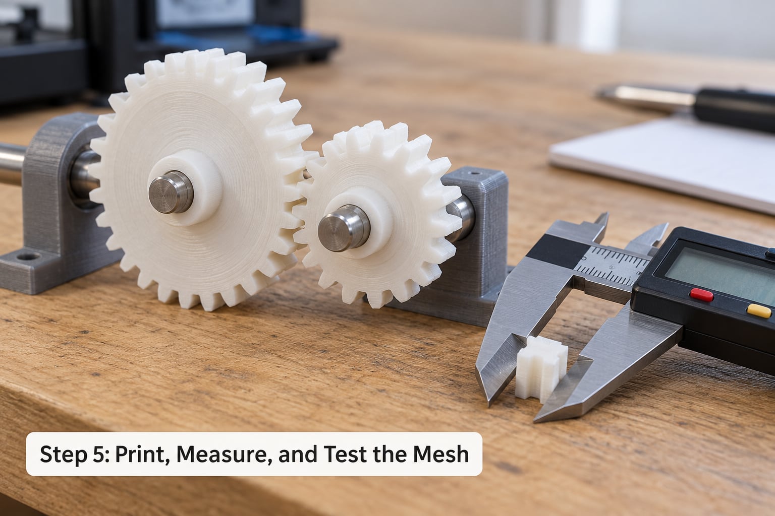
Remove supports, then measure before you fit anything together. Check the outside diameter at three points around the gear and compare against your designed pitch diameter plus the tooth head allowance. Measure tooth thickness across a single tooth with a micrometer if you have one, since caliper jaws average across several.
Look at the teeth under direct light. Ringing ripples on the flank mean the outer speed is too high. A step where the layer lines break on the flank means the seam landed there, and that is the spot that eats the mating tooth over time. A visible lip around the base means elephant’s foot compensation is set too low.
Then build the fixture. Press or clamp both gears onto a straight shaft at your designed center distance, with a bearing block each side, and turn the pair by hand. It should rotate through a full revolution with light, even resistance and no point of binding. That even resistance is the real test of backlash, because a gear with too much slop feels uneven and a gear with too little binds at one tooth.
Change one variable per iteration. Add 0.05 mm of backlash and reprint only the pair, not a whole gearbox. Once the pair runs clean by hand, add a small motor at low speed, then run it for ten minutes and recheck the mesh, because thermal growth and layer relaxation both show up under load.
Common Mistakes
Almost every gear problem shows up as one of five symptoms, and each has a cause you can measure rather than guess at.
| Symptom | Root cause | Fix |
|---|---|---|
| Gears will not turn at all | Backlash too small once the printed tooth bulges, or centers too close | Add 0.1 mm backlash and lengthen center distance by half that amount |
| Rotates but rattles with a knock | Too much backlash, or center distance too long | Remove 0.05 to 0.1 mm of backlash and re-measure |
| Tooth snaps off at the root | Low layer height with low infill, sharp root corners, or PLA creeping under heat | Add a root fillet of 0.3 to 0.5 module, raise perimeters and infill, move to PETG or nylon |
| Noise and rapid wear of one flank | Z-seam or ringing on the tooth surface acting as a file | Move the seam, drop outer perimeter speed, tighten XY compensation |
| One gear works loose over time | Round bore on a round shaft creeps, or elephant’s foot lifted the bore | Use a D-shaped bore, add a clamp or setscrew, or press in a heat-set insert |
| Two gears from the same file do not match | Print settings drifted between runs | Print the pair on the same plate with identical settings, and set XY compensation once |
| Gear turns but feels rough through the whole revolution | Layer height too coarse or part too cold causing under-extrusion | Drop to 0.12 mm layers and check nozzle temperature against the filament |
A few habits prevent most of that. Keep every gear in a set generated by the same tool with the same pressure angle. Print pairs on the same plate. Measure a calibration gear before each filament change rather than after a failure. And run the mechanism at low speed first, because printed teeth need a few minutes of running to settle into each other.
Know where to stop. Printed gears are a bad choice for safety-critical linkages, for anything spinning at high RPM where a balance error causes vibration, and for precision positioning where backlash shows up as positional error. If the failure of that part injures someone, machine it or buy it.
Frequently Asked Questions
What is the best filament for functional 3D-printed gears that must mesh?
PETG is the best all-round choice for functional 3D-printed gears. It holds dimension tightly, tolerates impact better than PLA and stays rigid well past the warmth a small gearbox motor produces. Use PLA only for low-load mechanisms you turn by hand, ASA or ABS where heat matters, and nylon or carbon-fibre nylon for wear surfaces and repeated load. Match the material to the temperature at the teeth, not to the rest of the build.
How much backlash should I use when 3D printing meshing gears?
For a 0.4 mm nozzle FDM printer, start at 0.2 to 0.3 mm for module 1, 0.3 to 0.4 mm for module 1.25 to 1.5, and 0.4 to 0.5 mm for module 2. Resin needs far less, often 0.05 to 0.1 mm. Add that backlash to your center distance and print a test pair, because over-extrusion and elephant’s foot will eat into any value you pick.
What layer height is best for accurate 3D-printed gear teeth?
Use 0.10 to 0.12 mm layer height for gear work. That puts three to four layers across the smallest tooth feature on a typical module 1 gear, which is what keeps the flank from looking like a staircase. Module 2 and larger gears print fine at 0.16 to 0.2 mm. Anything above 0.2 mm starts to distort the profile enough that the gear binds or runs rough.
Can resin 3D-printed gears work for functional mechanisms?
Yes, and resin wins where FDM struggles. An MSLA print resolves fine modules below 0.8 and produces a bore precise enough to press onto a shaft with no shimming. The trade-off is brittleness and poor surface wear, so resin gears suit slow, low-load, low-cycle mechanisms rather than anything that grinds continuously. Keep face widths generous and support the tooth roots.
How do I make a 3D-printed gear fit securely on a shaft?
Print a D-shaped or double-D bore matching a round shaft. The flats prevent rotation and creep far better than a round hole on a round shaft. For higher torque, add a clamping hub, a cross pin or a radial setscrew through the web. A heat-set brass insert works well in nylon and PETG, though it needs a larger bore and careful hole sizing to avoid splitting the hub.
Are 3D-printed gears strong enough for mechanical loads?
They are strong enough for jigs, camera dollies, robotic arms, blind actuators and prototype gearboxes when you design for it: a root fillet of 0.3 to 0.5 module, four or five perimeters, a proper hub carrying load into the bore, and a material chosen for the working temperature. They are not strong enough for safety-critical linkages, high-RPM shafts or precision positioning. Tooth load is limited by bending, not compressive strength.
Conclusion
Start small. Model a correctly spaced pair at your chosen module, give it real backlash, print both gears on the same plate, then measure the outside diameter and tooth thickness before fitting them together. Adjust one variable at a time until the pair turns evenly by hand, and only then scale up to the full mechanism.
Mastering how to print functional gears that mesh is mostly tolerance work rather than printer work. The gear that works is the one where clearance was designed in from the start and confirmed with calipers after printing.