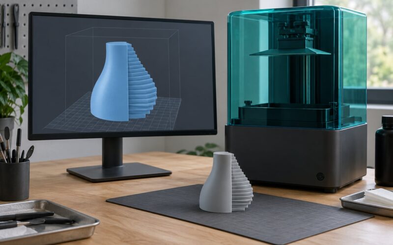
A hollow resin print suction cup failure is a trapped-pressure problem, not a speed problem. Air and liquid resin seal themselves inside a closed cavity, and every peel has to work against that vacuum until the supports tear, the layers split, or the part leaves the plate entirely. The fix runs in a fixed order: vent the geometry, kill the wide flat cross-section, thicken the transitions, then slow the peel and check the material.
Most people start at the wrong end. They drop lift speed from 100 mm/s to 60 mm/s, lose an hour, and the part still tears at the same layer. The numbers matter, but geometry comes first, because a sealed cavity will always fight you no matter how gentle the peel is.
Before you touch the slicer, here is the short version in six steps. This is the order I would work through it.
- Find out at which layer the part failed and what the failure looked like.
- Punch at least two drain holes, 3 mm minimum, one on the build plate side and one on the face pointing away from the plate.
- Make sure the holes are reachable early in the print, not only near the top of the model.
- Raise hollow wall thickness to 3 mm minimum and soften any sudden solid-to-hollow transition.
- Tilt the part 20 to 45 degrees off the plate so no single layer is a wide flat slab.
- Slow the peel to roughly 100 mm/s lift and 150 mm/s retract, enable slow lift for the first five layers, and warm the resin to 25-30 C.
If the part printed cleanly and then failed the vacuum test, the problem is somewhere else entirely, and it is usually the rim or the surface rather than the cavity. That distinction saves a lot of wasted resin.
Table of Contents
- 1What You Need
- 2Step-by-Step
- 3Diagnose hollow resin print suction cup failures
- 4Redesign the model and control trapped air
- 5Fix material, adhesion, and curing problems
- 6Improve the sealing and test surface
- 7Verify the repair and prevent repeat failures
- 8Common Mistakes
- 9Frequently Asked Questions
- 10How big should drain holes be on a hollow resin print?
- 11Is my print failure a suction cup problem or a bad FEP adhesion problem?
- 12Should you hollow out resin prints at all?
- 13How do I cure the inside of a hollow resin print that already failed?
- 14Does resin temperature really affect suction cup failures?
- 15Conclusion
What You Need
Gather this before you start, so you are not stopping mid-diagnosis to hunt for a bottle of isopropyl alcohol with uncured resin on your hands.
- The failed part. Keep it exactly as it came off the plate. If you rinse it immediately you destroy the evidence of where the leak was, because the wet resin tells you where the cavity was open.
- A bright light source. A phone flashlight held against the inside of the shell finds pinholes and thin spots that look solid in daylight.
- 99% isopropyl alcohol, nitrile gloves, paper towels and a stiff brush. The gloves are not optional when handling uncured resin, and the brush is what gets resin out of a narrow internal cavity.
- Digital calipers. You are checking wall thickness and hole diameter, and eyeballing both of those at 3 mm is guesswork.
- The source file and your slicer. ChiTuBox, Lychee, PrusaSlicer and Formlabs PreForm all have island and cup detection plus automatic hole punching. The layer view is how you find the exact layer that failed.
- A vacuum gauge. A hand vacuum pump with a dial gauge, or a vacuum cup tester, turns a fuzzy impression into a number you can compare before and after a fix.
- A thermometer for the resin. Cold resin is one of the most commonly missed causes, and you cannot feel a 5 degree difference reliably.
- Build plate film and a spare plate. If the film is stretched, cloudy or dented, you need to know that before you start blaming the model.
Work in a ventilated area and never cure a part that still holds liquid resin without gloves on. Hollow shells are full of uncured resin that has been sitting against the walls for hours.
Step-by-Step
Diagnose hollow resin print suction cup failures
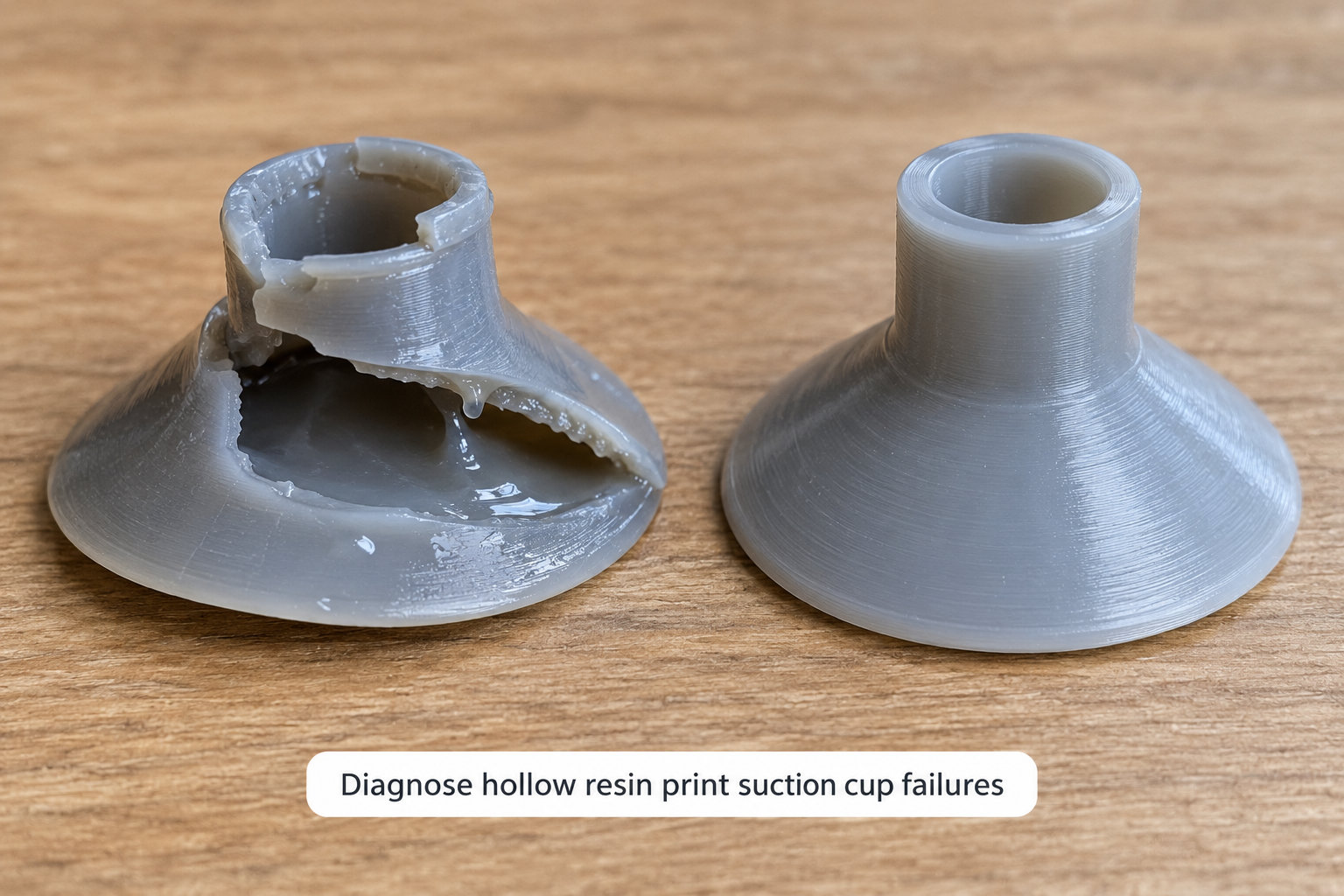
Start by identifying the failure type, because each one points at a different root cause. The part tells you which one you have if you know what to look for.
The mechanism is worth understanding in one paragraph. Each layer separation is a peel event, and peel force scales with the cross-sectional area of the layer being pulled and inversely with how stiff that fresh layer still is. A sealed hollow cavity cannot equalise pressure, and the liquid resin inside behaves like a piston seal, so every peel also has to work against the trapped volume. A larger cavity, colder resin and a faster peel all make the same print worse, which is why a model that survives 20 layers can tear at layer 200.
Some geometry is inherently risky. Handles with an enclosed hole, slots that close into a loop, enclosed domes, helmets and masks, hollow rings and any large cross-section lying flat on the plate all create either a sealed chamber or a pressure spike. If your part has one of these and it is not vented, treat a suction cup failure as expected rather than unlucky.
| What you see | Most likely cause | First thing to change |
|---|---|---|
| Supports tear away and the model separates at one layer, plate stays clean | Trapped vacuum in a closed cavity | Add early, correctly sized drain holes |
| Whole part launches off the plate mid-print | Large flat cross-section plus a sealed cavity | Tilt the part 20-45 degrees off the plate |
| Print splits at the solid-to-hollow transition | Too few layers of wall thickness carrying the load | Raise wall thickness to 3 mm minimum |
| Part stays put but layers shift and the wall delaminates | Under-cured normal exposure time | Increase normal exposure, not just bottom exposure |
| Print holds the plate only by a thin film edge, or a raft shears off | Weak FEP adhesion or an unlevel plate | Level and re-film the plate, not the model |
| Print looks fine, prints fine, then fails the vacuum test | Rim flatness or surface contamination | Inspect the rim, then the test surface |
Next, find the failure layer in your slicer. The torn or split line on the part maps to a layer number, and that layer is where the cavity closed or where the cross-section got wide. This is the single most persuasive piece of evidence you can gather, and responders on r/resinprinting will ask for it before they will suggest anything else.
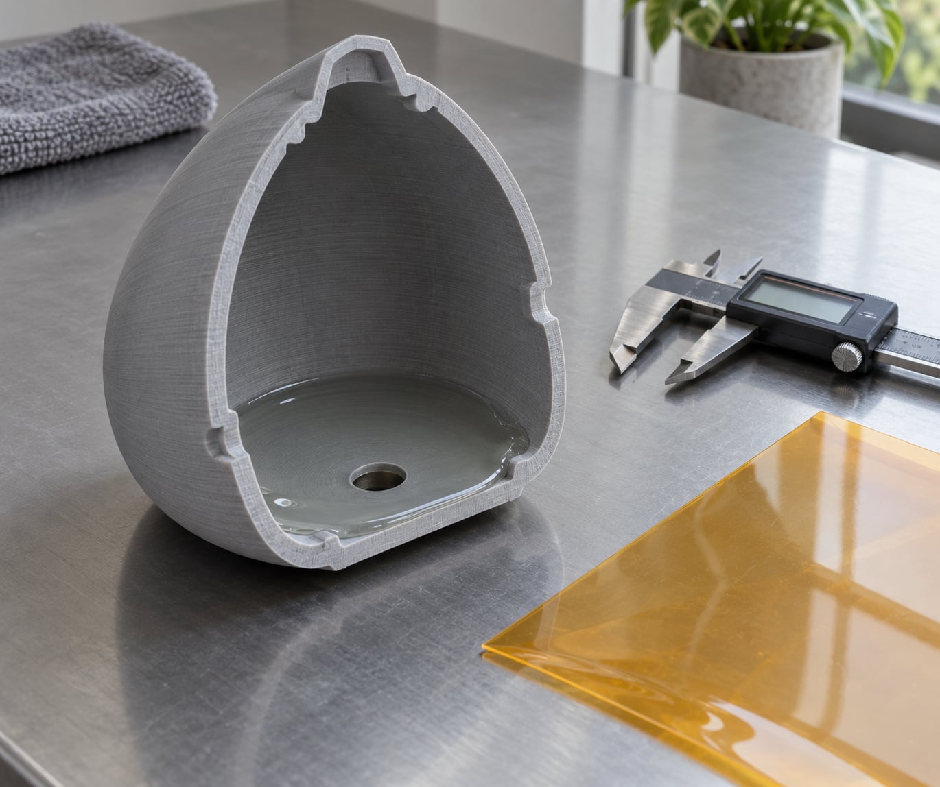
Then check the cavity itself. Shine the flashlight through the shell and look for thin spots, and check whether liquid resin is still sitting inside. If there is resin pooled in the bottom of the cavity when you look into the drain hole, that cavity never equalised and the pressure spike was live for the whole print.
Finally, look at the rim. Nicks, burrs, lifted edges and a lip printed at a slight angle all let air in under a test rig even when the cavity geometry is perfect. A rim that is not flat is a sealing problem, not a suction cup problem.
Redesign the model and control trapped air
Venting the cavity is the actual fix. Sizing and placement both matter, and most people get one of the two right.
On size, treat 3 mm as the floor, not the target. Small holes of around 2 mm are the most common mistake reported in print forums, and users consistently judge them as insufficient. One poster on r/3Dprinting sized a drain hole close to 1 cm so liquid could flow in and out freely, then filled and shook the part to confirm it drained. That is not wrong advice for a large cavity, it is just a bigger part.
On placement, use at least two holes. One goes on the build plate side, where it vents the cavity as it closes against the film. The other goes on the face pointing away from the plate, so trapped resin drains out once the part lifts clear. A single hole on the bottom leaves the cavity sealed for most of the print, which is why the part still splits at the solid-to-hollow transition even though you did add drainage.
Placement also has a timing rule. The holes must be reachable early. If the cavity is a closed loop of legs and the only opening sits at the very top of the model, everything below it prints as one giant suction cup for hundreds of layers. A poster described exactly this with a figure whose legs became a single sealed chamber until the holes were reached, which is why the failure appeared at layer 40 rather than layer 5.
Keep the holes off structural and cosmetic features. A hole through a thin rib, a mating face or an embossed detail weakens the part permanently, and a hole where a support attaches removes the support’s anchor. Rounded cutters also leave a cleaner edge than an extruded hole in most slicers.
Wall thickness is the second geometry fix. Use 3 mm as the minimum for a hollow shell, and keep that thickness consistent. The common failure is a solid section that thins abruptly into a hollow section, because the solid-to-hollow transition has to carry peel force through a thinner cross-section than the rest of the model. A gradual taper across a short distance spreads that load instead of concentrating it on one layer.
Orientation is the third. A wide part printed flat on the plate creates a large cross-section in a single layer, and the pressure spike that produces is only partly offset by venting. Tilting the part 20 to 45 degrees, and splitting a very large flat area into smaller towers, removes most of the problem before any vent hole is relevant. Flat-on-the-bed is the single most repeated cause in forum reports of hollow parts that turned into suction cups.
Finally, use the tools your slicer already has. ChiTuBox and Lychee can punch holes automatically and flag suspect cavities, and PreForm has its own cup detection. Running the detector before you print turns a guess into a check, which is why people on r/resinprinting are told to run it first rather than after another failed plate of resin.
Fix material, adhesion, and curing problems
Once the geometry is right, the material decides whether the part survives the peel. Three variables matter most.
Resin temperature comes first. Cold resin is thicker, and thicker resin means a higher peel force and a slower return flow through the hole, so the pressure spike lasts longer. Warm the resin to 25-30 C before you print and keep it there through the job. This is the least commonly checked setting in the whole process and one of the cheapest things to correct.
Viscosity is the same problem expressed differently. Resin above roughly 600 cP raises peel force noticeably, and cold resin pushes a normal bottle well past that point. Stir or roll the bottle for a full minute, scrape the bottom, and check the date. Signs of bad resin are cloudy colour, a strong or chemical smell, lumps that do not dissolve, and a vat that will not clear after a test print.
Exposure time decides whether the part can take the load at all. Under-cured normal layers give up first, because the wall is still soft when the plate tries to pull it away. If the split line looks clean and the surface feels chalky or rubbery, raise normal exposure time rather than only bottom exposure. Bottom exposure protects the first layers; normal exposure is what holds the wall together two hundred layers up.
Peel settings come next. Around 100 mm/s lift and 150 mm/s retract is a reasonable baseline for a hollow part, and slow lift for the first five layers protects the delicate base before the part has any strength. Lift distance matters too, because the plate has to travel far enough for a hollow cup to clear its own cavity before it moves sideways.
Wash and cure close the loop. Rinse in 99% isopropyl alcohol, then make sure light reaches the inside of the shell, not just the outside. A hollow part that is cured on the outside and left soft on the inside will pass a vacuum test and then crack the first time it is handled.
Supports are the part that actually tears first, so treat them as part of the fix rather than scaffolding around it. Use a support tip diameter of roughly 0.6 to 1 mm, add support bridges under overhangs that carry load, and increase the support count on a hollowed model because the walls are thinner than the solid model you sized the supports for. A raft is worth adding on a wide part for the same reason the orientation fix matters: more material joining the part to the plate means more peel force has to travel through the supports.
Here is the snapshot to work from. These are starting values for a hollow part, not absolutes, and they are the numbers worth returning to when you change one thing at a time.
| Setting | Starting point for a hollow part | What it changes |
|---|---|---|
| Lift speed | 100 mm/s | Peel rate, and how long trapped pressure has to equalise |
| Retract speed | 150 mm/s | How fast the part is pulled clear of the film once lifting |
| Lift distance | Enough for the cup to clear its own cavity | Prevents sideways drag while the cavity is still sealed |
| Slow lift | First 5 layers | Protects the base before the part has any strength |
| Resin temperature | 25-30 C | Viscosity, and with it peel force |
| Wall thickness | 3 mm minimum | How many layers carry the peel load |
| Drain hole diameter | 3 mm or larger, two holes | How fast the cavity can equalise |
| Support tip | 0.6-1 mm | How much peel force the support survives |
| Orientation tilt | 20-45 degrees off the plate | Cross-section area of the heaviest layer |
Check this table against the one real number you can measure: the layer at which the part failed. If the failure layer sits right after the holes open, venting is the answer. If it sits where the cross-section suddenly widens, orientation is the answer. If it sits hundreds of layers up with no geometry event, suspect the resin and the exposure instead.
Improve the sealing and test surface
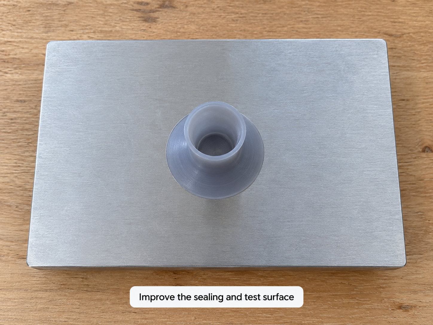
A cup that prints perfectly and still will not hold suction has a sealing problem. That is good news, because it is a five-minute fix instead of a reprint.
Inspect the rim under a light. Look for burrs, lifted edges from over-curing, a lip that is slightly conical, and any part of the rim that is not in one plane. A rim that varies in height by more than a fraction of a millimetre will bridge in the middle and leak at the edges. If the rim printed against the film it will be flatter than one that printed at an angle, which is a reason to prefer a print orientation where the rim is not the bottom face.
Then check the test surface. It needs to be flat, rigid, and clean of silicone oils and release agents, which is why a fresh sheet of acrylic or glass beats a used bench surface. A flexing surface looks like a leak that comes and goes with the pump stroke, and it is a different fault entirely from a trapped vacuum.
Level the build plate while you are there. A plate that rocks under light pressure is a plate that will print a rim with a high spot, and a high spot is a leak path. Clean the film, check the tension, and confirm the film is not cloudy or dented. This is the part of the job that also rules out the failures that only look like suction cup problems.
Verify the repair and prevent repeat failures
Test the same way every time, or the numbers mean nothing. Attach the vacuum gauge, pull to a defined pressure, and hold for 30 seconds. Repeat three times and record the reading each time. Before and after comparisons are only meaningful when the pump, the surface and the hold time are identical.
Run a short confirmation print rather than the full model. Print the first 40 layers, which is usually long enough to show whether a cavity is going to seal, and stop. If those layers come off cleanly the geometry is fixed, and you have saved a full night’s resin instead of discovering the problem at layer 300.
Keep a small log with the file, resin batch, resin temperature, wall thickness, hole diameter, orientation angle, and the lift and retract speeds. Suction cup problems are geometry and material problems, and both drift slowly enough that you will not remember last month’s settings without writing them down.
Common Mistakes
These are the errors I see repeated, and each one sends people down the wrong path.
- Dropping peel speed first. Slower peeling reduces the symptom and hides the cause. The cavity is still sealed, and the part fails later in the print or at a bigger size. Fix the geometry first, then tune speed.
- Using 2 mm holes. Too small for the resin viscosity and the cavity volume. Go to 3 mm minimum and larger for big shells.
- Relying on a bottom hole only. One hole on the plate side leaves the cavity sealed during most of the print. Add a second hole on the face pointing away from the plate.
- Putting the only hole near the top of the model. Everything below it prints as one sealed chamber. Holes need to be reachable within the first tens of layers.
- Cutting holes through ribs, mating faces or support anchors. The cup holds, and the part is now structurally weaker where it matters. Move the hole or thicken the feature.
- Filling the cavity with infill instead of venting it. Infill adds solid material to fight the peel with and does nothing to equalise pressure. A hollow shell with open vents does.
- Ignoring resin temperature. Cold resin is thick resin, and thick resin raises peel force. Warm it to 25-30 C.
- Chasing a failure that is not a suction cup. Unlevel plates, worn film, expired resin, under-exposure and Z-drift all look similar from the outside. Confirm the cavity was the cause before you rebuild the model.
Before the next print, run this short check. Every item is fast, and each one has ended a failure for me that a settings change alone did not.
- Two drain holes minimum, 3 mm or larger, one on the plate side and one on the far face.
- Both holes reachable early in the print.
- Wall thickness at 3 mm minimum, with a gradual solid-to-hollow transition.
- Part tilted 20 to 45 degrees, not lying flat.
- Resin at 25-30 C, mixed, and inside its shelf life.
- Lift around 100 mm/s, retract around 150 mm/s, slow lift for the first five layers.
- Plate leveled, film clean, tension even.
- Slicer cup detection run, in case you missed a cavity.
Frequently Asked Questions
How big should drain holes be on a hollow resin print?
Treat 3 mm as the minimum and go larger for bigger cavities. A 2 mm hole is the most common mistake and users regularly report it as too small once the resin is cold and thick. For a large shell, 4 to 6 mm per hole is safer, and forum users have had good results with holes near 1 cm that let liquid flow in and out. Use at least two: one on the build plate side and one on the face pointing away from the plate.
Is my print failure a suction cup problem or a bad FEP adhesion problem?
If the supports tear and the plate stays clean, it is trapped vacuum in a closed cavity. If the part only barely hangs on, a raft shears away, or a thin film edge is holding it, that is adhesion. A split at the solid-to-hollow transition is usually wall thickness. A clean shift with good plate contact points to under-exposure or Z-drift. If the part prints and only fails the vacuum test, look at the rim and the test surface instead.
Should you hollow out resin prints at all?
Usually yes, because solid resin is heavy, expensive and slow to cure, and a hollow shell prints faster with far less material. The catch is that hollowing only stays safe when the cavity is vented and the walls are at least 3 mm thick. Unvented hollowing is what creates suction cup failures. If you are not confident you can place the holes correctly, printing solid for the first layers and hollowing above them avoids the problem entirely.
How do I cure the inside of a hollow resin print that already failed?
Drain first. Rinse with 99% isopropyl alcohol, shake and tilt the part until the cavity stops running, and brush out what stays behind with a stiff bottle brush. Let it dry fully, because trapped solvent softens cured resin. Then cure it with UV light that reaches inside, turning the part so every internal wall gets equal exposure, and finish with a wash and cure cycle if you have one. Wear gloves, because failed hollow shells often still hold liquid resin.
Does resin temperature really affect suction cup failures?
Yes, more than most people expect. Cold resin is thicker, and thicker resin means a higher peel force plus slower flow back through the drain hole, so the pressure spike inside the cavity lasts longer. Viscosity above roughly 600 cP is a common warning sign. Warming the resin to 25-30 C before printing and keeping it there through the job is a cheap change that removes one of the three biggest contributors to peel force.
Conclusion
Start by identifying the failure mode rather than the setting. Inspect the failed part, find the layer it gave up on, and decide whether the cavity was sealed, the walls were too thin, the peel was too fast, or the rim was never flat. Then fix the geometry first, because two well-placed 3 mm holes and a tilted orientation solve more failures than any amount of speed reduction. Change one variable at a time, retest the seal with the same pump and the same 30 second hold, and keep the numbers in a log so the next part prints right the first time.