How to choose filament for mechanical parts comes down to the failure you are designing against, not the biggest tensile number on the spool. Match the load, service temperature and tolerance to the material, then confirm your printer can actually run it: PETG for everyday load-bearing parts, ABS or ASA for heat and UV, and nylon, PC or carbon-fibre composites for the demanding work.
Most brackets, jigs and housings never need an exotic engineering spool. What they need is a material whose weaknesses match the loads, printed in an orientation that puts the load through the walls rather than the layer lines.
Table of Contents
- 1What You Need to Choose Filament for Mechanical Parts
- 2Step-by-Step: How to Choose Filament for Mechanical Parts
- 31. Identify the mechanical loads and failure risks
- 42. Set the required temperature and dimensional tolerances
- 53. Compare filament families by strength and stiffness
- 64. Check layer adhesion, moisture sensitivity, and printability
- 75. Match the filament to the printer and application
- 86. Test a representative coupon before the final part
- 97. Validate the finished part under real conditions
- 10Common Mechanical-Filament Mistakes
- 11Frequently Asked Questions
- 12Is PLA or PETG better for mechanical parts?
- 13What is the best filament for mechanical parts?
- 14What filament should I use for automotive or under-hood parts?
- 15Do I need a hardened nozzle for carbon fiber filament?
- 16How long does nylon filament need to dry before printing?
- 17Why do my 3D printed parts break along the layer lines?
- 18Conclusion
What You Need to Choose Filament for Mechanical Parts
Before any material comparison, write the part down on paper. A one-page requirement sheet removes almost every bad filament decision I have seen people make, because the failure always comes back to the same four numbers that nobody recorded.
Gather these five things:
- The load case. Static compression, cyclic or fatigue, a sharp impact, sliding wear, sustained heat, or flexing back and forth. A part that only ever carries a bolt in tension is a very different problem from a lever that gets yanked once a week.
- The environment. Minimum and maximum service temperature, sunlight, chemicals, oil, and whether the part lives inside a machine, under a car, or on a fence post.
- The tolerances. How tight a bore has to be, whether it mates with a printed part or a bought bearing, and how much of that fit you can machine away afterwards.
- Your printer’s actual limits. Maximum nozzle temperature, whether the chamber is enclosed, whether it has a heated chamber, and whether you have a hardened steel nozzle and a way to dry filament.
- Filament data you can check. The manufacturer’s datasheet, the diameter tolerance and roundness spec, and whether the spool carries a batch or lot number you can trace.
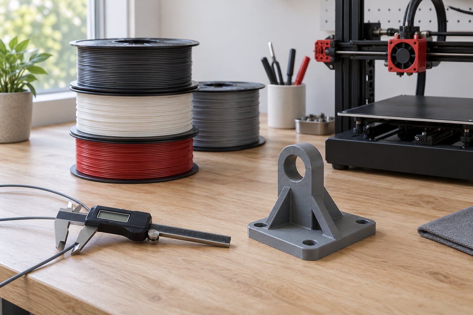
You also want a digital caliper and a way to load the part. A cheap bench vise and a set of weights will tell you more than any datasheet.
Two things worth adding if you will do this regularly: a filament diameter micrometer, which is a different measurement from the cheap calipers most people reach for, and a dry box. Both cost less than one wasted engineering print.
Write the failing force down, not just the part name. “Bracket for a monitor arm” means nothing; “carries 4 kg static, cycles through 5000 arm movements a year, sits at 45 °C near a window” tells you the material family immediately.
Step-by-Step: How to Choose Filament for Mechanical Parts
1. Identify the mechanical loads and failure risks
Mechanical parts fail in predictable ways, and each failure points at a different material property. Static compressive loading rewards stiffness and compressive strength. Cyclic or fatigue loading punishes anything that cracks easily and rewards materials with good fatigue resistance. Sharp impacts reward toughness, not tensile strength. A part under constant load fails by creeping, which is a completely different problem from a part under shock.
Decide which failure would make the part unsafe or simply unusable, then choose against that. A hinge that breaks once is a toughness problem. A bracket that sags a few millimetres under a constant load is a creep problem, and creep is exactly where PLA falls apart: it deforms permanently under sustained stress well below its stated strength.
Other failure modes worth naming: abrasion and wear on sliding surfaces, creep under sustained load, UV embrittlement outdoors, and chemical attack from fuels, oils or cleaners. A single part can combine two of them, and the tougher option often wins the combination. Friction matters too: a bushing running against a printed shaft wants a low-friction pairing such as nylon against TPU rather than two stiff plastics rubbing together.
Fatigue deserves its own note, because it catches people out. A material can be strong in a single pull and still fail after thousands of gentle cycles well below its strength limit. Unfilled nylon and polycarbonate are generally better choices for repeated loading than a carbon-filled composite, and if the cycles are genuinely severe, treat it as a design problem and add radius at the stress concentration rather than shopping for a stronger spool.
Community users on model-making forums put it plainly: carbon-fibre parts have poor layer adhesion and are bad at small detail, great for tensile strength unless you need flex. That is the trade in one sentence.
One practical rule I use: if the part is meant to fail, it should fail visibly and slowly rather than suddenly and without warning. That usually points to a ductile material with a long yield phase rather than a stiff composite.
2. Set the required temperature and dimensional tolerances
Heat deflection temperature, often called HDT, is the number that matters for mechanical duty. It is the temperature at which a loaded specimen deflects by a set amount under a defined load, and it is always lower than the material’s melting point. Glass transition temperature is a different thing entirely: it marks where the polymer softens, and it tells you more about dimensional stability than about strength.
As a rough guide, PLA loses stiffness around 55 to 60 °C, PETG holds to roughly 70 to 80 °C, ABS and ASA reach around 90 to 105 °C, nylon climbs past 150 °C, and polycarbonate sits somewhere between 110 and 130 °C depending on grade and print quality.
For tolerances, assume the printed part is a starting point, not a finished feature. Wall thickness, material shrinkage and thermal contraction stack together, and shrinkage alone differs between materials enough that a bore printed in one resin and another will not be interchangeable.
Design bearing fits oversized and finish them by hand. A printed hole is usually a little oval and always a little rough, and a hole-sink tool or a reamer turns a sloppy bore into a proper one in under a minute.
Shrinkage differs enough between materials that a bore printed in one resin will not drop into the same nominal bore in another. Polyamides and composites shrink more than PLA once they cool past their crystallisation point, and fibre-reinforced grades shrink anisotropically because the fibres resist contraction in one direction only. Print a test block with the bore in it, measure it cold with the caliper, and use that number as your design offset rather than the slicer’s nominal value.
Set your own tolerance expectations per axis. In the XY plane, most well-tuned printers hold features within about 0.1 to 0.2 mm, which is enough for a sliding fit with clearance. In Z, expect the layer height plus any swelling, so a 0.2 mm layer already puts a whole layer of slop between two mating faces. Parts that must be flat and parallel usually need those faces printed separately and joined, or machined afterwards.
3. Compare filament families by strength and stiffness
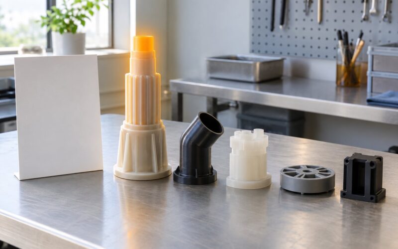
Comparing filament families is where people get stuck, so here is the short version. PLA is stiff and precise but brittle and heat-sensitive. PETG is tougher and more forgiving, with better layer adhesion and a usable temperature ceiling, which is why it became the default functional material for a reason. ABS and ASA add heat and UV resistance at the cost of warping and fumes. TPU handles flex and abrasion. Nylons and polycarbonate are the engineering tier, and the carbon-fibre composites on top of them trade toughness for stiffness.
The table below gives indicative properties. Treat them as starting points for comparison and check the manufacturer’s datasheet for the specific spool you buy.
| Material | Tensile strength (MPa) | Toughness | HDT (°C) | Stiffness | Moisture | Enclosure | Nozzle range (°C) |
|---|---|---|---|---|---|---|---|
| PLA / PLA+ | 45–60 | Low, brittle | 55–60 | High for PLA | Low | No | 195–220 |
| PETG | 45–55 | Medium–high | 70–80 | Medium | Moderate | No | 225–250 |
| ABS | 35–45 | Medium | 90–100 | Medium | Moderate | Strongly advised | 235–265 |
| ASA | 35–45 | Medium | 90–105 | Medium | Moderate | Strongly advised | 240–270 |
| TPU 95A | 30–45 | Very high | Below 80 | Low, flexible | Low | No | 220–245 |
| Nylon PA6 | 60–85 | High | 150–180 | Medium | High, needs drying | Yes | 250–280 |
| Nylon PA12 | 55–75 | High | 140–160 | Medium–low | Low–moderate | Yes | 250–280 |
| Polycarbonate | 55–65 | High, best Z bond | 110–130 | Medium | Moderate | Yes, heated helps | 270–300 |
| PA6-CF | 75–100 | Low–medium | 180–220 | Very high | High, needs drying | Yes | 270–295 |
| PPA-CF | 80–110 | Medium | Around 180 continuous service | Very high | Low–moderate | Yes, heated strongly advised | 280–305 |
Two comparisons cause more argument than any other. PLA versus PETG: PETG wins on heat, toughness and layer adhesion, and it loses on surface quality and fine detail. If the part needs to look finished or hold tiny dimensions, PLA still has an argument. Carbon-fibre nylon versus plain polycarbonate: the composite is stiffer and lighter, but it is more abrasive on the nozzle and it bonds between layers less reliably, and community reports keep noting that PC holds its Z strength better than most composites.
The three terms people confuse most are worth separating. Strength is how much force a material takes before it yields. Stiffness is how much it bends under that force, and a stiff material deflects less but also snaps rather than flexing. Toughness is how much energy it absorbs before breaking. A composite is typically the stiffest option and the least tough, which is why a carbon-filled bracket can be stronger than the same bracket in nylon and still be the wrong choice for a part that gets knocked.
Map the load case to the family before you compare numbers. Static heavy loads point to PA6-CF, PPA-CF or PC. Repeated cycling points to unfilled nylon or PETG. Heat points to ASA or PC. Flexing and seals point to TPU. Long outdoor service points to ASA, because UV resistance is the whole reason that material exists.
Look at hardness grades when a datasheet offers them. Shore A 95A TPU is the common flexible choice and it will not hold a sharp edge or take a hot load, while a stiffer 85D or higher grade exists for wear surfaces. Shore A values are only comparable within the flexible family and mean nothing next to a rigid engineering plastic.
TPU is also the easiest of the flexible materials to print and the hardest to print well. Its flexibility means it drags in the extruder and can buckle inside a Bowden tube, so a direct drive extruder is close to mandatory for anything above about 3 mm, and slower speeds with a well-lifted nozzle avoid the grinding noise that sounds like a blockage.
4. Check layer adhesion, moisture sensitivity, and printability
Layer adhesion is the number nobody puts on a datasheet and the one that decides whether your part survives. A printed part is a stack of anisotropic beads, and the bond between two layers is almost always weaker than the bead itself. Prints split along seams far more often than they snap through solid material.
Three things raise that bond: printing hot, printing slow, and keeping the part warm while the layer above it lands. Cooling fans at full blast on engineering materials raise layer adhesion problems rather than fixing them, which is why many people run a lower fan percentage or a chamber heater for large functional parts.
Moisture is the other hidden variable. Nylon, polycarbonate and PETG absorb water from the air, and wet filament extrudes unevenly, pops and spits, strings heavily, and bonds poorly between layers. The symptoms look like a broken printer: bubbles in the feed path, crackling at the extruder, a rough surface, and a part that separates into layers under load.
The drying-versus-storage distinction catches people constantly. Dry once and leave the spool open on a shelf, and you have undone the drying within days. Some users in the community report glass-filled nylon parts that held up for about three weeks before the opened spool gave out, which matches how fast a workshop atmosphere reloads a hygroscopic spool.
Printability burden matters too. Users on engineering-filament forums consistently ask for materials that are not a chore: polycarbonate needs high nozzle temperatures and a genuinely enclosed machine, carbon-fibre composites need a hardened nozzle, and PA-CF punishes anyone who skips drying. A material you can print reliably on the first or second attempt will beat a stronger one you fight every time.
Warping is the other friction point. Every material shrinks as it cools, and the outer skin shrinks while the inside is still hot and soft, which twists the part. An enclosure and a warm bed reduce the temperature difference the skin sees, and a brim or a light raft gives the layer somewhere to hold on. Problems that appear only on large prints are almost always warping rather than the filament.
5. Match the filament to the printer and application
Check the nozzle temperature ceiling before the spool. Most entry-level machines top out around 240 to 260 °C on the hotend, and polycarbonate above 270 °C or PPA-CF above 280 °C will simply refuse to melt properly and may clog. Check the enclosure as well: an open frame loses the heat that keeps warping down and warping cracks the very layer bond you are trying to protect.
Check for a heated chamber if you plan to print large or long parts in nylon. Check that you can fit a hardened steel or ruby nozzle if the filament is carbon or glass filled, because a brass nozzle wears out fast and the widening hole changes your line width and therefore your tolerances.
On the application side, think about how many parts you need and how often. A one-off jig in ASA that takes four hours to print calmly is a better use of an afternoon than a nylon part you fight for six hours. Conversely, if you are making fifty identical brackets, the drying time and the enclosed-chamber requirement stop being overhead and become the whole cost of the part.
Cost per functional part beats cost per spool every time. A cheap material that warps three times before one good print is not cheap, and neither is an expensive composite part that fails at the layer line on the first load test.
Finally, check the bed. High-temperature materials need a build surface that will hold them and a bed temperature they can live with. A warped or lifted corner on an engineering print almost always means the bed was too cool for the material, not that the plate is faulty.
ABS and ASA release styrene while printing, so a closed chamber also means ventilation. If the printer is not vented out of the room, take the print outside or run the machine while nobody else is in the space. That is a habit worth forming before the filament, not after.
6. Test a representative coupon before the final part
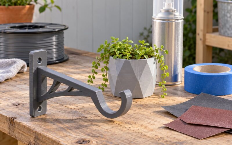
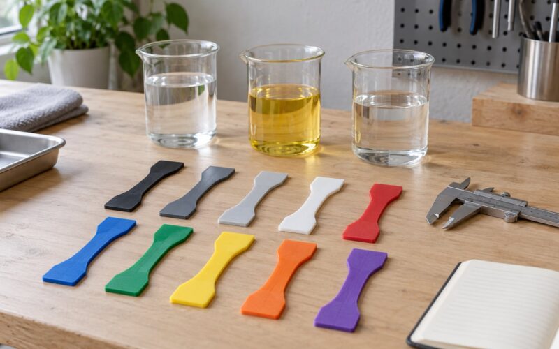
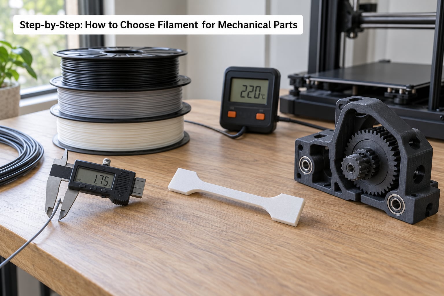
When two materials are close on paper, print a coupon of each rather than arguing. Print a small tensile bar in the same orientation as the real part, plus a thin wall strip that will flex, and a hook or cantilever that carries the load in one direction.
Test the parts against your real numbers: load the cantilever to your working load plus a margin, cycle the flex strip a few hundred times, and drop the tensile bar or heat-soak it if heat is part of the brief. Where two materials survive, choose the one that deformed slightly before breaking rather than the one that shattered.
Keep the coupons. They are the evidence that the material choice was deliberate, and they double as a reference when a batch behaves differently months later.
A cheap coupon set covers most of the decisions: a flat bar for tension, a stepped cantilever for bending, a strip at your working wall thickness for flex, and a small disc with a hole for fit. Print them in the orientation the real part will use, because a coupon printed flat proves nothing about a part printed on edge.
7. Validate the finished part under real conditions
Install the part, then check fit, motion and clearance before you trust it with a load. A bracket that fits loosely at one corner puts all the bending into one layer line, no matter how good the filament was.
Load it to your working condition, not to destruction, and watch what moves. Any visible flex that does not return means you are in creep territory, which is a material problem, not a design problem. A crack that starts at the layer line and runs straight across is a layer-adhesion problem, and the fix is orientation, temperature and slower cooling rather than a stronger plastic.
For long-running parts, write a simple soak test into the schedule: leave the part in a warm car, on a sunny sill or next to the machine for a week, then check the critical dimension and the load path again. Most surprises show up in that week, not on day one.
Finally, document what you did: material, brand and batch number, drying temperature and duration, storage box and desiccant, nozzle temperature, bed temperature, layer height, wall count, infill pattern and orientation. Six months from now the second identical part depends entirely on that record.
Common Mechanical-Filament Mistakes
Choosing by tensile strength. A number on a datasheet is measured on a moulded bar. Your part will be weaker, sometimes considerably weaker, and weakest of all between layers. Choose against the failure you expect, not for the headline figure.
Printing with the load across the layer lines. This is the single most common mechanical mistake. Rotate the part so the primary load runs through the solid walls in the XY plane. The Z direction typically gives up a large share of the material’s listed strength, and that gap decides whether a part survives.
Too few walls and light infill. The outer perimeters do most of the structural work. Four to six walls, around 40 to 60 percent infill with a gyroid or cubic pattern, gives far better results than 15 percent grid. Below about three walls, printed parts feel hollow and bend like they are. Gyroid and cubic patterns behave more like a uniform lattice and carry load in several directions at once, while a plain grid concentrates strength along two axes and gives up quickly when the load arrives from anywhere else.
Layer height matters as much as infill here. Thinner layers slow the print and shrink the Z gap, and on a part that depends on inter-layer bonding that is usually worth the extra hours. Fewer, taller layers print faster but leave a visible and mechanically weaker seam.
Skipping the drying step on nylon or PETG. Wet filament bonds badly and spits bubbles. Dry nylon at roughly 70 to 80 °C for 8 to 12 hours and PETG at 55 to 65 °C for 4 to 6 hours, then print from a sealed box with desiccant and refill only what you need.
Printing engineering material cold. Warping is usually a temperature problem. An enclosed chamber with a heated bed above 80 °C, a light brim or a release agent, and a slower first layer fix most of it. A heavy raft on a cold bed just adds a plate that peels off with the part.
Using a brass nozzle with abrasive filament. Glass and carbon filled filaments wear brass quickly, and the wear changes line width. Fit a hardened steel or ruby nozzle, and check it periodically once you start a batch of functional parts.
Opening nylon spools and leaving them open. Drying helps once; storage protects every day after. Use a dry box, keep a spare of desiccant in the lid, and buy the sizes you will actually finish in a season.
Trusting a filament with no traceable batch. When two spools from the same brand behave differently, batch consistency is the usual reason. Look for a declared diameter tolerance and roundness (quality 1.75 mm filament is typically specified within about ±0.03 mm), sealed moisture-controlled packaging, and a lot or batch number you can quote to the seller. That is a more reliable filter than any logo, and it answers the question engineering-filament buyers ask most often in community threads.
Ignoring the point where printing stops making sense. Injection moulding and CNC machining win once you need hundreds of identical parts with consistent tolerances. FDM printing makes economic sense for prototypes, jigs, one-offs, low volumes and parts that would be expensive to tool. Know which side of that line you are on before you design the part.
Confusing post-processing with a fix. Acetone vapour smoothing gives ABS and ASA a better surface and a slight dimensional change, and heat-setting or annealing can improve crystallinity in some polyamides, but neither repairs a bad layer bond or a badly oriented part. Post-process a good print, never a bad one.
Assuming every part needs a different material. Most assemblies work fine with two: a stiff material for the structural bodies and a tough or flexible one for the interface parts. Keeping the count low cuts drying time, nozzle changes and inventory, and every extra material on the machine is another variable to troubleshoot at 11pm. Staying with one material family also keeps spares, nozzles and drying times down.
Frequently Asked Questions
Is PLA or PETG better for mechanical parts?
PETG is the better all-round choice for mechanical parts. It takes more heat before it softens, bonds between layers better than PLA, and survives impact without shattering, which suits brackets, enclosures and fixtures. PLA is still stiffer and prints finer detail, so keep it for display parts, jigs and anything that stays cool. If the part sees sustained load, sunlight or warmth, choose PETG or go to ABS, ASA or nylon.
What is the best filament for mechanical parts?
There is no single best filament, because parts fail in different ways. PETG covers most everyday load-bearing work. ABS or ASA handle heat and UV, nylon handles fatigue and wear, TPU handles flex and seals, and polycarbonate or carbon-fibre-reinforced nylons take the highest static loads. Start from the failure you need to design out, then confirm your printer can reach the nozzle temperature and keep the material dry.
What filament should I use for automotive or under-hood parts?
Under the hood, heat and chemical exposure drive the choice. ASA or polycarbonate handle sustained temperatures above 100 °C, while nylon handles fuel, oil and vibration but needs to be dried and enclosed. Avoid PLA and standard PETG entirely, since both soften well below under-hood temperatures. Polyphthalamide composites extend the ceiling further for the hottest locations, at the cost of demanding nozzle temperatures.
Do I need a hardened nozzle for carbon fiber filament?
Yes, for anything functional. Chopped carbon fibre and glass fibre filaments are abrasive and will wear a brass nozzle within hours, widening the orifice and changing your line width and tolerances. A hardened steel or ruby nozzle lasts far longer and keeps dimensions consistent. Check the nozzle periodically once you are producing functional parts, and keep spares on hand for long print batches.
How long does nylon filament need to dry before printing?
Most filament dryers for nylon use around 70 to 80 °C for 8 to 12 hours. Drying removes moisture already absorbed, but it is not the same as storage: an opened spool will reabsorb water within days in a typical workshop. Print from a sealed dry box with desiccant and refill only the material you need for the job. Wet nylon shows up as popping, heavy stringing and parts that split along the layer lines.
Why do my 3D printed parts break along the layer lines?
Layer adhesion is usually the answer, and it has three common causes. First, cooling: running the part fan at full speed cools each bead before it bonds to the one below. Second, temperature: printing too cool weakens the weld between layers. Third, moisture, which is the usual culprit for nylon, polycarbonate and PETG. Print hotter, slow the cooling, dry the filament and orient the part so the load runs through the walls in the XY plane.
Conclusion
Choosing filament for mechanical parts is a short sequence: document the load, temperature, tolerances and printer limits first, pick the material family whose failure mode you can live with, then prove it with a coupon before you print the batch.
Start today by filling in the requirement sheet for your part. Loads, service temperature, tolerances, printer ceiling, nozzle type. Everything after that becomes a much shorter conversation.