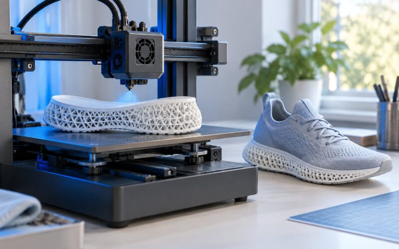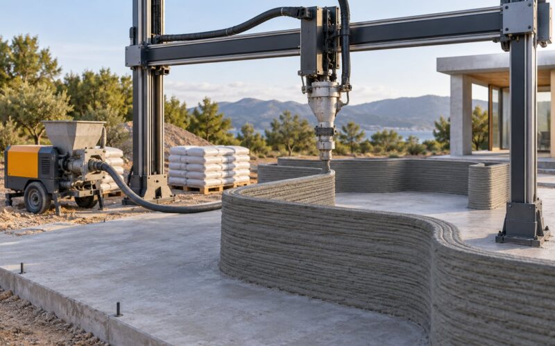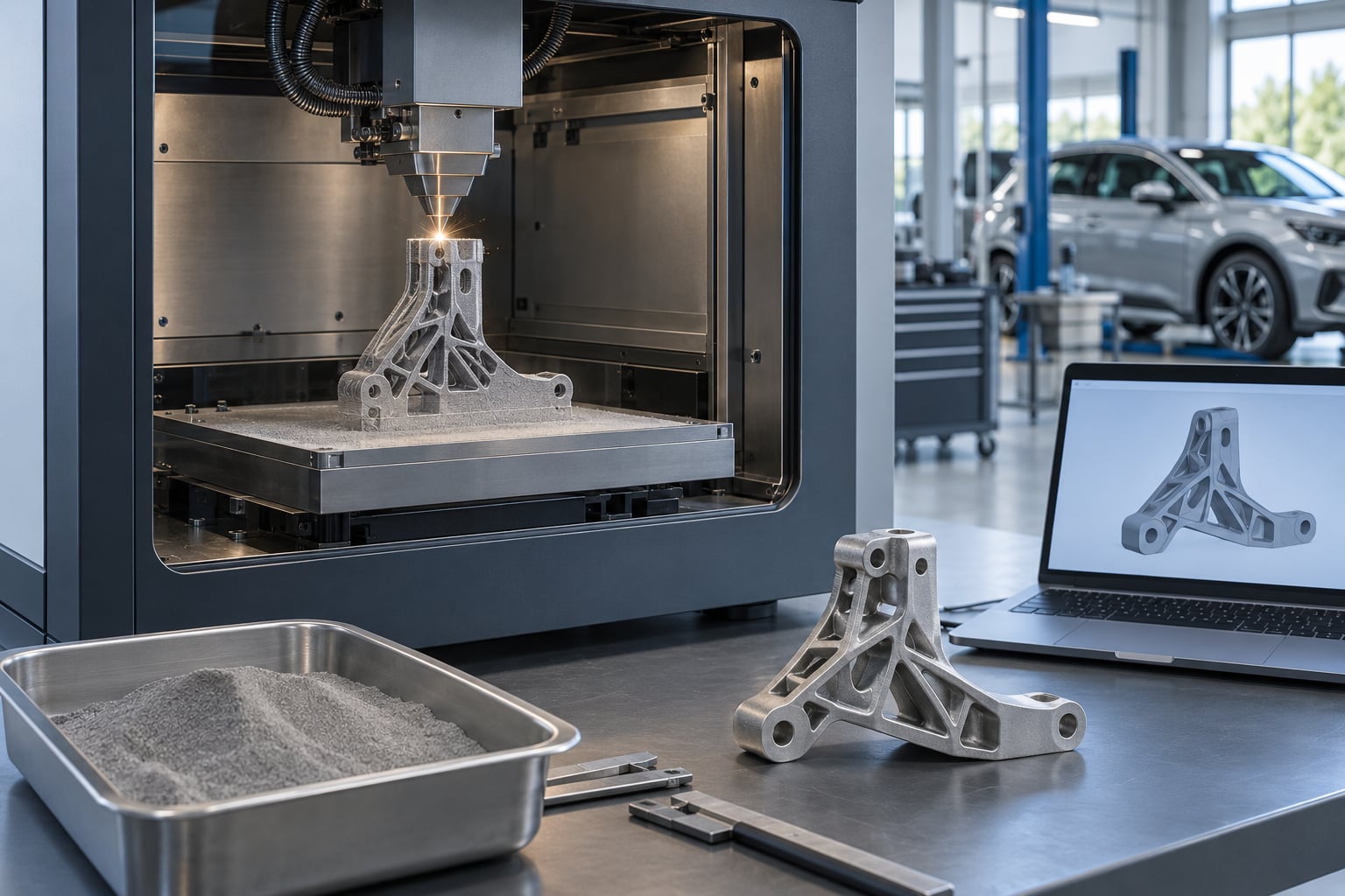
3D printing in automotive manufacturing means building vehicle parts layer by layer from a digital CAD model, so automakers can prototype, tool, produce and repair components without waiting on molds or casting dies. As of 2026 it is used across the whole vehicle development cycle, from the first styling model to end-of-line fixtures and on-demand spare parts. Where it wins is narrow but real: complex geometry, short lead times and low volumes, against stamping and injection molding for everything else.
The money gets saved where volumes are low and geometry is awkward, not where a million identical brackets are needed every year. That single pattern explains almost every sensible application in this article.
Table of Contents
- 1What Is 3D Printing in Automotive Manufacturing?
- 2How Is 3D Printing Used in Automotive Manufacturing?
- 3What Automotive Parts Can Be 3D Printed?
- 4Why 3D Printing in Automotive Manufacturing Is Different from Conventional Manufacturing
- 5Which Materials Are Used for Automotive 3D Printing?
- 6What Are the Main Benefits for Automotive Manufacturers?
- 7What Are the Limitations, Costs and Risks?
- 8How Can a Company Move from Prototyping to Production?
- 9Frequently Asked Questions
- 10Is 3D printing suitable for automotive production parts?
- 11Which automotive parts are best suited to 3D printing?
- 12What materials are commonly used in automotive additive manufacturing?
- 13How long does it take to 3D print an automotive part?
- 14How does automotive 3D printing compare with injection molding and CNC machining?
- 15Conclusion
What Is 3D Printing in Automotive Manufacturing?
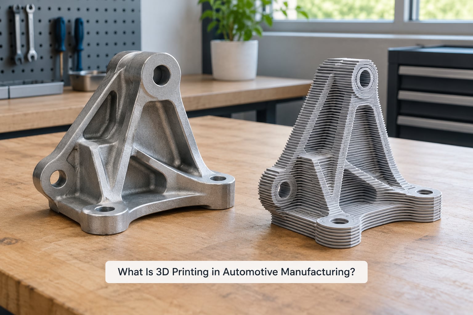
3D printing in automotive manufacturing is additive manufacturing: a printer builds a solid part by adding thin layers of polymer powder, resin, filament or metal powder to a digital model, rather than removing material from a block the way machining does. In a vehicle program it is used for five things above all else:
- Rapid prototyping — full-scale concept models, styling bucks and functional test parts for design reviews.
- Tooling and production aids — assembly jigs, weld fixtures, drill templates, gauges and prototype injection molds.
- End-use parts — ducts, brackets, covers, connectors and heat exchangers that ship on the vehicle.
- MRO and spare parts — on-demand replacement components for models whose tooling has expired.
- Custom and low-volume production — motorsport parts, premium trim, coachbuilt bodywork and aftermarket pieces.
One useful clarification: the term 3D printing is the trade name, additive manufacturing is the standard term under ISO/ASTM, and automotive engineers use them interchangeably in practice. What distinguishes the automotive use of it is not the printing itself but where it sits, which is upstream of the stamping line and downstream of the design studio, inside a quality system that has to sign off on every part.
How Is 3D Printing Used in Automotive Manufacturing?
The workflow runs in seven stages, and the two that catch newcomers out are file preparation and post-processing. Printing itself is rarely the slowest part of the job.
| Stage | What happens | Where it bites |
|---|---|---|
| CAD modelling | Geometry is designed with the process in mind: overhangs, supports, minimum wall thickness, orientation on the build plate. | Designers trained on subtractive methods make support-free geometry impossible. |
| File preparation | The model is oriented, sliced and given supports, infill, layer thickness and speed settings. | Poor orientation causes failures and weak layer adhesion. |
| Material selection | Polymer, composite or alloy is matched to the mechanical duty and thermal environment. | Standard polymers soften near engine bay temperatures. |
| Printing | The build runs unattended, from hours for a small jig to days for a full-size body panel. | Machine uptime inside a plant is rarely as advertised. |
| Post-processing | Removal, support stripping, de-burring, heat treatment, machining of mating faces, sealing, painting or plating. | Often the largest hidden time and labour cost in the whole job. |
| Inspection | Dimensional checks, material verification, mechanical testing, sometimes non-destructive testing on critical parts. | Layer orientation and internal porosity need documented qualification data. |
| Integration | The part enters the BOM, the digital part library and the build schedule, with a drawing revision and a supplier record. | Without a part library the same bracket gets reprinted badly, five times. |
Once that chain is documented rather than ad hoc, the same design file can be reprinted for a different model year, a different plant or a different material without anyone redrawing it. That reusability is the quiet advantage most plants underestimate.
What Automotive Parts Can Be 3D Printed?
Almost any part that is low-volume, geometrically awkward, or has a short life is a candidate. The categories that show up repeatedly in automotive programs are:
- Prototypes and styling models — full-scale exteriors and interior mock-ups for design sign-off, where a model changes ten times before approval.
- Assembly jigs and fixtures — welding fit-up fixtures, drill guides, checking templates and ergonomic hand tools. Brose has published same-day robotic welding fixtures built on large-format printers, and Dorman Products has described 3D-printed test fixtures for component checking.
- Prototype and low-run tooling — soft tooling and bridge inserts for short production runs, and master models for short-shot molding rather than production molds.
- Aerodynamic and ducting parts — intake plenums, HVAC ducts, spoilers and diffusers. Formlabs reported a printed intake manifold running 40-50C cooler than an aluminium equivalent, because internal channels and lattice infill manage heat and flow in ways a solid casting cannot.
- End-use polymer parts — seat clips, brackets, covers and connectors. One published supplier case ran 250,000 seat clips on two powder-bed machines in a matter of weeks.
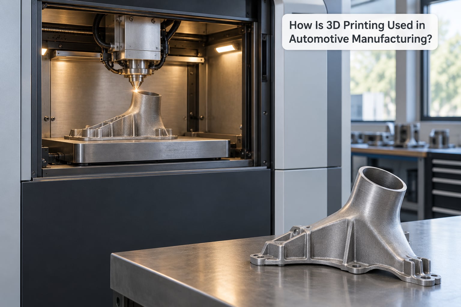
- Metal end-use parts — titanium brake calipers, exhaust components, heat exchangers and manifolds. Bugatti’s 3D-printed titanium caliper weighed 6.4 lb against 10.8 lb for the aluminium part it replaced.
- Spare parts and MRO — replacement parts for vehicles still in service when the original tool has expired or the supply chain has failed. Stratasys has documented this for a BMW X7, where printed stop-gap components covered a tooling delay.
- Motorsport and custom bodies — everything from control housings to full carbon composite bodywork on low-volume hypercars and track cars.
The pattern in that list is worth stating plainly: the parts that get printed are rarely the parts that are cheapest per kilogram. They are the parts where a single unit costs a day of engineering time to tool, or where the geometry would need an expensive multi-slide tool to make.
Why 3D Printing in Automotive Manufacturing Is Different from Conventional Manufacturing
The honest difference is that additive manufacturing has almost no fixed setup cost and a high per-part cost, while the conventional processes are the reverse. That single structural fact explains nearly every practical decision a plant makes.
| Criterion | 3D printing | Injection molding | CNC machining | Stamping / casting |
|---|---|---|---|---|
| Setup cost | Near zero beyond the machine | High: steel or aluminium tooling | Medium: fixtures and tooling setup | Very high: dies and molds |
| Economical volume | 1 to a few hundred parts | Thousands and up | Hundreds to low thousands | Tens of thousands and up |
| Lead time to first part | Hours to days | Weeks to months for the tool | Days | Months |
| Internal geometry | Lattices and cooling channels are free | Limited by tool insert complexity | Difficult, needs special cutters | Cores for castings, none for stampings |
| Material waste | Low for powder, high for filament support | Low once running; sprues and runners | High chip waste | Low to moderate |
| Surface finish as delivered | Rough, needs finishing | Moulded finish, no secondary work | Excellent as machined | Good, may need paint or trim |
| Part consistency, part to part | Varies with orientation and thermal history | Highly repeatable | Highly repeatable | Highly repeatable |
| Design change cost | Reprint the file | Modify and re-tool the mold | New fixtures and program | New die or pattern |
A decision framework that holds up in practice: choose additive when the volume is under a few hundred a year, the geometry has internal channels or undercuts, the part is obsolete or short-lived, or the lead time matters more than the part price. Choose injection molding or stamping when the part is a repeat item in the tens of thousands, the material is a commodity polymer, and the surface finish is customer-visible. Choose CNC when tolerances are tight, the raw material is expensive, and the fatigue data has to be unquestionable.
One more distinction engineers raise constantly, and it is fair: printed metal and machined metal are not interchangeable substitutes. Machining wins at volume and comes with decades of proven fatigue data. Printing wins on geometry and on low volume. Practitioners on engineering forums generally land on the same conclusion rather than picking a winner.
Which Materials Are Used for Automotive 3D Printing?
Material choice follows the process, and the process follows the duty. The table below covers the families that actually appear in vehicle programs.
| Material | Typical process | Strengths | Limits and post-processing | Common automotive use |
|---|---|---|---|---|
| ABS and ASA | FFF, SLS | Cheap, tough, paints and glues well | Warps, moderate heat resistance, needs priming and paint for a finished look | Styling models, interior trim, jigs |
| Polycarbonate | FFF | High impact and heat resistance, dimensionally stable | Needs careful drying; stringing and support marks | Functional prototypes, load-bearing covers, ducts |
| Nylon 12 and Nylon 12 GF | SLS, PA12 FFF | Strong, fatigue resistant, good chemical resistance, no support needed in SLS | Moisture uptake, rough as-built surface; SLS parts are often bead-blasted | End-use clips, connectors, retainers, fixtures |
| Photopolymer resins | SLA, DLP | Fine detail, smooth surfaces, fast turnaround | Brittle unless toughened; limited heat and UV resistance | Patterns, wind-tunnel models, gauges, trim prototypes |
| Carbon fiber reinforced polymer | FFF, SLS, SLA | Stiff and light with a far better stiffness-to-weight ratio than plastic | Abrasive to nozzles, anisotropic, needs resin infusion or a surface coat for finish | Bodywork, spoilers, control housings, race body panels |
| Aluminium alloys | SLM, DMLS, binder jetting | Light, strong, thermally conductive, well characterised | Needs heat treatment, support removal, HIP or stress relief and machining of mating faces | Heat exchangers, brackets, exhaust and intake parts |
| Titanium alloys | SLM, EBM | Very high strength-to-weight, corrosion resistant, biocompatible | Expensive, slow, demanding on machines; extensive post-processing | Brake calipers, connecting hardware, motorsport and aerospace-adjacent parts |
| Composites and resins | Resin infusion, RTM over printed shells | Moulded-surface finish with printed tooling underneath | Multi-stage process, needs careful control of fibre and resin | Coachbuilt panels, low-volume bodywork |
Two rules of thumb. If the part will sit in an engine bay or a sunlit dashboard, choose a glass-filled nylon or a thermoplastic engineered for temperature rather than a standard PLA prototype material. If a printed part is going to be painted or show, decide early who is doing the finishing, because that labour is usually larger than the print itself.
What Are the Main Benefits for Automotive Manufacturers?
Eight benefits come up repeatedly, though not with equal evidence behind them.
- Faster design iteration — a full-scale model that took a modeler three weeks to carve can be printed overnight, so design reviews happen on the real object rather than a rendering.
- Shorter lead time — no tool to wait for. Published cases quote fixture lead times cut by around 30 percent and same-day fixture availability.
- Lower upfront tooling cost — for a short run, a printed bridge or soft tool replaces a machined steel insert that would take months.
- Lightweighting — lattice and topology-optimised internals cut mass where stiffness is what matters. The titanium caliper example saved roughly 4.4 lb over aluminium.
- Part consolidation — several bolted components become one printed assembly with fewer fasteners, fewer joints and less leak path.
- Internal geometry that conventional methods cannot make — conformal cooling channels, undercuts and integrated sensor pockets.
- Supply chain resilience — a digital part library means a broken supplier, an expired tool or a halted assembly line does not have to stop production.
- Mass customization — coachbuilders and service vehicles can offer fitted interiors and bodywork without a bespoke mold per customer.
The first three are proven and easy to measure. The last three are real but application-dependent, and the eighth is still a niche rather than a mainstream production model. Treat any vendor claim of dramatic savings on a high-volume part as something to verify against your own volume and finish requirements.
What Are the Limitations, Costs and Risks?
This is the section most supplier pages skip, and it is where adoption actually stalls.
- Build rate and throughput — a powder bed fuses a few cubic centimetres an hour. A stamping line produces a body panel in seconds. Additive does not compete with a high-volume line and is not trying to.
- Anisotropy and layer adhesion — printed parts are strongest in the load direction and weakest between layers, which is exactly where fatigue cracks start. Engineers on forums are blunt about this: qualification data is scarce and layer orientation has to be specified on the drawing, not decided at the machine.
- Surface finish and appearance — visible layer lines make a part read as cheap. Sanding, priming, painting, bead blasting or plating adds hours and labour per part.
- Repeatability — porosity and thermal history vary between builds. Each machine, material batch and orientation combination needs its own qualification.
- Certification — safety-relevant parts are qualified against ISO/ASTM standards, and supplier quality accreditation is expected before a printed part can carry a load. This is the slowest part of adoption and nobody shortcuts it.
- Inspection and non-destructive testing — internal defects are hard to see. A mature program specifies CT or similar inspection for critical geometry rather than trusting the surface.
- Machine uptime in a plant environment — print failures, jams and powder handling interrupts are rarely covered in vendor material, and they do not care about your takt time.
- Digital IP and cybersecurity — a part library is an asset, and the CAD data behind it deserves the same access control as any other manufacturing data.
On cost, resist the single-number comparison. The drivers that decide whether additive is cheaper are machine depreciation, machine hours, material by weight, powder refresh rate, operator hours, post-processing hours, inspection hours and scrap rate. A printed part at a fraction of the machine cost can be more expensive once a technician spends six hours prepping the surface. Model the full cost per good part, not the print time.
How Can a Company Move from Prototyping to Production?
Adoption works better as a sequence of small commitments than as a single equipment purchase. A practical path looks like this:
- Pick candidate parts, honestly. Rank parts by volume, tool cost, lead time and geometry. Fixtures and short-run tooling usually win the first round because they carry no safety liability.
- Write material and design rules. Set minimum wall thickness, supported overhang angles, feature sizes and allowed orientation, and put them in the design standard. Retrofitting rules after 200 prints is expensive.
- Prototype and test. Print test coupons, not just the part. Test them for the loads and temperatures the real part sees, including vibration and fluids.
- Qualify the process, not the prototype. Document machine, material batch, orientation, parameters and post-processing route. A part that passes once is data, not a qualification.
- Plan post-processing and inspection up front. Decide who finishes, on what, and to what standard, and write it into the route card.
- Validate safety and compliance for anything structural, and involve quality early rather than after the first production dispute.
- Scale one part family at a time, and only move equipment to production status once a part has a repeat build history you trust.
Before committing to production-grade machines, ask a supplier: what is the documented uptime on this specific configuration, what is the scrap rate on your geometry, what qualification data exists for this material in this orientation, who does the post-processing, and what is the cost of a failed build including the powder. A vendor who answers all five clearly is worth more than one who quotes a build rate.
Frequently Asked Questions
Is 3D printing suitable for automotive production parts?
Yes, for specific parts and at specific volumes. Automotive 3D printing is well established for assembly jigs, weld fixtures, ducting, clips, brackets, heat exchangers, and end-of-line parts, and it works for structural components when the material and process are qualified to ISO/ASTM standards. It is not competitive with injection molding or stamping for a repeat part in the tens of thousands. The decision rule is simple: low volume plus complex geometry plus short lead time equals additive.
Which automotive parts are best suited to 3D printing?
The best candidates are parts that are low-volume, geometrically awkward, or short-lived. In practice that means prototypes and styling models, assembly jigs and check fixtures, prototype and short-run tooling, HVAC and intake ducting, end-use polymer clips and connectors, on-demand spare parts for vehicles still in service, and motorsport or coachbuilt bodywork. A useful filter: if making one part would require an expensive multi-slide tool, additive is probably the better route.
What materials are commonly used in automotive additive manufacturing?
Three families cover almost everything. Polymers and composites include ABS, polycarbonate, nylon 12 and glass-filled nylon, photopolymer resins, and carbon fiber reinforced filament or powder. Metals include aluminium and titanium alloys processed by selective laser melting, direct metal laser sintering or binder jetting. Glass-filled nylon and aluminium suit functional end-use parts, while carbon fiber composites suit bodywork and lightweight panels. Each material brings its own post-processing and finishing requirements.
How long does it take to 3D print an automotive part?
It depends far more on the part than the printer. A small fixture on a large-format polymer machine can be finished the same day, while a full-size body panel or a metal heat exchanger can take days, and post-processing may add as much time again. Suppliers report same-day welding fixtures and large production runs of hundreds of thousands of small parts over a few weeks. Always quote lead time including finishing, inspection and any machining, not print time alone.
How does automotive 3D printing compare with injection molding and CNC machining?
Additive manufacturing has almost no setup cost and a higher cost per part, which is the reverse of injection molding and stamping. CNC machining sits in between, with moderate setup and excellent tolerances and fatigue data. Printing wins on low volume, lead time, internal channels and undercuts; molding and stamping win on high volume and finish; machining wins on tight tolerances and proven material data. The break-even point usually arrives somewhere in the low hundreds of parts per year.
Conclusion
3D printing in automotive manufacturing earns its place where conventional tooling cannot justify itself: low-volume parts, complex geometry, fast-changing prototypes, on-demand spares and the fixtures that keep a line running. It is not a replacement for the stamping press, and any pitch that frames it that way should be treated carefully.
Start by choosing one low-volume or geometrically awkward part and running a controlled feasibility study on it. Print it, finish it properly, measure lead time, cost per good part and quality against the conventional alternative, and document every hour. That single study will tell a plant more about whether to scale than any market forecast will.