Yes, you can 3D print replacement knobs and clips at home, and most people get a part that fits on the second try. The workflow never changes: measure the original, model it with a deliberate clearance, print a small tolerance test, then print the real part and fit it. PETG is the sensible default filament for almost every replacement.
The reason people end up doing this is dull and practical. Manufacturers sell knobs, clips and feet as part of a whole assembly, or not at all, so one snapped plastic part can mean a new appliance front, a new set of blinds, or a scrapped PC case. A few grams of filament and an hour of your evening is a fair trade.
There are limits, and they matter. Do not print brakes, airbags, seatbelts, suspension parts, or anything you plan to hang above your head. Everything below applies to the small, non-safety-critical plastic parts that people twist, push or click every day.
Table of Contents
- 1What You Need
- 2Step-by-Step
- 31. Measure the Original Knob or Clip
- 42. Create or Adjust the Replacement Model
- 53. Choose a Durable Filament
- 64. Set Orientation, Supports, and Slicing Settings
- 75. Print and Test the Replacement
- 86. Finish and Install the Part
- 9Common Mistakes
- 10Frequently Asked Questions
- 11Can you 3D print replacement parts?
- 12Can you 3D print a knob?
- 13How much tolerance do 3D-printed parts need?
- 14How do I model a broken part if I cannot use CAD?
- 15Is it legal to 3D print a replacement part?
- 16Conclusion
What You Need
If you want to print replacement knobs and clips, the tool list is short, and only one item on it really decides whether the job goes well.
- An FDM printer. Any machine with a 0.4 mm nozzle will do. These parts are small and they do not ask anything unusual of a hot end.
- A slicer. PrusaSlicer, OrcaSlicer or Cura all handle a part this size fine.
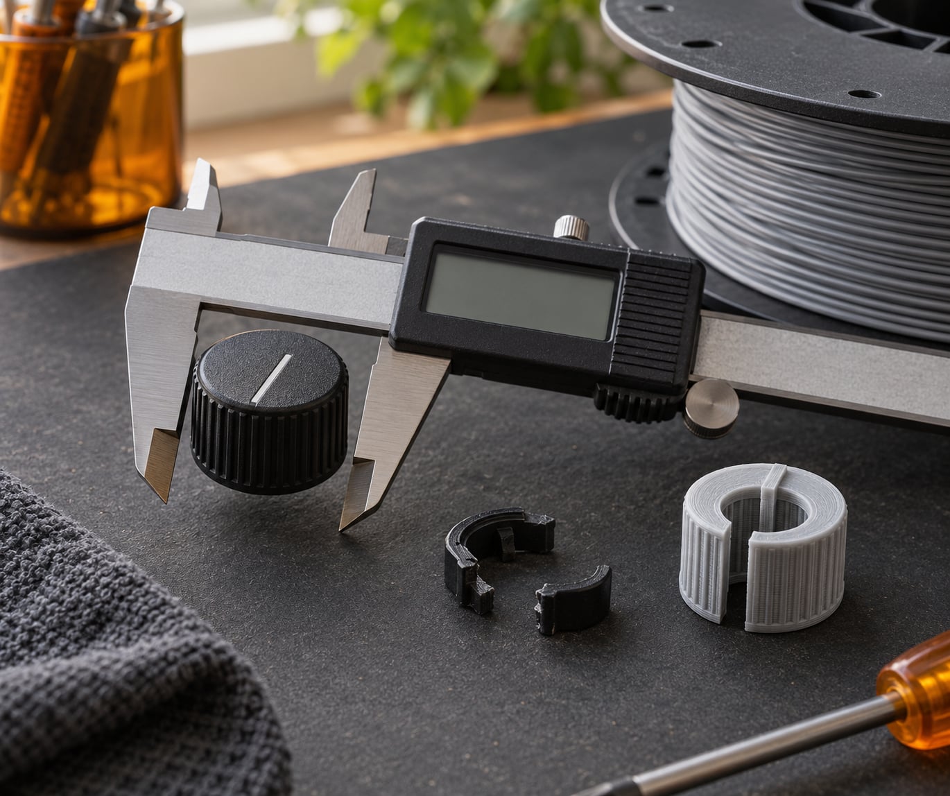
- Digital calipers. The single most important tool on this list, and the cheapest thing you will buy for it.
- The broken original. Keep every piece. A snapped clip in two halves is more useful than no clip at all, because you can measure each half.
- Filament. PETG or PLA+ to start, TPU for a clip that needs to flex, ABS or ASA if the part sits near heat.
- Modelling software. Fusion 360 is free for personal use and is the usual recommendation. Tinkercad and Onshape work too if you prefer something lighter.
- Optional extras. A metal dowel or round file for cleaning a bore, 180-grit sandpaper, a heat-set insert and an M3 screw, masking tape for measuring, and a phone for the photo fallback below.
Buy the calipers before anything else. Guessing the bore diameter from memory is how people end up reprinting a knob four times.
Step-by-Step
Six steps, in order. The first three are quick, the printing is the slow part, and the last step is where you avoid damaging the thing you were repairing.
1. Measure the Original Knob or Clip
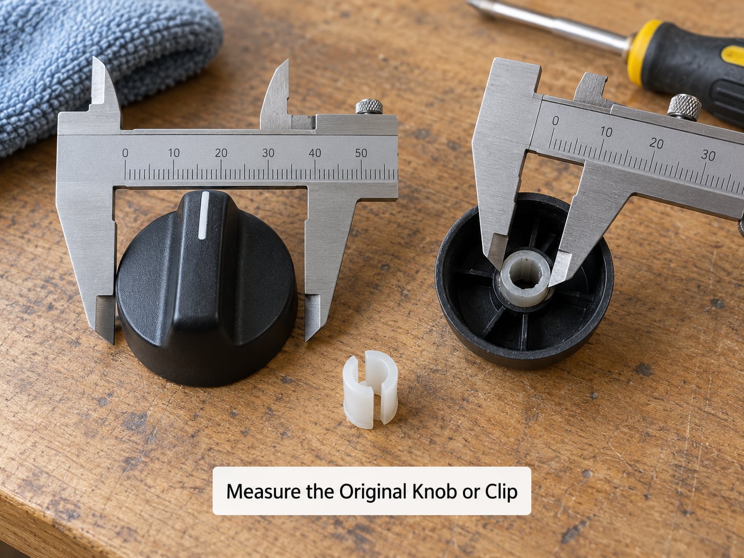
Measure the bore, the outside diameter, the length and every surface the part touches, then write the numbers down.
For a knob, record the shaft bore at three depths: at the face, in the middle and near the back. Cheap plastic knobs are rarely round, so a single reading can be wrong by a few tenths of a millimetre. If the shaft has a flat on it, measure across the flats and across the corners separately, and note which way round the flat faced.
For a clip, you need the overall length, the wall thickness, the length and angle of the flexible leg, the width of the slot it grabs, and the hole positions if it screws down. Calipers are wrong on the curved outer wall of most clips because the jaws measure across the outside, so photograph the profile instead.
That photo trick is the one people in the r/3Dprinting threads reach for when calipers will not help: lay the part flat on white paper, put a ruler in the same plane, take a straight-on phone photo, then correct the perspective in your editor so the ruler reads true. You get dimensions accurate to roughly a quarter millimetre, which is enough to model from and refine with a test print.
Two habits save trouble later. Keep the broken original in pieces rather than binning it, and take one photo of how the part sat before you took it off. Orientation matters, especially for a D-shaft knob or a clip that only flexes one way.
2. Create or Adjust the Replacement Model
Find an existing model and edit it before you build one from scratch, and make your mating surfaces 0.1 to 0.2 mm larger than the original.
Thangs, Printables and MakerWorld all have knobs and clips for common appliances and printers, and editing a model you downloaded takes minutes compared with an evening of CAD. Check the licence before printing anything commercial, and measure the downloaded model against your own measurements before trusting it.
If you are modelling yourself, work from the outside in. Copy the outer shape of the original first, then cut the bore, then add the retention feature. For a round shaft, make the bore 0.1 to 0.2 mm bigger than the shaft. For a D-shaft, add 0.2 mm to the flat-to-flat dimension, because that is the surface that carries the load and the one that will bind if it is tight.
For clips, copy the flexible leg from the original rather than inventing a new one. Snap fits fail because the leg is too short or too thick, and the part you already have is proof of a working geometry.
| Fit type | Gap per side | Where it works |
|---|---|---|
| Press fit | 0 mm to 0.05 mm interference | A knob hole that grips a shaft with no fastener |
| Snug slide | 0.1 to 0.2 mm | Round bores, clip legs, holes that take a screw |
| Loose fit | 0.3 to 0.4 mm | First prints, bores you can still ream out |
If you have no CAD experience at all, photogrammetry apps that build a 3D model from a ring of phone photos will capture a small clip’s shape for you. The mesh comes out slightly noisy, but you can scale it, smooth it and set your own clearance afterwards, which is usually faster than measuring by hand.
3. Choose a Durable Filament
Pick PETG for most replacement knobs and clips, because it tolerates heat, impact and repeated flexing better than PLA without needing an enclosure.
| Material | Stiffens or softens around | Good for |
|---|---|---|
| PLA+ | 55 to 60 °C | Knobs on cool equipment, prototypes, fit tests |
| PETG | 80 °C | Most knobs and rigid clips, handles, feet, brackets |
| ABS / ASA | 100 °C | Parts near a hot end, a heater or a warm appliance panel |
| TPU | Flexible, shore 95A | A clip that has to snap on and off by hand |
| Nylon / PA-CF | High heat, tough | Sliding wear parts, tight-tolerance bores |
PLA is tempting because it prints cleanly and shows detail, and it is the right call for a fit test. It softens in a warm car or on a sunny windowsill, so I would not put a PLA knob on something that gets warm. PETG prints a little stringier, especially in a small bore, which is worth knowing before you blame the model.
TPU is the exception to the rigid default. A flexible clip printed in TPU with 20 to 30 percent infill will survive being pushed on and off far longer than a rigid one, as long as you print it slowly at around 20 to 30 mm/s so the nozzle does not drag it around.
4. Set Orientation, Supports, and Slicing Settings
There is no single universal setting, but for small parts a 0.16 to 0.2 mm layer height, 3 to 4 perimeters and 20 to 50 percent infill will hold up to daily handling.
Orientation decides more than the surface finish. Print a knob with the bore vertical, so the shaft hole has no elephant’s foot lip at the bottom edge, and so the load runs along the layers instead of peeling them apart. Print a clip with the flexible leg lying flat on the bed and its length running parallel to the layers, so flexing bends the part across many layers rather than pulling a single one apart.
If a part has to stand on its clip leg, angle it slightly so the legs are never perfectly vertical, and let the slicer add a small bridge over the top. Avoid any overhang sharper than about 45 degrees on a clip arm unless you are prepared to support it.
Supports are usually off for these parts. Turn them on only for a bore that has to face sideways, and use organic or tree supports rather than rigid ones, because tearing support off a finished clip is how small flexors snap.
Turn off or lower the outer perimeter speed on a small bore. Most slicers will otherwise race around a 6 mm hole and leave you a fuzzy ring that will not slide onto the shaft. A brim helps a small clip stick to the bed, and a brim is worth the scrap paper if the part is 30 mm across.
5. Print and Test the Replacement
Print a tolerance test before the real part, and check the fit on the original hardware rather than on your model.
A test coupon is a 10 mm ring printed at the same layer height and in the same orientation as the knob bore. It takes five minutes and tells you whether your gap is right before you spend an hour on the full part. Print two or three with different gaps if you are unsure, and push them onto the shaft one at a time.
Watch the first layer of the real print. If the outline is not sticking, stop the print and fix adhesion, because a lifted first layer changes every dimension above it. Do not push through a bad first three layers hoping the slicer settings were wrong.
When the print finishes, measure the bore with the calipers before you install anything. Compare it with your target. A knob bore that is 0.1 mm under spec will still mount, but it may crack the shaft or the knob wall when you push it home.
For a clip, cycle it twenty times by hand. If it needs a tool or it is already loosening after five pushes, the undercut is too deep or the leg is too short, and you want to find that now rather than in six months.
6. Finish and Install the Part
Clean up the part and fit it without force, because a replacement that needs a mallet will damage the housing you were trying to repair.
Remove supports while the part is still slightly warm, working from the thickest area toward the fine features so you do not lever on the clip arm. Break the support off rather than twisting it.
To open up a bore, wrap 180-grit sandpaper around a round dowel of the right diameter and rotate the knob around it. Take 0.1 mm off at a time and re-test. If you want to go faster, a hand reamer in the right size is far better than a drill, and you can buy one for the shaft size you measured.
Skip acetone vapour smoothing on any part that has to fit. The vapour slightly shrinks the surface it touches and closes a bore by a few hundredths of a millimetre, which is exactly the tolerance you spent an hour setting up.
Paint and fill are fine, but prime and paint after the fit test, not before. Mask the bore, and if you printed a knurl or grip texture, a thin filler coat followed by a matte paint will make it feel far better under a thumb than bare layer lines do.
Finally, decide how the knob grips before you install it. A press fit needs a light push with two fingers. If it binds, take it out and ream it rather than forcing it. A set screw gives a controlled, repairable grip and costs one tapped hole, and a heat-set insert gives you a proper thread for repeated removal, which is the better choice on a knob you will twist every day.
Common Mistakes
Almost every failed replacement comes down to one of four things: a dimension measured once, a gap guessed, a part printed flat, or a fit tested on the screen instead of on the hardware.
| Symptom | Cause | Fix |
|---|---|---|
| Knob will not go on | Bore printed small, or shrinkage not compensated | Ream or sand the bore; on the next print add 0.1 mm to the gap |
| Knob spins on the shaft | No flat, no set screw, bore too loose | Add a D-flat, a set screw, or a heat-set insert instead of a tighter bore |
| Knob splits at the shaft | Load across the layers, or infill too low | Reprint bore-up, 4 perimeters, 40 percent infill or more |
| Clip is too tight | Undercut too deep for the filament | Reduce the undercut, or switch to TPU |
| Clip cracks at a layer line | Flexor printed across the layers | Rotate the part so the leg runs parallel to the bed |
| Part will not sit flat | Elephant’s foot on the first layers | Set an elephant’s foot compensation, or add a chamfer |
| Bore is fuzzy and oversized | Stringing and blobbing at low speed | Slow the perimeter, enable combing, raise the temperature a few degrees |
A few quick habits catch most of these. Print one small coupon before the real part, every time. Measure at three points rather than one. Never plan a fit you have not tested against the actual broken part. And when a print is close but wrong, change one number in the slicer or the model rather than three, so you know what fixed it.
Frequently Asked Questions
Can you 3D print replacement parts?
Yes, for most small plastic parts. Knobs, clips, feet, covers and trim pieces are ideal: they are small, they take a load across the layers rather than a shock, and nobody is relying on them to fail safely. Measure the original, model a version with a 0.1 to 0.2 mm gap, print a tolerance coupon first, then the real part in PETG. Avoid anything involved with brakes, steering, airbags, seatbelts or overhead loads.
Can you 3D print a knob?
Yes, and it is one of the easier first functional prints. Print the bore vertically so there is no elephant’s foot lip in the hole, use 3 to 4 perimeters with 20 to 50 percent infill, and give the bore 0.1 to 0.2 mm more than the shaft. Round shafts grip by interference, D-shafts need a matching flat, and a knob you remove often is better off with a set screw or a heat-set insert than with a tight press fit.
How much tolerance do 3D-printed parts need?
A press fit needs the two surfaces to touch or overlap slightly, so zero to 0.05 mm of interference. A snug slide needs 0.1 to 0.2 mm per side, which is the most useful default for bores and clip legs. A loose fit of 0.3 to 0.4 mm suits a first print or a hole you can still ream. Printed parts vary by roughly 0.1 mm without calibration, so build these gaps in rather than modelling an exact nominal diameter.
How do I model a broken part if I cannot use CAD?
You have three routes. Download an existing model of the same part from Thangs, Printables or MakerWorld and edit the clearance, which is fastest. Use a photogrammetry app that builds a mesh from a ring of phone photos, then scale and smooth it. Or measure with calipers plus a phone photo taken next to a ruler, correct the perspective, and model from the corrected image. Most people combine the last two: scan for shape, calipers for the bore.
Is it legal to 3D print a replacement part?
Printing a part for your own broken appliance or vehicle is generally fine, and those parts are usually not sold on their own anyway. The lines to watch are reproducing a trademarked logo or badge, and printing something a patent covers for commercial sale. Keep prints for your own repair, leave the original markings off the replacement, and check your vehicle manufacturer and local rules before printing anything structural on a car.
Conclusion
Start by measuring, not by modelling. Calipers on the bore, a photo with a ruler for the profile, and the broken original kept in pieces. Then model the replacement with a slightly generous gap, print a small tolerance coupon to confirm it, and only then commit to the full part in PETG.
That sequence takes an hour end to end and it is the difference between a repair that lasts and a drawer full of failed knobs.