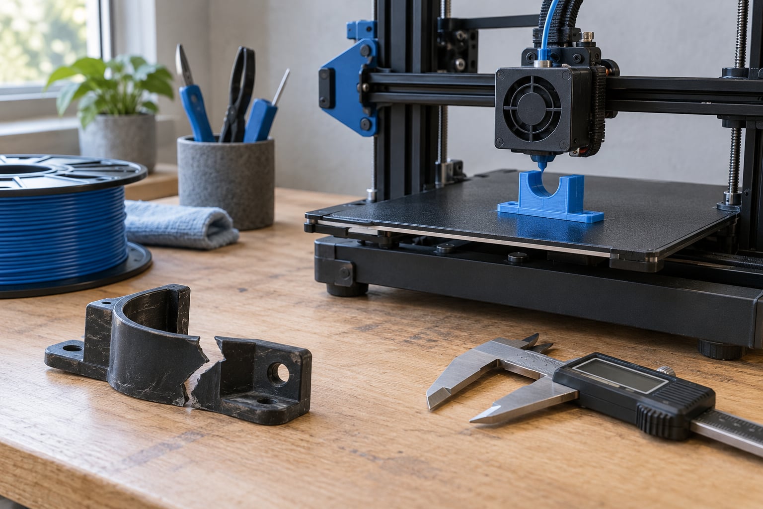
To fix a broken plastic part with 3D printing, you measure or scan the intact half of the part, model the missing section in CAD, print it in a filament matched to the original plastic, then bond or fit it into place. A small noncritical repair takes roughly two to four hours including print time; scanning and CAD work can stretch that to a weekend.
The reason people go this route instead of reaching for glue is simple. A snapped tab on a kettle lever, a broken appliance knob, a missing lid clip on a bucket, a cracked laptop bezel clip — manufacturers discontinued spare parts for most of these decades ago. Gluing restores a crack but not a missing load-bearing feature, and a printed replacement puts fresh material exactly where the stress was.
There is a catch worth saying up front. If a replacement part exists and arrives in a couple of days for a few dollars, buy it and save yourself the weekend. Printing wins when the part is discontinued, when the manufacturer never sold it separately, or when the original is on an appliance that is otherwise perfectly fine.
Below is the whole process, in order, with a check you can run at the end of each step so you know whether to move on or go back.
Table of Contents
- 1What You Need
- 2Step-by-Step
- 31. Inspect the Break and Decide Whether It Can Be Repaired
- 42. Scan or Measure the Broken Part
- 53. Model the Replacement or Reinforcement
- 64. Test the Fit Before Printing
- 75. Print the Part with the Right Settings
- 86. Prepare the Printed and Plastic Surfaces
- 97. Bond, Clamp, and Check the Repair
- 10Common Mistakes
- 11Frequently Asked Questions
- 12Can you repair any broken plastic part with a 3D printer?
- 13What plastic should I use to 3D print a replacement part?
- 14What adhesive works best between plastic and 3D-printed parts?
- 15Are 3D-printed plastic repairs strong enough for load-bearing applications?
- 16Do I need a 3D scanner to fix a broken part?
- 17How do I stop a 3D-printed repair from cracking again?
- 18Conclusion
What You Need
You need a way to capture the part’s shape, a way to model the missing half, a printer, and an adhesive that will hold plastic to plastic. Most of the tools are cheap or free; the two that take real time are the measurement and the CAD work.
To capture geometry you have four realistic options. Digital calipers give you accurate numbers on anything you can reach a jaw into. Reference photographs from several angles, shot close with good light and a scale reference in frame, let you match curves later. Phone photogrammetry apps turn a ring of photos into a mesh and are good for large surface features but weaker on small bores and thin clips. An entry-level 3D scanner gives you the cleanest result and is the fastest route once the part is larger than about 40 mm in every direction.
On the modelling side, parametric CAD such as FreeCAD, Fusion 360 or Tinkercad is the right tool because dimensions stay linked and you can change a clearance value without redrawing anything. Mesh editors work too when you are scanning, but a mesh is awkward to dimension reliably.
You also need: a slicer, 100 to 400 grit sandpaper or a file, isopropyl alcohol for degreasing, clamps or a printed jig to hold pressure while adhesive cures, and an adhesive matched to both plastics. More on adhesive choice in step 7.
Before anything gets near a powered device, unplug it. If the broken part carries mains voltage, holds a structural load on a vehicle, sits on a pressure boundary, or handles food or drink, treat it as out of scope and replace it. Printing is fine for housings, trim, latches, knobs and covers. It is not fine for anything that fails and injures someone.
Step-by-Step
1. Inspect the Break and Decide Whether It Can Be Repaired
Identify the plastic first, because it determines both the filament and the glue. Most consumer housings are ABS or ASA, appliance knobs are often POM or nylon, and toys, enclosures and printed spares are usually PLA or PETG. A stamped character on the plastic, a faint resin code in the moulding, or the sound and flex when you snap a hidden edge will usually tell you more than the colour.
Look at what is left around the break. Count the remaining walls and check whether the mounting bosses, screw holes and alignment features survived. If a screw boss is shattered rather than cleanly snapped, the fix is a printed boss with an embedded nut, not a glue job.
Then estimate the load. A trim clip that carries nothing but a lid weight is an easy print. A lever, hinge or latch that carries a person’s weight or a levering force needs a printed part with more walls, a generous fillet at the crack origin and metal reinforcement or a heat-set insert where wear happens.
Success check: you know the polymer, you know which features must stay intact, and you have decided between a printed replacement, a printed reinforcement bonded over the crack, or professional replacement. If the original geometry is gone in a way that leaves you guessing, stop here and buy the part.
2. Scan or Measure the Broken Part
Photograph the intact half from the front, back, both sides and at a slight angle, with a ruler in frame. Those photographs are your reference when the real part is no longer in your hand. On community repair threads the recurring question is exactly this: how do you get an accurate dimension set when half the reference geometry is gone.
The answer is that you only need the features the replacement has to match. Measure hole centres and diameters, wall thicknesses, overall length and width, and any dimension that controls how the part indexes into its neighbour. Read it off with calipers, and photograph the caliper jaws closed on the feature with the reading visible. That gives you both a number and a picture to argue from later.
Keep mating surfaces untouched. Clean the crack with alcohol before you scan so the model is not distorted by dust or by the burr around the fracture, and scan or photograph from a flat surface with the part held down.
Success check: you have a photo set plus a list of key dimensions, and the list covers every feature the replacement must mate with.
3. Model the Replacement or Reinforcement
Decide between a full replacement and a local reinforcement. A replacement is cleaner and stronger if the part is small. A reinforcement is better when the surviving part is a moulded item with a textured or curved surface you do not want to reprint, and when the crack sits in one place — a printed collar bonded over the fracture area works well there.
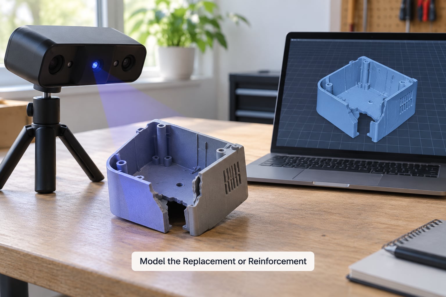
Whichever you pick, the design rules are the same:
- Wall thickness. At least three perimeters. For anything that carries real load, four to six. Thin single-perimeter walls snap along the layer line.
- Fillet radius. Add a generous radius where the load enters the part. A sharp internal corner is a stress riser and that is exactly where the original failed; a 3 to 5 mm fillet moves the failure point out of the model.
- Bosses and tabs. Rebuild screw bosses with extra material around the base. Give latches a small chamfer so the original part indexes into them.
- Clearance. Leave 0.2 to 0.3 mm extra on sliding fits and 0.1 to 0.2 mm on press fits. FDM printers vary more than people expect, and holes come out undersized.
- Orientation. Lay the part so the layer lines run across the load rather than along it, and put the flat bonding face down on the bed so it prints without support scarring.
- Draft. Add a small draft angle to anything that sits on the original plastic, or you will fight it during assembly.
If half the part is missing, mirror the intact half in CAD, thicken it, and rebuild only the features you need. Nobody publishes that trick clearly because it looks like cheating, but it works for symmetrical housings and covers.
Success check: you have an STL or 3MF, every clearance is at least 0.1 mm looser than the original measurement, and no sharp corner sits on the load path.
4. Test the Fit Before Printing
Print a scaled-down version at 40 to 50 percent, or a 5 mm tall test section of the critical feature. Ten minutes of printing saves an hour of fit-trimming, and this is the cheapest fix in the whole process.
Alternatively, check the slicer preview for wall placement: look at the cross-section and confirm the holes are not sitting half on a perimeter wall. If they are, rotate the model or nudge the seam rather than fighting the hole later with a file.
Also confirm the part will still assemble. If a cover now sits a fraction proud, the latch downstream will not close. This is where clearance decisions from step 3 get paid back.
Success check: the scaled test piece drops into the mating feature without force and closes.
5. Print the Part with the Right Settings
Match the filament to the job, not to what you have loaded. PLA is fine for trim and covers and softens in a warm car. PETG is the sensible default for anything that takes impact or moderate warmth. ABS or ASA matches most moulded housings and handles heat better, though both need an enclosure. Nylon is tough and heat resistant but absorbs moisture and warps without a heated chamber. TPU is flexible and bonds poorly to rigid plastic, so use it only where the original part was itself flexible. Resin gives fine detail and crisp fit but is brittle in thin sections.
- PLA — trim, covers, noncritical latches. Softens near a hot appliance.
- PETG — levers, clips, general indoor use. Watch for a stringy layer finish.
- ABS or ASA — moulded housings, parts near heat. Warps without an enclosure; ASA holds up to UV.
- Nylon — high-wear, heat, gear-like parts. Takes on moisture, needs drying first.
- TPU — gaskets and flexible tabs. Hard to bond to rigid plastic.
For strength, raise perimeters to four or more, set infill to 40 to 60 percent gyroid or cubic for internal parts, and keep the layer height modest at 0.15 to 0.2 mm. More perimeters help far more than more infill, because the perimeter walls carry most of the load and infill only stops the walls from bowing. Support contact surfaces with tree supports if your slicer has them, so the parting line is easy to sand flat.
One more thing that decides whether a repair survives: the direction of the load. Layer adhesion is the weak axis in FDM. If the crack force pulls along the layers, the part splits at the layer boundary. Rotate it in the slicer until the layers cross the load.
For anything structural, safety-related or carrying a person, get the geometry validated before you rely on it. A printed part can be engineered properly, but a household estimate is not engineering.
Success check: the print finished clean, the perimeter count is visible at the crack origin, and no layer line runs along the load direction.
6. Prepare the Printed and Plastic Surfaces
Remove supports while the part is still slightly warm and take light passes with flush cutters rather than twisting, which snaps thin walls. Knock the parting line flat with 100 grit, then 180 to 220 for the bonding face.
Now the step that most repairs fail at. Printed plastic is already smooth, and smooth surfaces give glue almost nothing to grab. Abrade the bonding face and the original plastic with 180 to 400 grit until both are matte, then clean both with isopropyl alcohol and let them dry fully. Dust and skin oil are the usual reason a “perfect” repair peels off a week later.
Do not sand the fit surfaces or the mating features. You spent print time on those clearances; give them away and you will be back at the slicer.
Success check: both bonding faces are uniformly matte, clean and dry, and the fit still slides without force.
7. Bond, Clamp, and Check the Repair
Pick an adhesive that works on both surfaces. For ABS or ASA to ABS, a solvent-weld approach — acetone on the joint, lightly, with ventilation — gives a genuine weld rather than a glue joint. For PETG and most printed parts, two-part epoxy is the reliable choice; cyanoacrylate works on rigid plastic but is brittle and will not fill a gap. For any gap you cannot close completely, use a gap-filling epoxy or a filler-loaded CA that holds a bridge.
Apply a thin, even bead. More adhesive is not more strength; excess glue squeezes out, telegraphs on the visible face and can starve the joint of the hardener it needs. Bring the parts together, align them, and clamp with light even pressure. Too much clamp force distorts thin walls and the part will not seat.
Let it cure for the full time the adhesive specifies, undisturbed, before you touch it. Then work through the function: check alignment, run a fastener in and out, cycle the mechanism several times, and apply the load gradually rather than all at once.
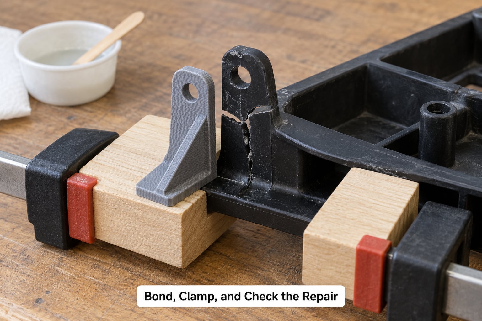
Success check: the joint holds under a slow, steady load and returns to position after cycling, with no creep and no crack forming at the fillet.
Common Mistakes
Guessing dimensions. The classic failure. If the part comes out slightly too tight or too loose, it is usually because a dimension was eyeballed rather than measured. Measure it, and print a scaled test first.
Using an adhesive that only sticks to one side. Super glue on a printed face is a coin flip. Clean, abrade and use epoxy or a solvent weld matched to the plastics.
Printing with the layer lines along the load. This is why printed repairs crack straight along a seam even when the walls are thick. Rotate the model 90 degrees in the slicer and print again.
A glossy bonding face. Printed plastic bonds poorly until it is scuffed. One pass with 180 grit usually fixes an entire repair.
Too much adhesive. A thick bead cures unevenly and squeezes out from the gap you were trying to fill. Thin and even is the rule.
Skipping the gradual load test. Snap the full force on first use and you will find out the repair is bad in the worst possible place. Ramp the load up over a few minutes instead.
Two shortcuts exist when a printer is not worth the effort. A 3D print pen deposits molten thermoplastic straight onto the crack and can weld small parts in place with no CAD at all, though it works on thin walls and fiddly geometry more than on big flat faces. Layered cyanoacrylate with a filler powder is the other. Worth knowing the honest limitations: makers who used the baking soda version described repairs that were strong at first and then turned brittle and degraded into brown goo over months, with talcum powder holding up better because it did not react as fast and allowed more cure time. Fine sand worked for tiny RC parts where weight mattered. Either technique is a fine stopgap; neither replaces a printed part when the feature carries load.
Frequently Asked Questions
Can you repair any broken plastic part with a 3D printer?
No. Printing works for plastic housing features, trim, clips, latches, knobs and covers where the surviving geometry gives you something to measure and match. It does not work for parts carrying mains voltage, pressure, food contact or structural loads on a vehicle or machine. It also struggles when the break destroyed the mounting boss and left no flat reference surface to model from.
What plastic should I use to 3D print a replacement part?
Match the original as closely as you can. PETG is the best general default because it takes impact and mild heat. Use ABS or ASA for moulded housings and anything near a hot appliance, nylon for high-wear or high-heat parts, and PLA only for light trim that stays cool. TPU suits flexible parts, and resin suits fine detail where the section is thick enough to stay out of brittle territory.
What adhesive works best between plastic and 3D-printed parts?
Two-part epoxy is the most dependable for PETG and most printed polymers once both surfaces are abraded and clean. For ABS or ASA to ABS, a solvent weld on the joint gives a stronger result than any glue. Cyanoacrylate is fast and bonds rigid plastic well but stays brittle and will not bridge a gap. Always test on a scrap offcut before committing to the part.
Are 3D-printed plastic repairs strong enough for load-bearing applications?
They can be, but only with deliberate design and orientation. Four or more perimeter walls, 40 to 60 percent infill, a generous fillet at the stress riser and layer lines running across the load rather than along it are the basics. Anything that holds a person, carries mains power or guards a moving machine needs engineering validation rather than a household estimate of wall thickness.
Do I need a 3D scanner to fix a broken part?
No. Calipers plus reference photographs cover a lot of small plastic parts, especially ones with flat faces and few features. Scanners and photogrammetry pay off when the part is curved, when you are reproducing a shape by eye, or when you want to reprint the whole item rather than just the missing piece. For parts under roughly 40 mm, careful measurement usually beats scanning.
How do I stop a 3D-printed repair from cracking again?
Most repeat cracks start at the same place the original failed, because the sharp corner is still there. Add a fillet radius of 3 to 5 mm so the load spreads across a wider area, rotate the part so layer lines cross the load direction, and increase perimeter count before adding infill. If the surface still shows a crack line, that corner needs more material, not a stronger filament.
Conclusion
Start by identifying the plastic and checking what load the failed feature was carrying, because both decide whether printing is even the right move. If the geometry survives well enough to measure, capture it properly with calipers and reference photographs before opening any CAD software. Design with more walls than you think you need, fillet the corner where the original broke, orient the layers across the load, then abrade both surfaces before you bond.