CT scanning for additive manufacturing quality control means using X-ray computed tomography to look inside a 3D-printed part without cutting it open. The scanner produces a 3D voxel volume that you can measure for internal porosity, inclusions, cracks and trapped powder, then overlay on the CAD model to check geometry. It is the only practical method that quantifies internal defects non-destructively and repeats the same measurement on every part.
That matters because metal additive manufacturing parts fail from the inside out. A surface that looks clean under a lamp can sit on top of a lack-of-fusion defect that a fatigue test will eventually find for you, in the airframe or in a patient’s hip. This guide covers what CT sees, where it fits in a quality plan, how to size a scan so it can actually resolve the defects you care about, and where a cheaper method does the job better.
Updated for 2026.
Table of Contents
- 1What Is CT Scanning for Additive Manufacturing Quality Control?
- 2How CT scanning for additive manufacturing quality control differs from other methods
- 3Why CT Inspection Matters for 3D-Printed Parts
- 4CT Scanning for Additive Manufacturing Quality Control at a Glance
- 5How Does CT Inspect an Additive Manufactured Part?
- 6What Types of CT Scanning Are Used for 3D Printing?
- 7How Do You Choose the Right CT Resolution?
- 8How Are CT Results Evaluated Against Print Quality Requirements?
- 9What Are the Limitations of CT for Additive Manufacturing Inspection?
- 10How Can Manufacturers Make CT Inspection More Cost-Effective?
- 11Frequently Asked Questions
- 12What is CT scanning used for in 3D printing quality control?
- 13What defects can CT scanning detect in additive manufacturing?
- 14Is CT scanning non-destructive?
- 15How long does a CT scan of a 3D printed part take?
- 16What resolution CT scan is needed for porosity detection?
- 17What is the difference between CT scanning and metallography?
- 18Should I buy a CT scanner or outsource CT inspection?
- 19What standards apply to CT inspection in additive manufacturing?
- 20Conclusion
What Is CT Scanning for Additive Manufacturing Quality Control?
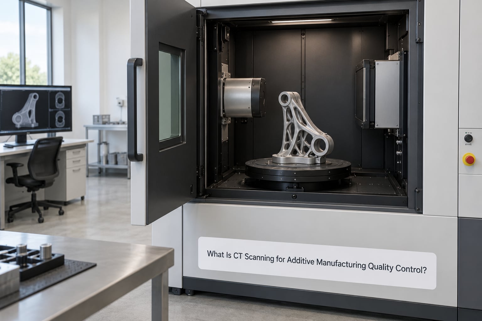
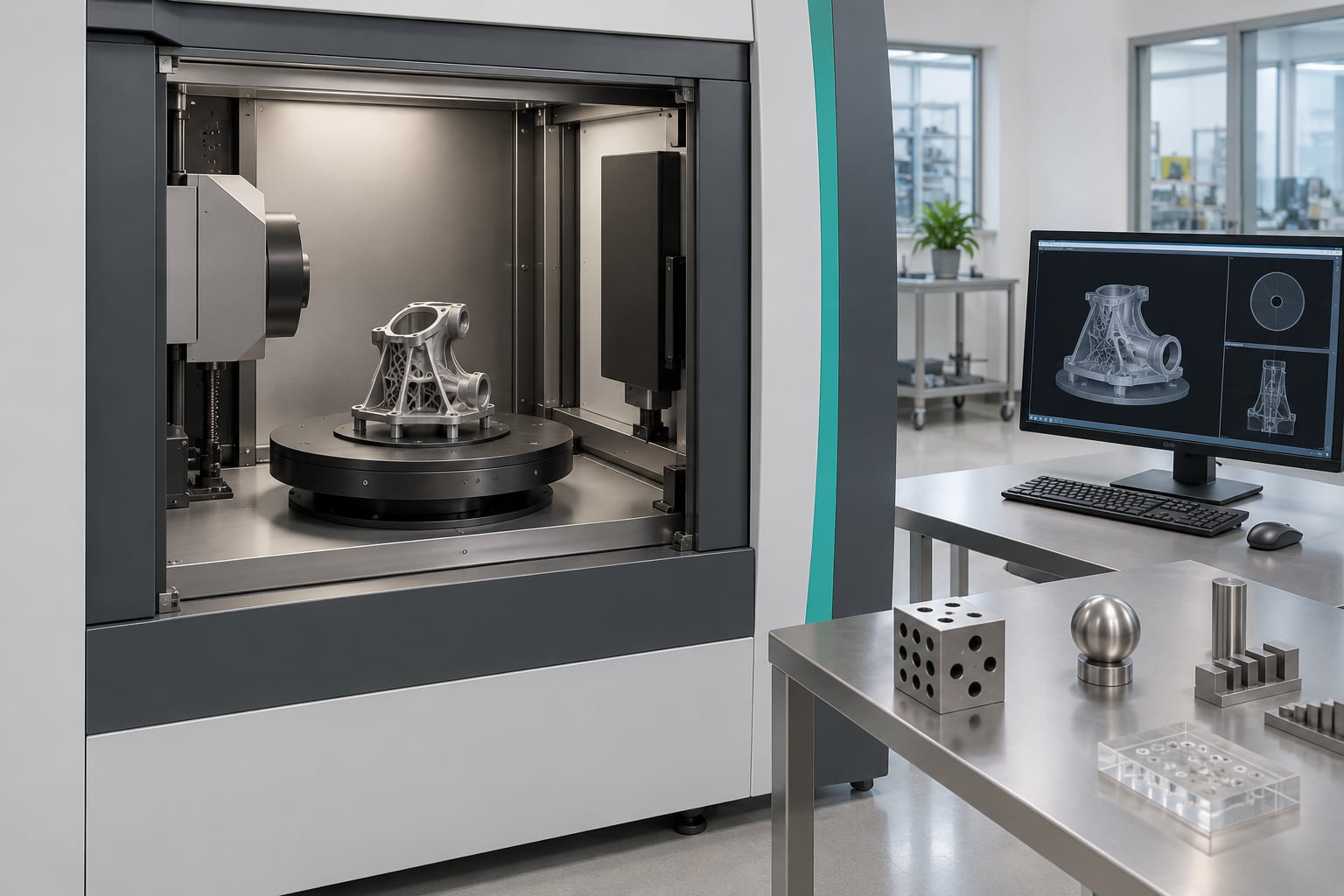
CT scanning for additive manufacturing quality control is the use of X-ray computed tomography, usually called CT or XCT, as a non-destructive inspection method. An X-ray source fires projections at the part from many angles while it rotates, a detector records each projection, and a reconstruction algorithm turns those 2D projections into a 3D volume made of voxels. You then segment that volume, isolate defects, and compare the actual shape against the nominal CAD geometry.
Two different jobs live inside that one technique, and keeping them separate saves a lot of argument later. Defect analysis asks where the voids are and how large they are. Dimensional metrology asks how far the real part sits from its CAD model, in millimetres and tolerances. A scanner set up for one is often the wrong configuration for the other, and mixing them tends to produce a report nobody can defend.
How CT scanning for additive manufacturing quality control differs from other methods
Visual and tactile inspection only see the outside. If the acceptance criterion is a surface finish or a visible crack, a magnifying glass and a bright light are faster and far cheaper than a scan.
Coordinate measuring machines and optical 3D scanners measure external geometry with micron-level accuracy, but they are blind to the interior. A CMM can confirm a part matches its drawing perfectly while a 0.4 mm void sits 6 mm below the skin.
Ultrasonic testing reaches deeper than CT in thick, dense parts and is faster on large aerospace components, but it needs a smooth, accessible surface and a geometry that does not scatter the beam. Complex lattice structures and thin walls defeat it.
Dye penetrant testing is excellent for cracks that break the surface and costs almost nothing. It finds nothing at all for a sealed internal void, which is exactly the defect type that matters most in a powder bed fusion part.
Why CT Inspection Matters for 3D-Printed Parts
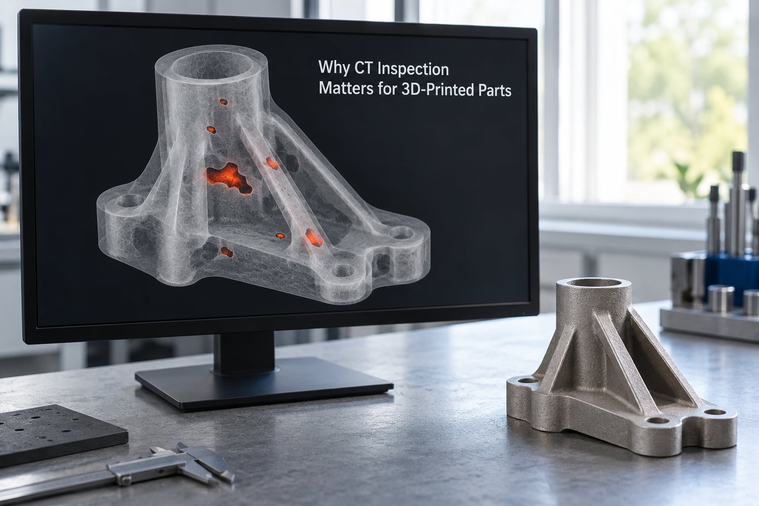
The defects that shorten the life of a metal printed part are usually internal, and the mechanisms that create them leave different signatures that CT can separate.
Gas porosity comes from entrained shielding gas during the melt, and it tends to be roughly round, scattered through the bulk, often near the as-built surface where spatter and re-melting occur.
Lack of fusion is a bonding failure between layers or between adjacent scan tracks. It is typically flat and irregular, it follows the layer direction, and it is a fatigue problem the moment it exists.
Keyhole porosity is essentially a lack-of-fusion defect at its most severe, forming when the melt pool collapses and re-solidifies rather than fusing. It is the defect most tightly correlated with energy input and scan strategy, and it is the one that ends a qualification build.
Inclusions come from the powder, the chamber, or recycled powder that has picked up contamination. Powder particles with internal voids propagate those voids straight into the printed part, which is one reason powder gets scanned before the build, not just after.
Cracks and delamination form from residual stress and steep thermal gradients. Cracks are thin and highly attenuating, so they show up well when they are oriented across the X-ray beam and badly when they run parallel to it.
Trapped or residual powder in closed cavities is the defect nobody catches with a surface check. An internal channel or a sealed lattice cell can hold un-fused powder indefinitely, and that powder becomes a debris source the moment a fluid or a mating part touches it.
Dimensional deviation from the CAD model is the other half of the job. Distortion from residual stress, over-melt on thin walls, and thermal effects near the plate edges all move the part away from nominal, and CT shows you the whole field at once instead of a handful of probed points.
What CT does not do is find every surface defect. A shallow surface-connected indication on an as-built face can sit below the resolution limit of a volume render, and many programs inspect as-built surfaces optically or by dye penetrant before or after the scan. CT also struggles to separate a crack from a tight inclusion when both are thinner than a few voxels.
CT Scanning for Additive Manufacturing Quality Control at a Glance
Here is the short version of what you are signing up for when you put CT into the plan.
| Aspect | What it means in practice |
|---|---|
| What CT measures | Linear attenuation reconstructed into a 3D voxel volume, reported as defect volume, defect count, wall thickness, or deviation from the CAD nominal |
| Defects it identifies | Gas porosity, lack of fusion, keyholes, inclusions, internal cracks, delamination, residual powder in closed cavities, wall-thickness loss |
| Typical parts | Metal LPBF, DMLS and SLM components, test coupons, lattice structures, medical implants, fuel-system and thermal hardware, multi-material assemblies |
| Part preparation | Remove loose powder, degrease and dry, fill internal channels with a contrast medium if they must be shown, mount in low-attenuation foam or on a fixture |
| Output | Voxel volume plus a report stating voxel size, source energy, projection count, threshold settings and measurement uncertainty |
| Resolution limit | Set by voxel size, which is driven by the part envelope, the material attenuation and the source and detector geometry |
| Main limitations | Beam hardening and scatter artefacts, partial-volume effects, threshold sensitivity, scan time, capital cost, awkward fixturing, multi-material interfaces |
| What it cannot replace | Surface finish measurement, mechanical testing, chemical analysis, and metallography for defect morphology |
How Does CT Inspect an Additive Manufactured Part?
A production CT inspection follows a fixed sequence. Deviating from it usually means chasing artefacts instead of defects.
- Define the objective. Decide before anything is measured whether you are doing defect analysis, dimensional metrology, or both. Each objective drives a different energy, magnification, voxel size and acceptance threshold.
- Prepare the part. Blow out or vacuum the loose powder, then ultrasonically clean and dry the part so residue does not read as an attenuation feature. Fill sealed internal channels with a low-viscosity contrast medium if you need the channel walls and any trapped powder to be visible.
- Fixture it. Mount the part in a foam or low-attenuation support so the material sits inside the beam path as centrally as possible. Off-centre placement costs contrast and resolution, and it is the single most common self-inflicted artefact.
- Set the acquisition. Choose source energy high enough to penetrate the thickest section of the part, then pick a voxel size small enough for the smallest defect you must detect. Increase projection count for fine features and for dense metals.
- Reconstruct. The projections are reconstructed into the volume, then corrected for beam hardening and scatter. This is where most of the scanning time goes, and it is the reason a smaller field of view is dramatically faster.
- Segment and analyse. Thresholding separates material from pore and inclusions. The analyst sets the threshold, checks it against known sound material in the same part, and applies a consistent rule across the dataset.
- Compare against nominal and report. Overlay the volume on the CAD model, run GD&T, map wall thickness, and export the defect list with voxel size, threshold and uncertainty attached. The report is the deliverable; the pretty render is not.
One thing worth knowing about step six: the manual version of this means scrolling through thousands of reconstructed slices looking for anomalies, which is slow and tiring and subjective. A published vendor case study from TEC Eurolab with BlueTensor reported roughly a 50 percent cut in operator analysis time when automated algorithms flagged anomalies for a trained operator to validate, with the operator still feeding periodic model retraining. That is the shape of the argument in most shops today: the software narrows the field, a qualified person still signs it.
What Types of CT Scanning Are Used for 3D Printing?
Four families show up in AM quality work, and they are chosen by part size and by how small a feature has to be resolved.
Micro-CT and nano-CT operate with a microfocus X-ray tube and a small field of view, typically delivering voxel sizes from about 1 to 20 micrometres. This is the tool for powder characterisation, small test coupons, extracted witness specimens and failure analysis. It is not a whole-part tool.
Industrial CT in a cabinet uses a higher-power tube, commonly running 160 to 450 kV, with a larger measurement volume and voxel sizes in the tens of micrometres. This is the configuration that inspects finished metal parts, because it balances penetration against resolution for a real component envelope.
MeV sources exist for very dense alloys and very large sections, where a standard tube simply cannot get usable photons through the part. If you routinely scan thick nickel superalloy hardware, you are in this category.
In-line or in-process metrology is the partial competitor and partial complement. Optical and fringe-projection methods measure the layer or part surface during the build or immediately after it, feeding a closed loop back into the process. They catch spatter, layer height deviation and distortion in real time, but they do not see inside.
It is worth separating the CT job types explicitly, because buyers routinely buy the wrong configuration for the goal.
| CT job | Primary output | What drives the configuration |
|---|---|---|
| Defect analysis | Defect location, size, count, volume fraction, morphology | Smallest defect of interest, penetration through the thickest section, threshold sensitivity |
| Dimensional metrology | Dimensions, tolerances, GD&T results against nominal | Voxel size against tolerance, geometric repeatability, calibration and traceability |
| Part-to-CAD comparison | Deviation map between as-built volume and nominal model | Registration accuracy, alignment protocol, resolution matched to the deviation band you care about |
| Reverse engineering | As-built geometry model for comparison or recovery | Resolution, coverage, and whether the output feeds a digital twin |
How Do You Choose the Right CT Resolution?
Choose the voxel size from the smallest defect you are contractually required to detect, then work backwards to see whether the geometry and material can deliver it. Asking a vendor for the best resolution on a part they have never seen is how people end up with a scan that cannot see the thing they needed.
Voxel size is set by the size of the field of view you need to cover divided by the detector resolution. Cover a whole part and the voxels get large. Cover only a critical region, sometimes called a scan region or local scan, and you can drop to a fraction of the voxel size for the same hardware.
Penetration comes next. Dense alloys attenuate hard, so the energy has to rise as section thickness rises, and every rise in energy costs resolution and contrast. Aluminium is forgiving. Nickel superalloys and thick steel sections are not.
A workable rule of thumb: you cannot reliably claim a defect smaller than roughly three to five voxels across, and you will see fewer false positives when the defect is more than about ten voxels across.
| Part situation | Typical industrial CT voxel size | Defects you can expect to resolve and quantify |
|---|---|---|
| Powder sample or small coupon, under 25 mm | 5 to 20 micrometres on micro-CT | Internal particle voids, powder packing, micro-porosity well under 50 micrometres |
| Thin-wall metal part under 60 mm across | 20 to 50 micrometres | Gas porosity, lack of fusion above roughly 100 micrometres, wall-thickness loss on thin features |
| Substantive metal component up to 250 mm | 50 to 120 micrometres on a cabinet system | Defects above roughly 200 micrometres, major lack of fusion, trapped powder, larger inclusions |
| Large or very dense hardware, heavy sections | 100 to 250 micrometres, or MeV source | Coarse defects, delamination, gross geometry, internal channel integrity |
Read those numbers as planning ranges, not a specification. The right way to settle it is to scan one known-good and one known-bad part from your own process at two voxel settings, and see which defects survive at the setting your budget can carry.
How Are CT Results Evaluated Against Print Quality Requirements?
A CT number only means something next to an acceptance criterion. Report porosity as a volume fraction with a stated uncertainty, or as the largest single defect in a defined region, and compare it against a threshold written into the drawing, the material specification or the customer contract.
Start from the drawing. Criticality zones matter more than global averages, so a fatigue-critical region should have its own threshold rather than inheriting an average over the whole part.
Then use the build data. Process capability on your own coupons tells you what your process actually produces, which is a much stronger basis for a threshold than a literature value copied from another machine.
Watch for as-built versus machined geometry. If machining will remove 1 mm from a face, porosity 2 mm below that face stops being relevant, and CT is a good way to confirm that before the material is cut away. The reverse is worse: CT can show you that a defect is buried just under the machined skin and will be exposed as a surface void.
State measurement uncertainty with every figure. Segmentation threshold choice alone can move a reported porosity percentage by a meaningful margin, and without an uncertainty figure two labs can publish different numbers for the same part and both be right.
Vocabulary comes from the ISO 52900 family, which standardises additive manufacturing terminology and process categories. Measurement and inspection practice is commonly tied to VDI/VDE 2634, and aerospace programmes tend to reference SAE 7032 and NASA-STD-6033 and NASA-STD-6035. Whatever the governing document, state it on the report.
For qualified measurement, the IQ, OQ and PQ cycle still applies. Installation qualification confirms the system arrived working, operational qualification confirms it performs across the range you need, and performance qualification confirms it performs on your parts, your material and your geometry. A CT report without that chain is a picture, not a measurement.
What Are the Limitations of CT for Additive Manufacturing Inspection?
CT is powerful, and it has a specific list of things it does badly. Knowing them saves you from buying a scan you cannot interpret.
Beam hardening and scatter artefact are the two big ones. Dense material absorbs low-energy photons preferentially, so the beam gets harder as it crosses the part, the reconstructed material reads inconsistently, and void volumes near thick sections get distorted. Scatter adds a haze around dense features that can look like a diffuse cloud of porosity that is not there.
Partial-volume effects matter at the small end. A defect that only partly fills one voxel does not reconstruct as a clean small void. It smears, and it can appear larger or smaller than reality depending on where it sits relative to the voxel grid.
Threshold sensitivity is the quiet accuracy problem. Segmentation is a binary decision applied to a continuous image, and moving the threshold a few percent can change a reported porosity figure noticeably. Two analysts can honestly disagree on a report.
Geometry fights fixturing. Very tall parts, deep thin channels and double-curved surfaces are hard to hold at a constant distance from the source and detector, and hard to place centrally. Parts with widely varying wall thickness also produce inconsistent contrast.
Multi-material interfaces are a known weak spot in the published literature, where dual-metal and multi-material builds produce attenuation changes that complicate interpretation of interfacial bonding quality.
Throughput and cost are real limits too. A scan is a physical process with a setup, a rotation, a reconstruction and a human review. For a low-volume, non-critical part, that cost is not recoverable by any argument.
Here is the decision view against the methods you would otherwise choose between.
| Method | Sees | Destructive | Weakness on AM parts |
|---|---|---|---|
| CT | Internal voids, inclusions, cracks, trapped powder, full 3D geometry | No | Resolution limit, artefacts, scan time, cost, awkward fixturing |
| Metallography | Defect morphology, lack-of-fusion shape, grain and phase detail | Yes | Destroys the part, only one plane, misses defects outside the section |
| Dye penetrant | Cracks and indications open to the surface | No | Cannot reach sealed internal voids, needs clean accessible surfaces |
| Ultrasonic testing | Internal flaws in dense material at depth, delamination | No | Needs accessible surfaces and simple geometry; struggles with lattice and thin walls |
| Industrial radiography | Internal flaws in one projection, cheap on large parts | No | Superimposed images, no depth or size, slow setup per part |
| Optical 3D scanning | External geometry and surface condition | No | No internal view, optical issues on shiny and rough surfaces |
| CMM | External dimensions and GD&T | No | Blind inside the part, no defect information at all |
| In-process metrology | Layer and surface deviation during and just after the build | No | Surface only, needs the machine to be instrumented and interruptible |
How Can Manufacturers Make CT Inspection More Cost-Effective?
CT cost scales with the volume you scan, the resolution you choose and the number of times you repeat it. Every one of those three is a decision you control.
Sample by risk, not by habit. Scan first articles, scan after any process change, scan a defined sampling fraction of production, and scan every part only where the consequence of a miss justifies it. A qualified part’s post-process inspection can account for more than half its total cost in some AM operations, so this is where the money is.
Scan representative regions, not whole parts. A local scan of the critical zone instead of the full envelope cuts voxel size and scan time at the same time. This is the highest-leverage move most teams never make.
Batch parts per load. A cabinet system with load automation can hold several parts at once. Fixturing for multiple parts takes longer to set up and shortens the queue dramatically.
Fix the acquisition once. Documented settings per part family, written by someone who did the work, stop people from rediscovering a workable recipe every time a part changes hands.
Automate the segmentation and keep the human. Automated analysis handles the volume of slices; a qualified operator sets the threshold, validates anomalies and signs the report. One documented case study reported about a 50 percent reduction in analysis time from that arrangement.
Stage the inspection. Development scans on coupons, process-qualification scans on witness specimens, and full scans on production parts at a defined frequency. Buyers who scan every part from day one waste money that would be better spent proving the process first.
Decide in-house versus outsourced honestly. A scanner makes sense when part volume is steady, turnaround matters to the customer, and there is someone qualified to run it. Below roughly a dozen scans a month with occasional peaks, outsourcing usually costs less and gives you access to higher energy and finer resolution than you could justify buying. When you outsource, ask for the voxel size, the uncertainty figure, the qualification chain and a sample report before you send anything.
And be candid about when to skip CT entirely. Low-volume, non-critical visual parts, or a process where you already have a validated coupon per build and a stable capability record, are better served by that coupon plus surface inspection. CT earns its cost where an internal miss means a scrapped build, a failed qualification or a field failure.
Frequently Asked Questions
What is CT scanning used for in 3D printing quality control?
CT scanning for additive manufacturing quality control images the inside of a printed part without destroying it. The reconstructed 3D volume is used to find and quantify porosity, lack of fusion, inclusions, internal cracks and trapped powder, and to compare the actual geometry with the CAD nominal. That gives you a repeatable internal measurement on every part rather than a pass or fail look at the surface.
What defects can CT scanning detect in additive manufacturing?
CT separates gas porosity from lack of fusion by shape and location, finds keyholes, inclusions from the powder or chamber, internal cracks and delamination, and residual un-fused powder sealed inside closed cavities or channels. It also maps wall thickness and deviation from the CAD model. It does not reliably find shallow surface-connected indications below a few voxels, which is why surface methods are often used alongside it.
Is CT scanning non-destructive?
Yes. Nothing is cut, sectioned or chemically altered during a scan, and the part can go straight to machining or assembly afterwards. That is the main reason CT replaces metallography on parts you cannot afford to destroy, such as first articles, qualification hardware and any part with a documented test history.
How long does a CT scan of a 3D printed part take?
A small coupon on micro-CT runs in minutes. A full metal component on an industrial cabinet system typically takes tens of minutes to a few hours, dominated by the projection count and the reconstruction rather than the rotation itself. Adding a local scan instead of a full envelope, and batching several parts per load, are the two changes that shorten the queue most.
What resolution CT scan is needed for porosity detection?
Work backwards from the smallest defect you must detect. A defect needs to span roughly three to five voxels to be resolved and ten voxels to be measured cleanly. That usually means 5 to 20 micrometre voxels for coupons, 20 to 50 for thin-wall parts under 60 mm, and 50 to 120 micrometres for components up to 250 mm across, with higher energy for denser sections.
What is the difference between CT scanning and metallography?
CT is non-destructive and sees the whole part in three dimensions, so it finds defects anywhere in the volume and gives locations and sizes. Metallography destroys the part and shows one polished plane in detail, including defect morphology, phase and grain structure that CT cannot resolve. In practice most shops run CT first to find the suspect region and metallography second to explain it.
Should I buy a CT scanner or outsource CT inspection?
Buy in-house when part volume is steady, turnaround affects your customer relationship, and you have someone qualified to run and interpret the system. Below roughly a dozen scans a month with occasional peaks, outsourcing usually costs less and gives access to higher energy and finer resolution. When you outsource, ask for the voxel size, the measurement uncertainty and the qualification chain before sending parts.
What standards apply to CT inspection in additive manufacturing?
ISO 52900 supplies the shared additive manufacturing vocabulary and process categories that reports should use. Measurement practice is often tied to VDI/VDE 2634, while aerospace programmes reference SAE 7032 and NASA-STD-6033 and NASA-STD-6035. Qualified measurement runs through installation, operational and performance qualification, and any porosity figure should carry a stated measurement uncertainty alongside it.
Conclusion
Write down the defects that can fail your part and the acceptance criteria for each before you look at any scanner. Then pick the smallest voxel size that can resolve the smallest of those defects through the thickest section of your material, and decide whether to scan coupons, witness specimens or production parts.
Everything else in this guide, the fixturing, the threshold, the uncertainty statement and the choice between CT and metallography, follows from those two decisions. Get them right and the scan becomes a measurement your quality plan can rely on instead of a set of images nobody can defend.