Heat treating 3D printed aluminum parts means raising the as-built part to a controlled temperature below its melting point, holding it there, then cooling it at a controlled rate to cut internal stress and, depending on the cycle, raise strength and hardness. Almost every metal additive process benefits, and the right route depends first on which alloy you printed and what property you actually need.
The laser in a powder bed fusion machine melts thousands of tiny spots per layer, and that rapid solidification is the source of both the problems and the potential. It locks in residual stress, leaves a fine cellular microstructure, and traps some gas. Heat treatment relaxes the first, restructures the second, and leaves the third mostly alone.
This guide walks through alloy selection, the three main cycle routes, preparation, the process controls that decide whether a part survives the furnace, cooling media, distortion control, and how to verify the result. The numbers quoted here come from published process windows and supplier property data. Your alloy supplier’s specification governs your parts, not a web page.
Table of Contents
- 1What Is Heat Treating 3D Printed Aluminum Parts?
- 2Which Aluminum Alloys Can Be Heat Treated?
- 3Alloys you will meet in metal 3D printing
- 4Why Heat Treat 3D Printed Aluminum Parts?
- 5How to Prepare Parts Before Heat Treatment
- 6Strip the part back to clean metal
- 7Degrease and dry thoroughly
- 8Measure and mark before the part moves
- 9Fixturing that supports rather than grips
- 10Heat Treating 3D Printed Aluminum Parts: Key Process Controls
- 11Solution treatment
- 12Quench
- 13Artificial ageing
- 14Atmosphere and ramp rate
- 15Furnace choice for small batches
- 16What Temperature and Time Are Required?
- 17How Does Cooling Affect Distortion and Properties?
- 18How Do You Minimize Warping, Cracking, and Dimensional Change?
- 19Design-side controls
- 20Process-side controls
- 21Inspect before and after
- 22How Do You Verify That the Heat Treatment Worked?
- 23Hardness
- 24Conductivity
- 25Dimensional and visual
- 26Mechanical testing
- 27Documentation
- 28Frequently Asked Questions
- 29Can heat treating fix poor layer bonding in a 3D printed aluminum part?
- 30Can heat treating 3D printed aluminum parts cause cracking?
- 31What aluminum alloy is easiest to heat treat?
- 32Should support marks be removed before heat treatment?
- 33Can a small workshop heat treat aluminum parts without an industrial furnace?
- 34Conclusion
What Is Heat Treating 3D Printed Aluminum Parts?
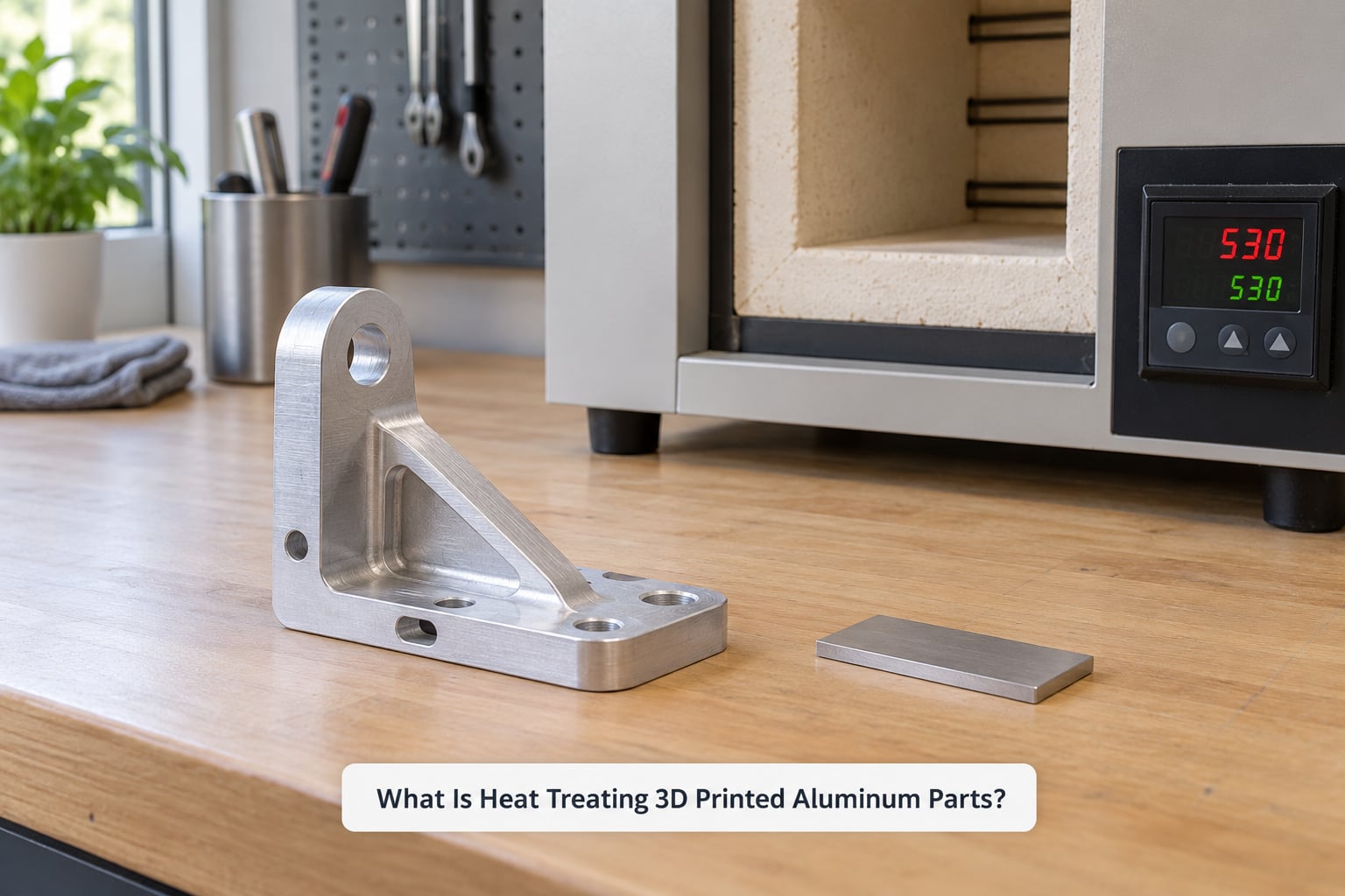
Heat treating 3D printed aluminum parts means heating the as-built part to a controlled temperature below its melting point, holding it there, then cooling it at a controlled rate to relieve internal stress and, depending on the cycle, increase strength and hardness. Nothing is melted and nothing is added. The part enters the furnace in exactly the shape it came out of the machine and leaves it in the same shape, ideally.
That last point matters more than people expect. Additive manufacturing is not casting or forging, so there is no traditional mill practice to lean on. Every cycle has to be written for the alloy, the printing route, and the geometry together.
A few terms get used loosely and it helps to separate them early. Residual stress is the internal force left in a part once the thermal gradients of printing or machining have passed. Stress relief is a low-temperature hold that lets that force relax without changing the microstructure much. Annealing is a hotter, longer cycle that softens the alloy back toward its most ductile state. T6 is a specific hardening route: solution treatment, quench, then artificial ageing.
Those four are not interchangeable. Asking for the wrong one is the single most common way a maker ends up with a part that is softer than before or bent out of tolerance.
Which Aluminum Alloys Can Be Heat Treated?
Only alloys that respond to precipitation hardening can be heat treated for strength. Aluminum-silicon-magnesium casting alloys such as AlSi10Mg (also sold as LM9, EN AC-43100 or A360) fall in that group, as do A357 and AlSi7Mg. Wrought alloys like 6061 and 7075 are heat treatable too, but not from a printed powder bed in any simple way.
The dividing line is composition, not the printer. An alloy with enough magnesium and silicon to form fine precipitates after ageing can be strengthened. An alloy without them cannot, no matter what you do in the furnace.
Alloys you will meet in metal 3D printing
AlSi10Mg is the default for most laser powder bed fusion work and by far the best documented for T6. Renishaw-derived process literature describes the standard route as solution treatment followed by artificial ageing.
AlSi12 and similar high-silicon casting alloys are more commonly used for binders, jewelry and low-demand parts. They are essentially non-heat-treatable, though a mild stress relief is often applied to reduce movement during finish machining.
A357 / AlSi7Mg sits between the two. It is age hardenable and is used where higher ductility than AlSi10Mg is wanted.
6061 and 7075 are common on paper and awkward in practice. Both need rapid solutionizing to hold supersaturation, which a batch furnace with slow cooling cannot deliver for a thick printed part, and 7075 is famously crack-prone when laser powder bed fusion is combined with any of this.
Scalmalloy, a scandium-modified aluminum-magnesium alloy, is used where strength-to-weight beats ductility. Scan the specification carefully; the ageing window is narrower than for AlSi10Mg and overshooting can coarsen the precipitates you paid for.
If you printed with binder jetting and infiltrated the part with a separate alloy, treat it as two materials. The heat treatment belongs to the infiltrant, not to the printed skeleton.
Why Heat Treat 3D Printed Aluminum Parts?
Heat treatment is worth doing on a printed aluminum part when you need repeatability, not just strength. As-built properties scatter widely between builds and between orientations, and that scatter is usually larger than the difference between an as-built part and a properly treated one.
The realistic gains, in rough order of how often they matter:
- Reduced residual stress. This is the big one. A stress-relieved part is far less likely to move when it is machined, and much less likely to crack at a hole or a fillet afterwards.
- Higher tensile and yield strength. Published T6 AlSi10Mg data puts ultimate tensile strength in the 220-340 MPa range and yield strength at 180-280 MPa, depending on build orientation and test standard.
- Higher hardness and better wear resistance on machined surfaces.
- Better fatigue behaviour than as-built material, mostly because the surface and internal defect population stop being dominated by unmelted powder boundaries.
- Dimensional stability. A relieved part holds tolerance through later handling, shipping and assembly.
Now the limits, because they matter just as much. Heat treatment does not close gas porosity, does not repair a delaminated or poorly bonded layer, and cannot fix a geometry that was already outside tolerance. It will not improve surface roughness. A part that failed a leak test as-printed will not start passing one after a furnace cycle.
How to Prepare Parts Before Heat Treatment
Preparation is where most of the avoidable failures happen. A part with trapped support material, a plating bath residue or a solvent film can come out of the furnace damaged, and you will not know it was your fault rather than the cycle’s.
Strip the part back to clean metal
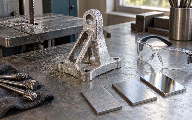
Remove every support, including the interface layer, and grind or machine the witness marks flush. Support material is often a different, softer alloy or a filled binder that either melts, sinters onto the part or reacts with the atmosphere.
Take the surface finish down to bare metal where you can. An as-printed surface carries unmelted powder, and that powder plus a full solution cycle is a reasonable way to grow surface porosity.
Degrease and dry thoroughly
Wash away cutting fluid, finger oils, marking dye and any plating or anodize residue. Solvents leave films that flash into toxic fume at temperature, and a bath-processed finish can blister or outgas badly. Rinse, then dry fully.
Measure and mark before the part moves
Photograph the part, record every dimension you care about, and write the alloy, print orientation and batch on it. A laser engrave or a stamped tag is better than a paper label, which does not survive the cycle. You want to know what the part looked like before when you measure it after.
Fixturing that supports rather than grips
Support the part at its stiffest features, on sacrificial tabs if you can machine them off later. Do not clamp on a functional wall. Fixtures should hold position through the quench, not resist the thermal contraction that is about to happen, and sacrificial stainless or tool-steel carriers keep aluminum out of contact with anything that could gall.
On safety: metal powder parts have sharp support witness marks and cut edges, and gloves are not always the right answer when you are lifting a heavy part into a furnace. Gloves for handling cold sharp parts, face protection for anything that could spall, and a ventilation plan you have actually thought about.
Heat Treating 3D Printed Aluminum Parts: Key Process Controls
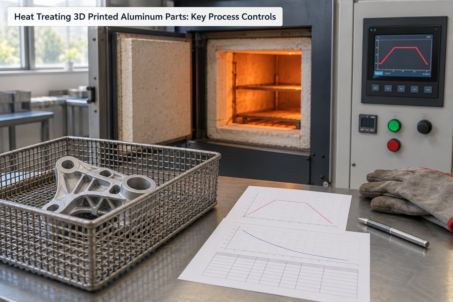
Every cycle is the same four decisions: what temperature, how long, in what atmosphere, and how fast it comes down. Temperature and time come from the alloy specification. Atmosphere and cooling come from the alloy, the geometry and what you are willing to risk.
Solution treatment
Hold the part long enough and hot enough to dissolve the strengthening precipitates and the silicon-rich phase into a solid solution. Below that window you get partial treatment and a property you cannot repeat. Above it, and above the solidus for some alloys, you start melting the lowest-melting constituents and the part loses its shape permanently.
Quench
Pull the part from the furnace and cool it fast enough to trap the supersaturated solution. The transfer has to be quick, the medium has to wet the surface immediately, and the quench has to be big enough that it does not boil away locally. Quench delay is the variable people leave out, and it is the one that most reliably wrecks an otherwise correct cycle.
Artificial ageing
Reheat to a lower temperature and hold long enough for fine precipitates to form and grow. This is where the strength actually comes from. Under-ageing leaves strength on the table; over-ageing coarsens the precipitates and gives them back.
Atmosphere and ramp rate
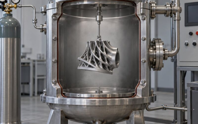
Aluminum is easy to oxidize and it does not care about your schedule. Furnaces used for this work run under inert argon, either as a partial vacuum, in the region of 3-300 torr, or as a positive atmosphere at roughly 760-1100 torr; higher-end vacuum furnaces quote 10-4 to 10-5 torr. Debinding and sintering cycles sit lower still, around 3-30 torr.
Ramp rate is slower than most people expect, and for a good reason: a thick printed part heats unevenly, and a fast ramp just reproduces the thermal gradient that created your residual stress in the first place. Ramp uniformly, soak long enough for the thickest section to reach temperature, and record the ramp and soak as part of the part’s history.
Furnace choice for small batches
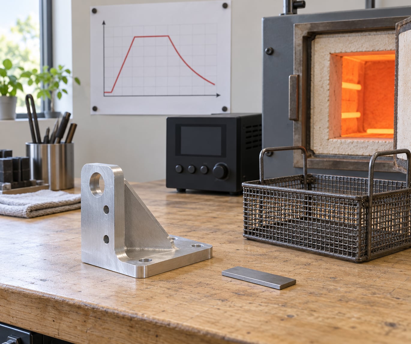
Small shops get along with a tube furnace for stress relief and a chamber furnace with argon backfill for anything involving a quench. Vacuum furnaces give the best control and the worst capital cost. Hobbyists in the metal printing communities do build small refractory-lined furnaces, and a thread on the gt40s forum describes a cut-down drum with ceramic mat heaters used for field heat treating. That works for stress relief. It is not a route to a qualified T6 cycle.
What Temperature and Time Are Required?
The windows below are typical published ranges for reference, not a prescription. Nominal temperature, part thickness, furnace uniformity, load size and your alloy data sheet all move the final schedule, and the data sheet wins every time.
| Cycle stage | Typical range | Notes |
|---|---|---|
| Stress relief (as-built or machined) | 300-400 °C | Short hold, slow cool. Raises stress-relieved strength only slightly; does not age the alloy. |
| Solution treatment (AlSi10Mg T6) | Above 500 °C, hold 4-12 h | Must not exceed 550 °C. Above the solidus the alloy begins to melt and the part is lost. |
| Quench | Immediate on removal | Water or polymer melt. Transfer time between furnace and medium is a controlled variable. |
| Artificial ageing (AlSi10Mg T6) | 155-165 °C, 6-24 h | Longer holds at the low end of the temperature range give the most stable result. |
| Full anneal | Alloy dependent, soak hours | Softens for forming or machining. Properties drop well below as-built strength-hardened values. |
Published T6 results for AlSi10Mg land at 220-340 MPa tensile and 180-280 MPa yield. Published work also reports ultimate tensile strengths above 400 MPa from stress-relief-only cycles in the 300-400 °C range, which is worth knowing: the property you get depends as much on the build orientation and the test method as on the cycle.
Wrought alloys follow different logic. 6061-T6 is solutionized in the 530-545 °C range and aged around 175-190 °C; 7075 is solutionized near 470-490 °C with a T6 age near 120 °C extended for many hours. Those are wrought numbers, and a printed 7075 part in a batch furnace is a research project rather than a routine job.
How Does Cooling Affect Distortion and Properties?
Cooling rate is the trade-off. Faster cooling locks in more strength, but aluminum contracts roughly twice as much as steel, and a part that cools unevenly bends. Water quenches hardest and distorts most; air cools gentlest and leaves the most residual stress and the least strength.
Water is fast, inexpensive and effective for thin, simple parts. It also distorts thin features badly and can quench-crack complex geometry.
Polymer quench — typically a molten polymer bath — is slower than water but far more uniform, and it is the usual choice when distortion matters more than the last few percent of strength.
Air or forced gas is enough for stress relief and for anneals, and for parts where dimensional stability is the whole point. It will not develop a T6 condition on its own.
Oil works on aluminum but adds a fire risk with hot parts and the handling that implies. It is a controlled industrial environment, not a workshop default.
Two controls do more than the choice of medium. First, quench delay: the seconds between leaving the furnace and entering the medium have to be consistent, and any variation shows up as variation in hardness across the load. Second, fixturing: support the part at several points so that when it shrinks it has nowhere to pull against, and let it contract rather than clamping it rigid.
Large sections cool slower than small ones no matter what you do, so a mixed-thickness part will not respond uniformly. Sometimes the honest answer is a slower cooling route and accepting lower strength.
How Do You Minimize Warping, Cracking, and Dimensional Change?
Warping after heat treatment is almost always thermal, and it is usually decided before the part ever reaches the furnace. By the time you see it, the geometry, the orientation and the support strategy have already done most of the damage.
Design-side controls
- Keep wall thickness uniform. A part that steps from 2 mm to 8 mm has two different contraction paths and will bow.
- Avoid long unsupported spans and thin cantilevers. Add ribs or thicken locally rather than relying on a fixture.
- Balance the section around the centre of mass so contraction has a symmetric path.
- Place holes, threads and sealing faces so that a small amount of movement does not destroy a fit. Machine critical features after treatment, not before.
- Leave a machining allowance where tolerance is tight, then cut it after the cycle.
Process-side controls
- Stress relieve in the as-printed or immediately post-machined state, then do the heavy machining, then age. Splitting the cycle this way reduces the load the final quench sees.
- Ramp slowly and soak for the thickest section, not the average one.
- Fix the quench delay and the medium and record both.
- Choose polymer quench over water for thin-walled or long parts; choose air over water for parts whose geometry is complex.
- Handle quenched parts with support tooling, not by a thin wall. They are hot, soft and full of locked-in stress.
Inspect before and after
Take a set of measurements and photographs before the cycle and the same set after. If a part moves, you need to know whether it moved during the furnace or whether you mis-measured it as-printed. Cracks that appear after treatment usually started as flaws in the build, so a low-magnification surface inspection before and after is cheap insurance.
How Do You Verify That the Heat Treatment Worked?
Verify with more than one method, because no single check catches every failure. Surface hardness alone tells you very little about the core of a thick part, and conductivity tells you about the whole part but not which cycle you ran.
Hardness
Brinell or Rockwell on machined surfaces is fast and cheap, and it is the everyday check. On an as-built surface the readings are unreliable because the indenter lands on unmelted powder and a cellular structure. Use coupons or machined pads.
Conductivity
An eddy-current conductivity test is a good proxy for how much precipitation occurred. It is non-destructive, it samples a lot of material, and it correlates with the structural change rather than with hardness alone.
Dimensional and visual
Compare against your pre-treatment measurements on the features you care about, and look for surface blistering, oxide whitening, and cracks at fillets and holes.
Mechanical testing
Tensile coupons machined from the build, or from witness coupons placed in the same load, are the only way to know what the material is actually doing. Suppliers who publish property tables, such as Protolabs for stress-relieved AlSi10Mg, get their repeatability from running test bars with every build.
Documentation
Keep the cycle record, the alloy certificate, the print parameters, the quench medium and delay, and the inspection results for every treated part. For aerospace and medical work the specification is usually AMS 2750 for pyrometry, with Nadcap accreditation for the heat-treat source, and the furnace calibration records become the part record. Small shops rarely need that, but building the habit early costs nothing.
Frequently Asked Questions
Can heat treating fix poor layer bonding in a 3D printed aluminum part?
No. Heat treatment changes microstructure and residual stress, not the geometry of a bond. If layers failed to melt into each other during printing, the gap between them survives the furnace and usually opens up further. Unmelted powder, lack of fusion and delamination need to be solved in the print parameters or by redesigning the part, not with a longer soak. Inspect the suspect area first, because a cycle will usually make a marginal bond fail visibly rather than quietly fix it.
Can heat treating 3D printed aluminum parts cause cracking?
Yes, and the usual cause is geometry rather than temperature. Rapid quenching, a long transfer delay, a part with abrupt section changes or thin walls, and clamping a part so it cannot contract all push in the same direction. Over-ageing at too high a temperature or too long a hold coarsens precipitates and reduces ductility, which makes cracking more likely later in service. Support the part, keep quench delay consistent and check the cycle against your alloy specification.
What aluminum alloy is easiest to heat treat?
AlSi10Mg is the easiest in practice because it is the default alloy for laser powder bed fusion and its cycle is the most documented. Published process windows put solution treatment above 500 degrees Celsius but never above 550, followed by a water or polymer quench and artificial ageing at 155 to 165 degrees Celsius. The cast-equivalent A357 and AlSi7Mg families also respond well. High-silicon non-age-hardenable alloys cannot be strengthened this way at all.
Should support marks be removed before heat treatment?
Yes. Support structures and their interface layers are usually a different composition or a filled binder, and they can melt, sinter onto the part or react badly in the furnace atmosphere. Take the part back to clean metal and grind the witness marks flush before the cycle. Leaving them in also traps unmelted powder and residue in the rough zone, which can grow into porosity during solution treatment. Budget the machining time, because the same pass is a good moment to add your finishing allowance.
Can a small workshop heat treat aluminum parts without an industrial furnace?
For stress relief, yes, and metal printing hobbyists do build small refractory-lined furnaces for exactly that, including a cut-down drum with ceramic mat heaters described on the gt40s forum. For a T6 cycle the requirements are harder: argon control, reliable thermocouple pyrometry, a fast and repeatable quench with a controlled delay, and enough thermal mass that the load does not cool before the part reaches the medium. For anything load-bearing, send it to a heat treatment service and ask for the cycle record.
Conclusion
Start by identifying the alloy and the property you actually need, because that decides between stress relief and T6 in one step. Then read the material data sheet, confirm the printed part is sound and free of support residue, design the fixture and pick the quench medium before the part is in the furnace, and record measurements before and after.
Heat treating 3D printed aluminum parts is routine once you treat the cycle as a written process rather than a hot oven you put things in. The metallurgy is well behaved; it is the undocumented variables that cost you parts.