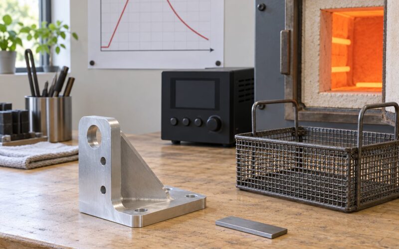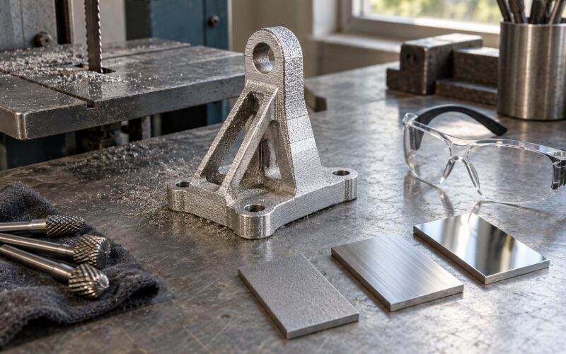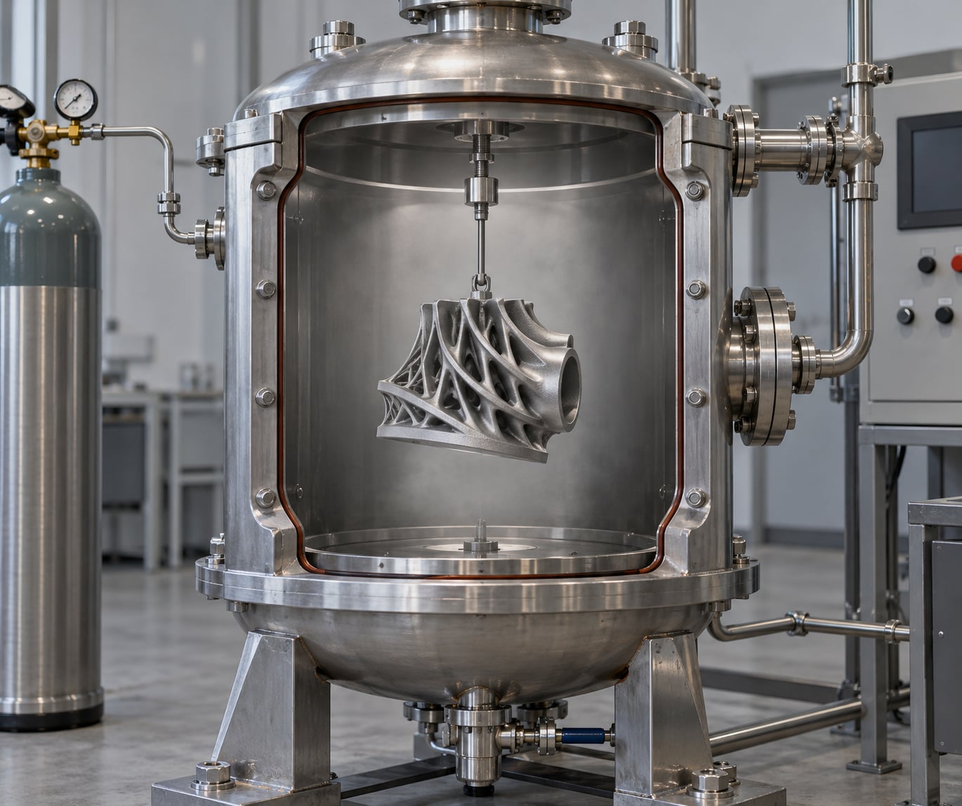
Hot isostatic pressing for printed metal parts is a post-processing step that heats a metal part inside a sealed vessel and floods it with pressurised argon, roughly 2,000 bar, from every direction at once. Internal gas pores and lack-of-fusion voids collapse, diffusion-bond to the surrounding metal and disappear, pushing relative density above 99.9%. It is the standard fix for porosity in safety-critical parts, and it is not a universal fix.
The catch is that HIP only closes voids sealed inside metal. Anything the argon can reach, it will enter instead of compressing. That single fact shapes almost every decision an engineer makes before booking a cycle.
Table of Contents
- 1What Is Hot Isostatic Pressing for Printed Metal Parts?
- 2Why Close Internal Voids in Additively Manufactured Metal?
- 3How Does the Hot Isostatic Pressing Process Work?
- 4How hot isostatic pressing for printed metal parts works
- 5What Materials and Printing Processes Use HIP Most Successfully?
- 6What Changes in Density and Mechanical Properties?
- 7When Is HIP Not the Right Choice?
- 8What Should Engineers Consider Before Ordering HIP?
- 9How Does HIP Compare With Other Densification Methods?
- 10How Can You Verify That HIP Worked?
- 11Frequently Asked Questions
- 12Does hot isostatic pressing make 3D-printed metal parts fully dense?
- 13Can HIP repair a metal part with visible or surface-connected porosity?
- 14How much does a metal 3D-printed part change after HIP?
- 15Is HIP performed on titanium, aluminum, steel and nickel alloys?
- 16Do you need to machine a metal part before or after HIP?
- 17How do you tell whether HIP successfully closed internal voids?
- 18Conclusion: What to Do First
What Is Hot Isostatic Pressing for Printed Metal Parts?
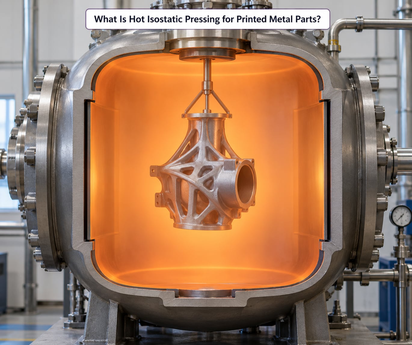
Isostatic means equal pressure in all directions, which is what separates HIP from every other densification method. Uniaxial pressing squeezes a part along one axis only; HIP surrounds it with a fluid that transmits pressure evenly to every surface, including surfaces no tool can reach inside a complex internal channel.
In metal additive manufacturing, HIP takes a part that is already geometrically correct but internally porous and makes it essentially solid. Common services describe the envelope as up to about 2,000 bar and 1,450 °C in an inert argon atmosphere, though practical printed-part recipes run far cooler than the machine limit.
For printed metal specifically, the defects it targets are closed internal voids: entrapped gas from the melt pool, keyhole porosity from unstable powder melting, and lack-of-fusion gaps between layers that never fully bonded. Each one is a stress concentrator sitting below the surface.
Two routes exist. Direct HIP places the part in the vessel as printed and relies on surface oxide or a thin encapsulation to retain internal gas. Can or retort HIP seals the part inside a welded or machined steel can, evacuates the air from the cavity and puts the whole can under pressure. Direct HIP is cheaper per part; can HIP buys you control over the internal atmosphere, which matters for reactive alloys.
Why Close Internal Voids in Additively Manufactured Metal?
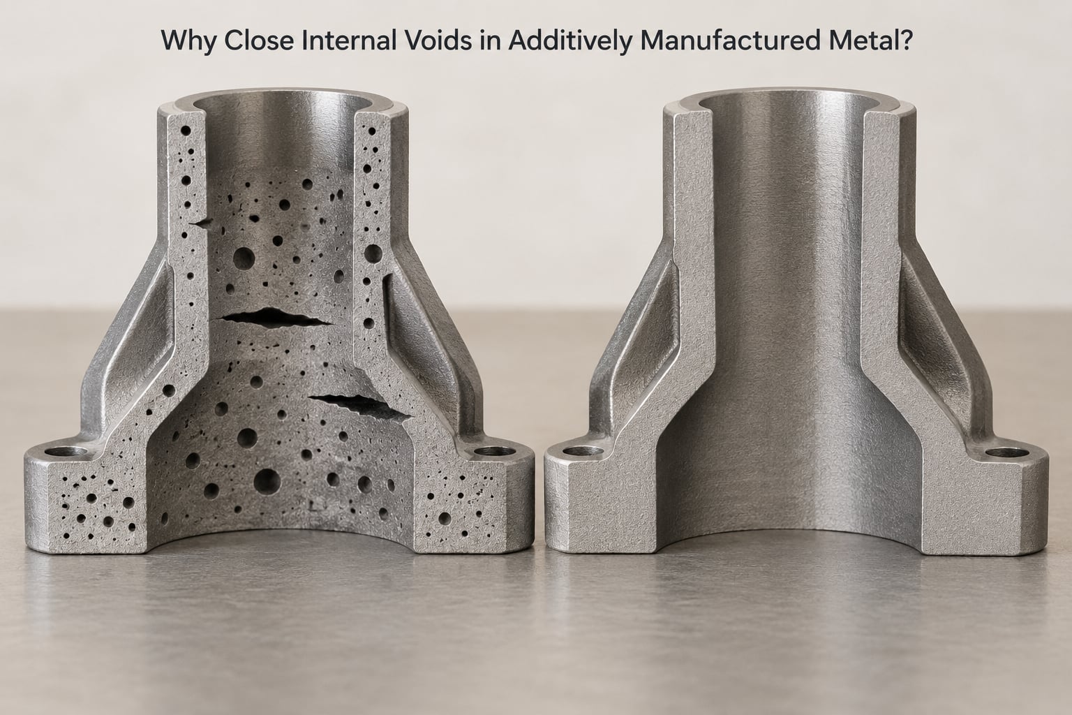
Metal powder bed fusion melts layer by layer, and every layer creates a new chance for a trapped defect. Gas entrained in the powder or generated by the melt pool has nowhere to escape, so it freezes into a near-spherical pore. Where the energy density drops, the powder fails to fuse and you get a flat, irregular gap instead.
These voids rarely show on the surface. A part can look perfect under a microscope at the skin and still carry a field of subsurface pores through its whole section, which is exactly why surface inspection is not evidence of internal quality.
The damage is disproportionate to the void size. Fatigue failure in metal is driven by stress concentration at crack-initiation sites, and a 0.1 mm pore in a high-cycle fatigue part can cut life by an order of magnitude compared with fully dense material of identical nominal strength.
Static tensile tests are far more forgiving. A part with 1% porosity may still pass a tensile strength spec, which is precisely why internal voids stayed a problem for years: they were invisible to the tests most shops ran. Fatigue-critical work, and any certification regime that asks for CT or ultrasonic evidence, exposes them.
How Does the Hot Isostatic Pressing Process Work?
How hot isostatic pressing for printed metal parts works
The mechanism is two-part. Heat takes the alloy above the point where it can creep and flow plastically, and the surrounding pressurised argon forces that material into every closed void. Atomic diffusion then bonds the newly opposed surfaces together, so the pore is not merely reduced but removed as a boundary.
Because the pressure is hydrostatic and uniform, there is no stress gradient through the part. Every point experiences the same conditions, which is why HIP produces near-isotropic results even when the printing process left the part anisotropic.
Here is the cycle as it typically runs:
- Depowder and clean. Trapped powder is removed by blasting, vibratory or ultrasonic cleaning. Residual powder left inside a channel can sinter into a hard lump that will not come out later.
- Stress relieve. Many shops anneal first to cut residual stress before the part ever sees pressure, which reduces distortion risk in step 6.
- Seal or encapsulate. Either weld a can around the part and evacuate the cavity, or apply the surface treatment that lets direct-HIP parts retain their internal gas.
- Load the vessel and purge. The vessel is evacuated, then filled with high-purity argon and brought to pressure. Oxygen in the gas is a real concern for titanium.
- Heat and pressurise. Temperature and pressure ramp together to the recipe. Pressure must never peak before temperature, or the cold part takes a shock load it cannot absorb.
- Hold under pressure. The hold is where densification happens. Slow furnace cooling follows unless the alloy benefits from fast cooling.
- Cool and open. Cooling happens under full pressure, because a void only stays closed while the medium outside it is denser than the gas inside. Part is removed, the can is cut off.
- Inspect and machine. Dimensional check, NDT, then machining to final size with the shrinkage allowance already built into the design.
Cycle time is dominated by the thermal mass of the vessel, not by the part. Small parts in a large vessel can run 8 to 16 hours end to end, and large assemblies with slow heating and cooling phases take considerably longer. The pressurised hold itself is often only two to four hours of an eight-hour-plus run.
What Materials and Printing Processes Use HIP Most Successfully?
Ti-6Al-4V is the classic case, particularly for aerospace brackets, fittings and implant parts printed by laser powder bed fusion. The alloy HIPs cleanly, and the resulting fatigue improvement is large enough to justify the cycle on its own.
Maraging steel and 316L stainless behave similarly. Maraging steel gains full density and a favourable transformation from as-built martensite to a coarser, tougher structure, at the cost of some hardness. 316L is widely HIPed because its common service is fatigue-loaded valve and pump hardware.
AlSi10Mg is harder. Cooling rates matter more than the porosity does, and a furnace cycle long enough to close pores can coarsen the silicon network enough to cost ductility. Fast cooling at higher pressure is the usual answer.
Nickel superalloys and refractory metals respond well because they are normally processed under pressure anyway, so HIP parameters overlap with existing powder metallurgy practice. Steels and tool steels reach 99.9% or better routinely; ceramics such as silicon carbide and silicon nitride push equipment to its temperature and pressure limit and shorten furnace life.
On the process side, laser powder bed fusion and electron beam melting produce the closed gas porosity that HIP targets most effectively. Directed energy deposition depends more on single-track quality, so HIP helps less. Binder jetting is the standout: the green part has large connected porosity and cannot reach full density by sintering alone, which makes HIP close to mandatory rather than optional.
What Changes in Density and Mechanical Properties?
| Property | As printed | After HIP | What drives the change |
|---|---|---|---|
| Relative density | Typically 95-99% | Above 99.9%, often 99.97% | Closure of all closed internal voids |
| Internal porosity | Gas pores and lack-of-fusion gaps | Below the level most CT systems resolve | Pressure-driven plastic flow and diffusion bonding |
| Fatigue life | Highly scatter-prone, crack initiation at pores | Large improvement, far less scatter | Fewer initiation sites, smoother surface |
| Ductility and fracture toughness | Low, void-driven | Noticeably higher | Removal of internal crack initiators |
| Tensile strength | Near wrought levels | Often slightly lower in Ti-6Al-4V | Coarser grains from the long hold at temperature |
| Residual stress | Significant after printing | Substantially reduced | Creep and stress relaxation at temperature |
| Anisotropy | Layer-direction dependent | Greatly reduced | Uniform pressure and a transformed microstructure |
| Surface finish | As-built Ra from the print | Unchanged | HIP acts on the interior only |
| Dimensions | As-built tolerance | Shrinkage on the order of 1-3% | Densification and thermal contraction |
Read that table carefully before you promise anyone anything. HIP does not hand you the same tensile numbers with better fatigue. In Ti-6Al-4V the microstructure often transforms to a coarser lamellar alpha-beta structure, which trades static strength for ductility and toughness, so a printed part qualified on tensile alone may need requalification after HIP.
Two things HIP never touches: the outer surface, which still carries the print’s roughness and any surface-connected defect, and the overall envelope, which shrinks as the material densifies. Plan a machining allowance for that shrinkage or your finished part will come out undersize.
When Is HIP Not the Right Choice?
This is where a lot of quotes get wasted. HIP fails, or fails to be worth it, in a predictable set of cases.
- Surface-connected porosity. Pressurised gas flows straight into an open pore. There is nothing to compress, so nothing gets closed. Surface defects need machining, welding or a surface treatment.
- As-built density already above roughly 99.5% with no fatigue case to solve. There is little left to close and the cycle cost buys nothing.
- Powder contamination or oxide inclusions. HIP closes the gap around an inclusion, it does not remove the inclusion. Foreign particles can also be driven to the surface.
- Sandwich and mesh-core structures. The internal architecture collapses under full pressure. This is the clearest hard no in the whole process.
- Lattice cores and sealed internal cavities. Trapped gas expands against an outside pressure that cannot get in to balance it, and the core crushes or the cavity wall bulges.
- Thin walls and long internal channels. Isotropic contraction shows up as distortion and bowing, and it is the distortion practitioners on research forums worry about most before committing a thin-walled part.
- Aluminium where ductility matters more than fatigue life. Grain coarsening during the hold costs more than the densification gains.
- Large parts on a tight schedule. Vessel size and thermal mass drive lead time, and if the part does not justify the queue, machining from billet wins on cost and time.
What Should Engineers Consider Before Ordering HIP?
- Name the alloy and the microstructural cost. Confirm what the microstructure becomes after the cycle and whether your spec survives it.
- Decide what defect you are fixing. Internal closed voids respond to HIP. Anything open to the surface or mechanical damage does not.
- Define the inspection standard first. Aerospace, medical and energy work carries its own qualification regime. Know whether CT, ultrasonic testing or coupon data is required before you pick the vendor.
- Check vessel capacity and envelope. A part that fits the machine envelope physically still has to clear the ports, and the vessel must reach your temperature and pressure together.
- Ask about gas quality and cooling. For titanium, high-purity argon and monitored oxygen content are non-negotiable. Fast cooling is worth paying for on aluminium and some steels.
- Plan depowdering and stress relief order. Powder removal has to happen first, and stress relief before HIP usually buys better dimensional stability.
- Build in the machining allowance. Plan for shrinkage of roughly 1-3% and re-verify by measuring the first article rather than trusting the number.
- Control distortion. Decide on fixturing or racking for thin sections, and agree how distortion is judged before the cycle runs.
- Confirm certification. For quality-regulated work, check for ISO 9001, AS9100 or ISO 13485 scope, and for NADCAP where the customer requires it.
- Price the whole route, not the cycle. HIP, can fabrication, machining, inspection and the queue time all belong in the number. Ask for the full lead time.
How Does HIP Compare With Other Densification Methods?
| Method | Pressure direction | Closes internal voids | Tooling | Part size limit | Relative cost | Result |
|---|---|---|---|---|---|---|
| HIP | Uniform, all directions | Yes, closed voids only | Can or encapsulation | Limited by vessel size and thermal mass | High | 99.9%+ density, isotropic, fatigue life up sharply |
| Uniaxial hot pressing | One axis, via dies | Partly, if the part can be pressed | Heavy graphite or metal dies | Small, geometry-limited | Medium | High density but directional properties, restricted shapes |
| Pressureless sintering | None, surface tension only | No, only open porosity | None | Large | Low | Consolidation without full density; typical of binder jetting pre-HIP |
| Stress relief or heat treatment | None | No | None | Unlimited | Low | Residual stress relief, some microstructural change, no densification |
| Sinter plus HIP | Uniform, all directions | Yes | Sinter fixture plus can | Vessel limited | High | The standard route for binder jetted and MIM parts |
The pattern is clear. Pressureless sintering and heat treatment are cheap and complementary, not substitutes. Sintering gives a part strong enough to handle, HIP finishes the job, and stress relief is often worth running on its own when the part is not fatigue-critical and the budget is tight.
How Can You Verify That HIP Worked?
Start with the cheapest test that can fail the part, then work up. X-ray radiography is fast but low resolution on small pores, and metallography is destructive and tells you about one location only.
Computed radiography and CT scanning are the tools the qualification regimes actually ask for. They find closed voids that every other method misses, and CT gives you a density distribution rather than a pass or fail on one location. The limitation is resolution: a scan that resolves 50 µm features will not see a 20 µm pore, so agree the defect size you are qualifying against before the scan rather than after.
Ultrasonic inspection is the traditional answer for larger components, and it works on dense, fine-grain material. As-built roughness and residual porosity can degrade the signal, which is another reason to inspect after HIP rather than before.
Metallography on witness coupons from the same vessel load gives you the microstructure evidence, including whether the alpha-beta morphology in titanium went lamellar as expected. Archimedes or immersion density measurement is quick but gives a bulk average and will happily hide a locally porous region.
Dimensional inspection is the check most often skipped. Compare the as-printed part, the HIPed part and the drawing, and use the first article to calibrate the shrinkage allowance for the production run.
Where fatigue life is the design driver, run mechanical testing on material from the same load rather than trusting a handbook figure. Tensile coupons are standard; fatigue coupons are slow and expensive, which is exactly why the density evidence matters so much in the certification file.
Frequently Asked Questions
Does hot isostatic pressing make 3D-printed metal parts fully dense?
It closes every void sealed inside the metal, which typically takes relative density above 99.9% and often into the 99.97% range. It does not close porosity that connects to the surface, because pressurised argon flows into an open pore instead of compressing it. Surface defects still need machining or another treatment.
Can HIP repair a metal part with visible or surface-connected porosity?
No. Gas under pressure enters an open pore rather than collapsing it, so surface-breaking defects survive the cycle untouched. A part with visible pits, keyholes or unmelted powder at the skin has to be machined, re-melted or re-sintered first. HIP only works on voids fully enclosed by solid metal.
How much does a metal 3D-printed part change after HIP?
Expect shrinkage on the order of 1-3% as the material densifies and cools, plus whatever distortion the geometry picks up from uniform contraction. Thin walls and long internal channels bow more than solid sections do. Always machine a first article, measure the actual change, and use that to set the allowance for production.
Is HIP performed on titanium, aluminum, steel and nickel alloys?
All four, routinely, with very different recipes. Titanium, maraging steel, 316L and nickel superalloys HIP cleanly. Aluminium is trickier because furnace cooling coarsens the microstructure, so fast cooling at higher pressure is usually preferred. The alloy determines the temperature, pressure, hold and cooling route you pick.
Do you need to machine a metal part before or after HIP?
For fatigue-critical and certified work, machine after HIP so the final surface and dimensions are verified on densified material. Leave enough stock for roughly 1-3% shrinkage and for any distortion. Some shops machine rough features first simply to make the part easier to fixture inside the vessel.
How do you tell whether HIP successfully closed internal voids?
Computed tomography is the strongest evidence because it finds closed voids and maps density rather than testing one spot. Ultrasonic inspection works well on dense fine-grain material, and radiographic inspection is a fast screening pass. Add metallography on witness coupons from the same vessel load to document the microstructure, and dimensional inspection to capture shrinkage.
Conclusion: What to Do First
Start with four questions, in this order: what alloy is it, what is the internal defect mechanism, what inspection standard does the application demand, and is the use case fatigue-critical. Those four answers eliminate most of the process on their own.
If the defects are closed internal voids and the part is fatigue-loaded, hot isostatic pressing for printed metal parts is usually the right call, and the cost of the cycle is small next to the cost of a fatigue failure in service. If the porosity is surface-connected, or the geometry is a sandwich or thin-walled structure, look elsewhere. Deciding that before you request a quote saves a lot more than the quote itself.