Multi Jet Fusion (MJF) is an HP-developed powder bed fusion process where inkjet printheads spray a fusing agent and a detailing agent onto layers of thermoplastic powder, then a bank of infrared lamps melts the powder exactly where the part cross-section sits. The result is a dense, near-isotropic part with no support structures and far better Z-direction properties than older laser-based methods.
That two-agent, print-bar approach is what separates MJF from most of the field, and it is the reason this guide is worth an engineer’s time rather than a hobbyist’s. If you are deciding whether MJF suits your bracket, manifold, orthotic or end-use component, you need to know how the thermal cycle actually behaves, where the tolerance really sits, and which design rules are hard limits rather than suggestions.
I’ve pulled the numbers below from published platform specifications and supplier datasheets, and I’ve flagged the marketing claims that are not backed by a test standard. Where a figure varies by machine, material and build position, I’ll say so rather than hand you one clean number.
Table of Contents
- 1What Is Multi Jet Fusion?
- 2Multi Jet Fusion and Multi Jet Printing are not the same process
- 3Why engineers choose it for real parts
- 4Multi Jet Fusion Explained for Engineers: Process at a Glance
- 5Multi Jet Fusion Explained for Engineers: what each stage controls
- 6How Does the Multi Jet Fusion Print Cycle Work?
- 71. A layer of powder is spread
- 82. Fusing agent is printed where the part is
- 93. Detailing agent is printed around it
- 104. Infrared energy fuses the layer
- 115. The platform steps down and the cycle repeats
- 12Why Multi Jet Fusion needs no support structures
- 13Breakout and depowdering
- 14What Materials and Mechanical Properties Should Engineers Know?
- 15Reinforcement changes the question you are asking
- 16What the isotropy figure actually means
- 17Powder reuse
- 18How Should Engineers Prepare Parts for Multi Jet Fusion?
- 19Orientation is a mechanical decision
- 20Wall thickness
- 21Ribs instead of thick walls
- 22Bosses, overhangs and sink marks
- 23Holes, clearances and small features
- 24Inserts and threads
- 25Sharp corners and thermal mass
- 26What Accuracy and Surface Finish Can Engineers Expect?
- 27How Do Engineers Validate Multi Jet Fusion Quality?
- 28Dimensional inspection
- 29Witness coupons
- 30Material testing and standards
- 31Process qualification and traceability
- 32Where Does Multi Jet Fusion Fit in Production?
- 33What Are the Main Advantages, Limitations, and Costs?
- 34The cost reasoning, without the price sheet
- 35Frequently Asked Questions
- 36Is Multi Jet Fusion the same as fused deposition modeling?
- 37Can Multi Jet Fusion print metal parts?
- 38Can unfused powder from a Multi Jet Fusion build be reused?
- 39Is Multi Jet Fusion more repeatable than other 3D printing methods?
- 40Does the engineer own the part design or the printing process settings?
- 41Conclusion
What Is Multi Jet Fusion?
MJF is a powder bed fusion process for thermoplastic polymers. A thin layer of powder is spread across a build platform, agents are printed onto that layer, infrared energy fuses the layer, and the platform drops for the next one.
Among additive manufacturing technologies, MJF sits in the powder bed fusion family alongside selective laser sintering (SLS) and high-speed sintering (HSS). What separates it is the energy source and the chemistry. SLS scans a laser across the bed, point by point, to sinter material. MJF prints a 2D cross-section using an inkjet printbar and fuses the entire layer in one broad infrared exposure.
Multi Jet Fusion and Multi Jet Printing are not the same process
The names are close enough to cause real confusion on a purchasing order. Multi Jet Printing (MJP) is a binder jetting process: liquid binder is printed to hold powder together, and the part is then sintered or infiltrated in a furnace. MJF fuses the powder itself with thermal energy in the build chamber. Different machines, different metallurgy, different tolerances, different surface finish.
Why engineers choose it for real parts
Three reasons come up repeatedly. There are no support structures, which removes an entire design and post-processing problem. Mechanical properties are close to isotropic, so a part loaded in Z behaves much like one loaded in X. And whole-layer exposure means faster builds than laser scanning, with smaller features holding up better.
One qualification belongs here rather than buried. MJF is an HP technology. Service bureaus that run it are few compared with the number running SLS, so you are choosing between fewer suppliers for a given machine class. Practitioners on r/AdditiveManufacturing note this dependency as a real procurement concern, and it is worth weighing against the quality gain.
Multi Jet Fusion Explained for Engineers: Process at a Glance
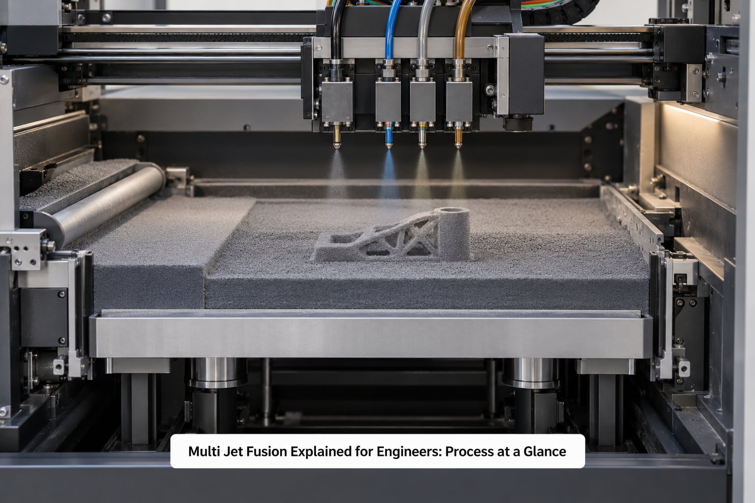
Multi Jet Fusion Explained for Engineers: what each stage controls
The table below maps the eight stages most teams touch, with the parameter your team is really choosing at each one.
| Stage | Input | Outcome | Main engineering control |
|---|---|---|---|
| 1. CAD preparation | Native or meshed CAD model | Watertight print-ready mesh | Wall thickness, minimum feature, orientation |
| 2. File preparation | Print-ready mesh | Sliced layer stack with agent definitions | Surface roughness, hole compensation, texture targets |
| 3. Build preparation | Sliced build file | Loaded build with fresh powder bed | Batch nesting and powder refresh ratio |
| 4. Deposition | Layer in build chamber | Layer of powder carrying agent pattern | Printbar resolution and drop placement accuracy |
| 5. Fusion | Printed layer | Fused layer, part and powder joined | Infrared energy exposure and thermal profile |
| 6. Cooling | Fused layer stack | Layer cooled below transition temperature | Layer time and cooling rate |
| 7. Powder removal | Finished part in powder | Extracted part plus reusable surplus powder | Breakout and depowdering method |
| 8. Inspection | Extracted part | Measured part and material record | Tolerance sampling plan and coupon testing |
Stages one and two are where most of your engineering leverage sits. Everything after that is the supplier’s process, and it is well controlled.
How Does the Multi Jet Fusion Print Cycle Work?
The cycle repeats a small number of operations, thousands of times, and each one is worth understanding because it explains a downstream design rule.
1. A layer of powder is spread
A recoater arm, or in some systems a build plate that moves forward, lays down a fresh layer of powder across the build area. The layer thickness on current platforms is around 0.08 mm, which sets your vertical resolution and the stair-stepping you will see on curved surfaces.
2. Fusing agent is printed where the part is
The printbar travels across the bed and jets fusing agent precisely along the cross-section of your part at this layer. Everything outside that pattern stays loose powder. Drop placement is what makes fine features and small holes viable, because the fusion pattern is drawn rather than scanned.
3. Detailing agent is printed around it
A second agent goes down around the part boundary. It modulates how heat flows at the edge and controls where the part meets the surrounding powder. This is the step that most distinguishes MJF from SLS and it is why MJF edges look cleaner and why small features survive better.
4. Infrared energy fuses the layer
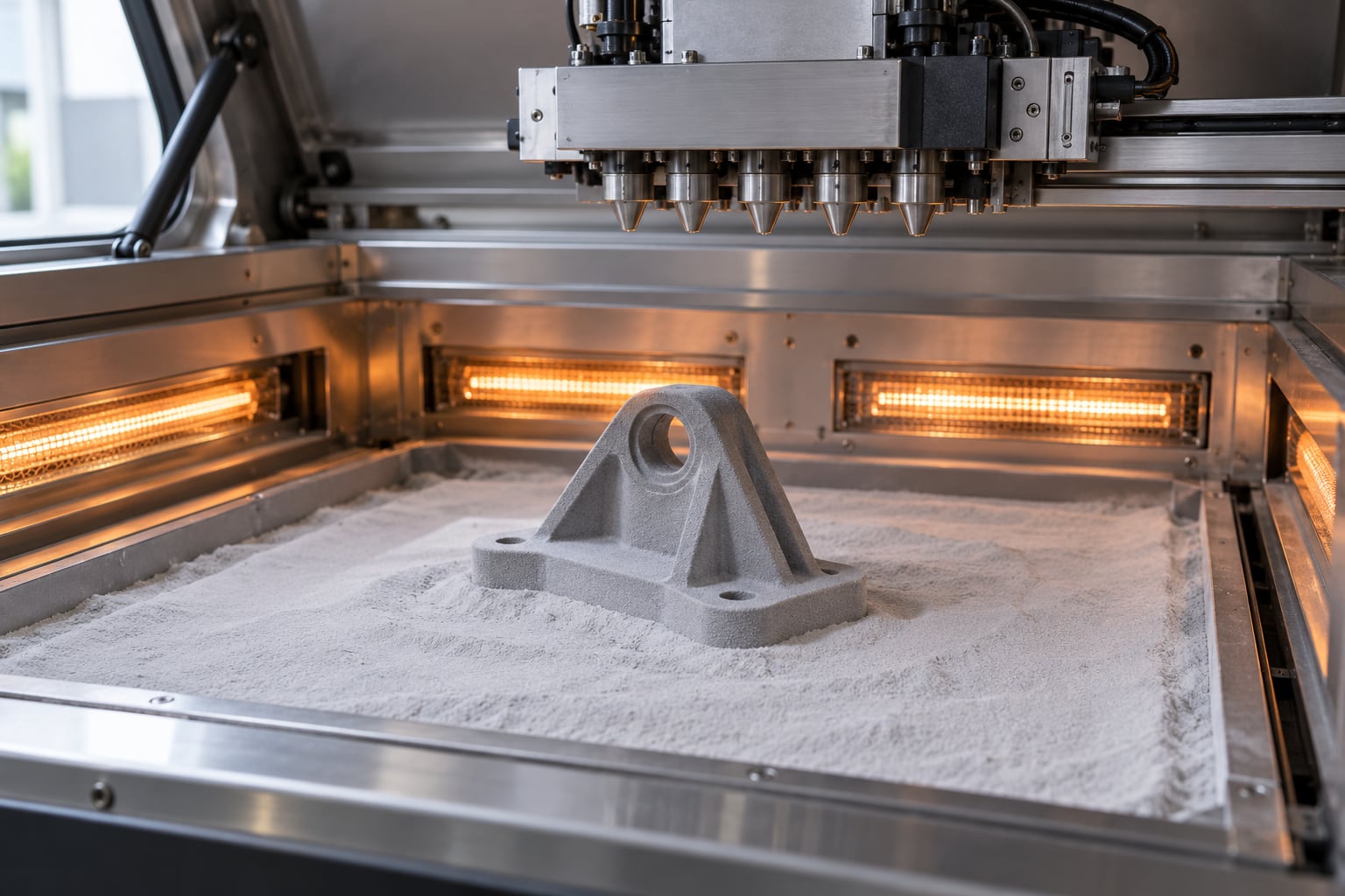
A bank of infrared lamps, with a heating element above and another below in some configurations, raises the whole bed to the polymer’s melting point. The powder under the fusing agent melts and wets into a solid layer. Because the exposure covers the entire bed at once, the time to fuse is set by bed-wide thermal response, not by area scanned.
5. The platform steps down and the cycle repeats
The build platform lowers by one layer thickness, a new layer of powder is spread, and the pattern is printed again. The same agents are used at every layer, which is a large part of why properties are consistent through the build.
Why Multi Jet Fusion needs no support structures
Unfused powder is not an inconvenience here, it is the support structure. Every layer of powder around and under the part holds the geometry while the part cools, and the part stays buried until the build finishes. The thermal argument matters as much as the geometric one: because powder is an excellent insulator, a region surrounded by loose powder cools slowly and evenly.
The practical limits come from heat transfer and bulk density, not from the absence of supports. Because loose powder conducts heat poorly and its bulk density is roughly an order of magnitude below solid plastic, a large thick mass of powder can insulate the area around it so well that heat does not reach it uniformly. That is the root of two common outcomes engineers hit: delamination in very thick sections, and geometry that changes size where it sits in a large mass of powder.
Breakout and depowdering
Once cooled, the part is broken out of the powder bed, then depowdered. Bead blasting with a coarse media is the common next step because MJF leaves powder trapped inside enclosed features, threads and small bores. Budget for that step, and for the geometry that makes it necessary.
What Materials and Mechanical Properties Should Engineers Know?
MJF runs thermoplastic powder. The families you will actually be offered are narrower than a catalogue suggests, and the differences between them matter more than the marketing.
| Material family | What it gives you | What to check before specifying |
|---|---|---|
| PA12 (polyamide 12, nylon 12) | The default. Tough, chemically resistant, stable, easy to process | Datasheet values are usually unfilled and machine-specific; test coupons, not brochure numbers |
| PA11 (polyamide 11) | Lower moisture uptake and better impact than PA12 in many grades | Availability and colour limits at your supplier |
| Glass or carbon fibre reinforced PA12 | Higher stiffness and creep resistance; higher print temperature | Fibre direction in your build orientation; anisotropic reinforcement overrides isotropic base resin |
| TPU | Flexible, resilient, good for grips and wearables | Support-free printing helps here, but fine features and sharp corners still need testing |
| Polypropylene | Low density, good chemical resistance, lower cost per kg | Warping and thermal management are harder; verify on a test part first |
Reinforcement changes the question you are asking
Unfilled PA12 is close to isotropic, so a part is not dramatically weaker because it is oriented one way rather than another. Add glass or carbon fibre and you have reintroduced strong directional dependence. Fibre alignment depends on how powder spreads and how the melt flows, and it does not follow the geometry the way a machine operator might hope.
So the rule is simple: isotropic claims apply to the base resin, and reinforced grades need orientation-specific data and ideally FEA that knows which direction your load runs.
What the isotropy figure actually means
Vendors quote 97 to 98 percent isotropy for MJF PA12. That number comes from comparing test specimens printed in different orientations under a standard tensile method such as ASTM D638. It tells you X and Z properties are within a couple of percent of each other on a rectangular coupon.
It does not tell you anything about properties near a sharp corner, across a thin wall, in a fibre-reinforced grade, or on a part with an unusual geometry. Isotropy is a statement about axis-aligned coupons, not a guarantee about every direction in every feature. If your design depends on it, test your geometry.
Powder reuse
Surplus powder is collected, sieved and mixed with fresh material before reuse. Suppliers commonly quote a refresh ratio around 20 to 30 percent new powder, meaning most of what comes out of the build goes back in. Repeated heating cycles do gradually affect particle size and shape, which is why the refresh exists and why the ratio is not 100 percent.
That reuse is a genuine sustainability argument, and it also has an engineering consequence: parts from an early build in a powder batch are not identical to parts from the last build using that batch. For a qualified end-use programme, ask how powder batches are tracked.
How Should Engineers Prepare Parts for Multi Jet Fusion?
This is where MJF design rules matter most, because most of them come straight from the thermal cycle you just read about.
Orientation is a mechanical decision
With unfilled resin, orientation is usually driven by surface finish and by getting a good thermal profile rather than by strength. For reinforced grades, orient so the dominant load runs with the fibre as far as the supplier’s data allows. Always check whether a critical feature ends up near the bottom of the bed, close to the platform.
Wall thickness
Most suppliers quote an ideal range of roughly 2.5 mm to 12.7 mm for unfilled PA12. Thinner walls work but reduce strength and trap powder. Thicker walls are the problem area, because a large solid mass of plastic shrinks as it cools and pulls away from itself.
Ribs instead of thick walls
A 4 mm rib carries far more stiffness per gram than a 12 mm slab and cools faster, so it warps less. If you need stiffness in a plate, coring it out with a rib pattern is usually the better call than adding material. The same logic applies to gussets at rib-to-wall junctions.
Bosses, overhangs and sink marks
Bosses fuse well because they grow out of existing material. Keep a consistent radius at the boss-to-wall junction and avoid abrupt section changes. For overhangs, a 45 degree chamfer is the safe starting point and a steeper angle needs a trial. Sink marks and slight distortion tend to appear in thicker sections, which is the single most common reason a well-designed MJF part still comes out warped.
Holes, clearances and small features
Minimum feature size is commonly quoted around 0.5 mm, and holes near that limit need compensation because thermal contraction pulls them slightly smaller. Fit-critical holes deserve either a print-and-measure loop or machining afterwards. One service provider reported that MJF resolved failures they had with resin prints around flexible joints, which is a useful signal: printed tolerances are good enough for snap fits and hinges, but they are not guaranteed fits.
Inserts and threads
Metal heat-set inserts need a hole designed with press-fit clearance and enough surrounding material. Printed threads below about 6 mm are usually decoration rather than function. If a fastener matters, use the insert.
Sharp corners and thermal mass
Add a small fillet at internal corners. Sharp internal corners concentrate stress and act as a crack initiator, and the same rounded-geometry advice that helps moulded parts helps here. Also break up any single huge mass of plastic in your design, for the cooling reasons in the previous section.
What Accuracy and Surface Finish Can Engineers Expect?
Typical achievable dimensional tolerance for MJF is around plus or minus 0.3 percent, quoted by some suppliers as plus or minus 0.30 mm, with laser-based SLS commonly quoted tighter at around plus or minus 0.25 mm. Treat both as achievable bands, not guaranteed ones.
Where the variation comes from matters more than the headline number. Build position in the bed, part size, wall thickness, overhang angle and the geometry of the feature itself all shift the result. A figure quoted without those qualifiers is marketing.
Surface finish as printed is matte, with visible layer texture on curved surfaces and a natural grey, salt-and-pepper appearance in unfilled PA12. It is fine for functional parts and does not meet most cosmetic expectations. The finishing chain covers bead blasting to remove powder, dyeing for colour and surface uniformity, primer and paint, and machining on critical datums and fits.
One warning worth carrying: raised text and cosmetic detail below about 0.5 mm can be softened or removed by secondary operations. If an engraved marking matters to the function, oversize it.
How Do Engineers Validate Multi Jet Fusion Quality?
Validation separates visual inspection from evidence of mechanical performance. Those are different things, and conflating them is how a batch of good-looking parts ends up on the bench failing a load test.
Dimensional inspection
Sample critical features on a coordinate measuring machine or with a calibrated micrometer set. Measure across the range of build positions rather than one corner of the bed, because that is where positional effects show up. Use first article inspection on every new material, orientation or design revision.
Witness coupons
Best practice is to print a set of test coupons in the same build as the parts. Coupons carry the same thermal history, and their tensile and impact results are the record that connects your part to a material batch.
Material testing and standards
Tensile testing per ASTM D638 is the usual reference point, with flexural, impact and hardness data filling out the picture. Note the test standard next to every number you record, and note the specimen orientation, because that is where reinforcement and any residual anisotropy show up.
Process qualification and traceability
For end-use parts, qualification means proving the process, not just the part: a defined powder refresh ratio, a defined thermal profile, defined post-processing, and records tying a serial number to its powder batch and build report. If a supplier cannot produce that chain, ask harder questions about repeatability before you order a hundred pieces.
Where Does Multi Jet Fusion Fit in Production?
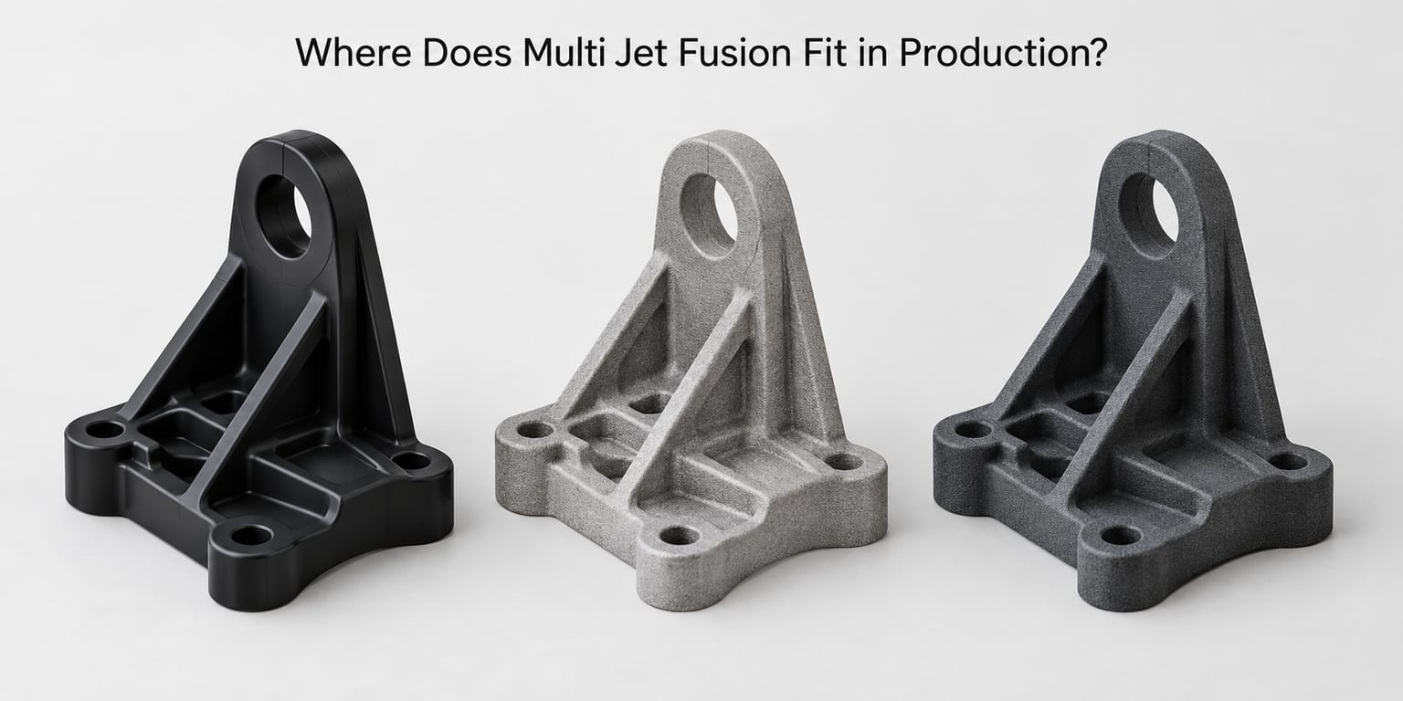
Here is the honest comparison. Volume, geometry and material performance decide it, and no process wins all three columns.
| Criterion | Multi Jet Fusion | SLS | Injection moulding | Binder jetting (MJP) | SLA / FDM |
|---|---|---|---|---|---|
| Economical volume | Prototype to low thousands of parts | Similar band, slower | Thousands and up | Similar band to MJF | One to tens |
| Relative part cost at low volume | Higher per part, no tooling | Lower than MJF, same tooling-free advantage | High, tooling dominates | Mid to high | Lowest at very low volume |
| Internal channels and trapped volumes | Good, support-free | Good, support-free | Limited by tooling | Good | Poor, needs supports |
| Z-axis property consistency | Close to isotropic | Noticeably weaker in Z | Isotropic | Varies with infiltration | Strongly anisotropic in FDM |
| Fine feature and fit accuracy | Good, with detailing agent | Very good at the smallest features | Best, but needs tooling | Limited by binder resolution | Poorest |
| Surface finish as printed | Matte grey, consistent | Similar or slightly rougher | Best | Grainy, needs finishing | Visible layer lines in FDM |
| Material range | Thermoplastic powder, narrow | Thermoplastic and some metal powders | Widest of all | Plastics and sand/metal shells | Resins and filaments, very wide |
| Speed | Faster than laser-based powder bed | Slow, scan-limited | Seconds to minutes per part | Slower, plus furnace step | Slowest in FDM |
A simple decision rule helps. If you need cosmetic surface quality or high volume, moulding wins. If you need one part in a polymer the moulding route cannot reach, or complex internal geometry with no support strategy, MJF is strong. If you need the absolute smallest features at moderate volume, SLS deserves a look.
Practitioners on r/AdditiveManufacturing often report that MJF and SLS produce parts of broadly similar quality and that the visible difference is smaller than expected, with density and finish slightly favouring MJF. For most functional work the process choice is decided by volume, geometry and material rather than by the MJF-versus-SLS debate.
What Are the Main Advantages, Limitations, and Costs?
| Advantages | Limitations |
|---|---|
| No support structures, so complex internal geometry is straightforward | Narrow material range compared with injection moulding or FDM |
| Near-isotropic mechanical properties, including in Z | Natural grey colour and a matte as-printed surface |
| Whole-layer infrared exposure is faster than laser scanning | Small-feature accuracy is slightly behind laser-based SLS |
| Most surplus powder is recycled rather than discarded | Dimensional variation tied to build position and wall thickness |
| Batch nesting lets many parts share one build | Thick sections warp and pick up sink marks above roughly 13 mm |
| Consistent small features thanks to the detailing agent | HP-only technology, so fewer qualified service bureaus |
| Batch production without any tooling cost | Depowdering and finishing are mandatory steps, not optional extras |
The cost reasoning, without the price sheet
Unit economics are driven by four things: machine time, material, post-processing and nesting efficiency. Machine time is fixed per build no matter how many parts are inside it, which is exactly why nesting makes MJF viable in batches rather than singly.
Against SLS you are usually paying a premium per part for faster builds and better Z-direction consistency. Against injection moulding there is no tooling cost at all, so the crossover sits where tooling amortisation plus scrap overtakes the higher per-part machine cost. Nobody publishes that breakpoint cleanly, so model it with your own volumes, labour rates and post-processing steps rather than trusting a vendor calculator.
One rule of thumb that survives scrutiny: include finishing in the comparison. A part that looks cheap raw and needs machining, bead blasting and inspection may cost more finished than a process that prints closer to final.
Frequently Asked Questions
Is Multi Jet Fusion the same as fused deposition modeling?
No. FDM melts extruded thermoplastic filament through a nozzle, layer by layer. MJF is a powder bed process: inkjets print fusing and detailing agents onto polymer powder, then infrared lamps melt the layer. FDM is far cheaper and slower for small parts, and it produces visibly anisotropic parts. MJF prints denser, more consistent parts in batches with no support structures. They are not interchangeable, and FDM is rarely the right choice for a loaded end-use component.
Can Multi Jet Fusion print metal parts?
No. MJF as developed by HP is a thermoplastic powder process. Metals are printed by other powder bed technologies, including laser-based systems that sinter or melt metal powder. That distinction is why you will see MJF grouped with nylon and TPU rather than with aluminium or steel. If your design needs metal, you are choosing a different equipment class entirely, and the design rules, tolerances and finishing options all change with it.
Can unfused powder from a Multi Jet Fusion build be reused?
Yes, most of it, through a controlled refresh rather than straight reuse. Surplus powder is collected, sieved and blended with fresh material before returning to the bed, and suppliers commonly cite a refresh ratio around 20 to 30 percent new powder. Powder that has seen many heat cycles gradually shifts in particle size and shape, which is why the ratio is not 100 percent. For a qualified programme, ask how your supplier tracks powder batches.
Is Multi Jet Fusion more repeatable than other 3D printing methods?
Repeatability comes from the whole-layer thermal process rather than from the machine brand. The same fusing and detailing agents are printed at every layer, so the thermal history is consistent, and there is no support contact or recoater contact to introduce local variation. Service bureaus also tend to be more standardised than the wider 3D printing market. That said, variation still rises with build position, part size and wall thickness, so first article inspection on every new design is still worth doing.
Does the engineer own the part design or the printing process settings?
You own the design decisions that determine printability: orientation, wall thickness, rib patterns, feature sizes, clearances and material choice. The supplier owns the process settings, including the thermal profile, powder refresh ratio, layer parameters and post-processing chain. The overlap is orientation, which you should specify for mechanical reasons and the supplier should review for thermal reasons. Send the design with your load case attached and ask for their orientation recommendation in writing.
Conclusion
If Multi Jet Fusion is on your short list, work through five things in order. Confirm the geometry and volume against the process-selection table above, choose a material whose datasheet values you can verify against coupons from your own supplier, read their design guidance before you commit to wall thickness and orientation, and budget the finishing chain into your part cost.
Then print one representative part with your load case attached before you order a batch. That single step answers the questions no datasheet can, including whether your fit-critical features survive the thermal cycle and whether your thickest section warps in your geometry rather than the supplier’s example part.