Binder jetting is a powder-bed additive manufacturing process where a print head deposits tiny droplets of liquid binder onto a thin layer of powder, gluing powder particles together one layer at a time until a solid part exists inside the machine. No laser, no melt, no support structures. The part then gets unpacked, cured and finished, and the loose powder around it is recycled for the next build. That is the whole idea in a nutshell, and it is why binder jetting has become the go-to route for sand casting patterns, full-colour models and low- to medium-batch metal parts.
If you have only ever watched a fused filament printer move a nozzle around, binder jetting looks alien. The toolpath belongs to an inkjet head, the material behaves like wet sand, and the finished object is a fragile “green” part that needs a furnace or a curing cycle before it can be touched. The rest of this binder jetting process explained guide walks through the whole sequence, the machine hardware, the materials, the trade-offs and the jobs it suits.
Table of Contents
- 1What Is Binder Jetting?
- 2How the Binder Jetting Process Explained in This Article Works
- 3The Core Parts of a Binder Jetting System
- 4Step 1: Prepare the Digital Design
- 5Step 2: Slice the Model for Binder Deposition
- 6Step 3: Spread the Powder and Deposit Binder
- 7Step 4: Repeat Layers and Build the Part
- 8Step 5: Remove Powder, Cure and Finish the Part
- 9What Materials Are Used in Binder Jetting?
- 10Why Choose Binder Jetting?
- 11What Are the Main Limitations?
- 12Binder Jetting vs. Other 3D Printing Methods
- 13Where Is Binder Jetting Used?
- 14How to Choose a Binder Jetting Workflow for Your Project
- 15Frequently Asked Questions
- 16Is binder jetting the same as powder-bed fusion?
- 17What materials can be used with binder jetting?
- 18Does a binder-jetted part need support structures?
- 19How long does binder jetting take?
- 20What post-processing does a binder-jetted part require?
- 21Is binder jetting suitable for production parts?
- 22Conclusion
What Is Binder Jetting?
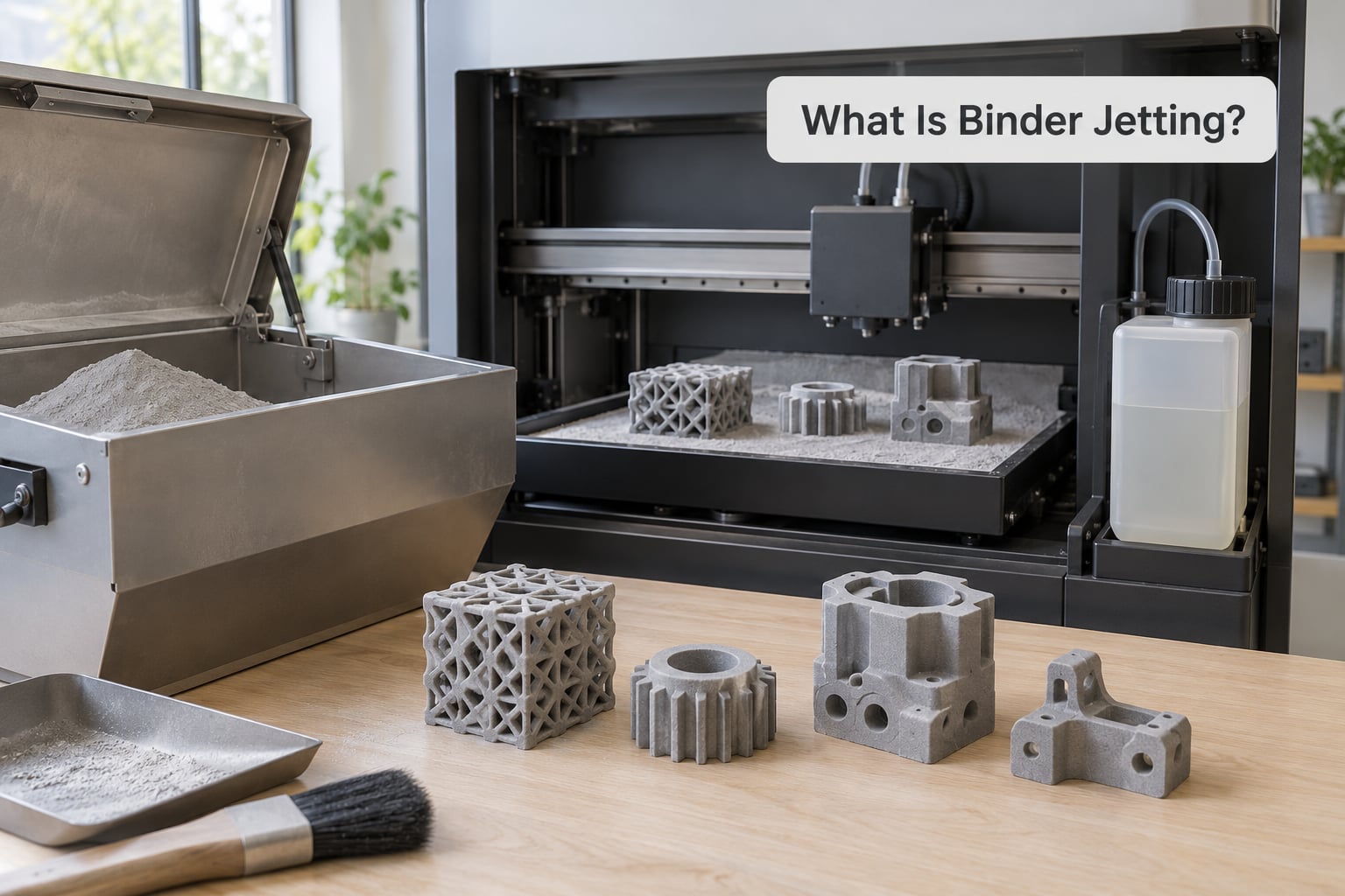
In plain terms, binder jetting joins a granular powder with a liquid adhesive rather than with heat. A slicing program divides the CAD model into cross-sections, a recoating blade drags a thin, even layer of powder across the build platform, and a piezoelectric print head ejects roughly 80 micrometre droplets of binder only where the cross-section says solid material belongs. The wetted powder sets into a fragile shape called the green part, the platform drops by one layer thickness, and the cycle repeats.
Binder jetting is one of the seven categories defined in the ISO/ASTM 52900 standard for additive manufacturing, and it sits alongside material extrusion and vat photopolymerization as one of the seven AM families most readers will ever encounter. It is also sometimes called powder-bed and inkjet, or 3DP, which vendors use freely as a generic name.
The key difference from material extrusion is that the material never moves as a continuous strand. FDM pushes a molten filament through a nozzle, so the deposited material has to be hot enough to flow and cool enough to hold its shape. Binder jetting moves liquid droplets into cold powder, which is why nothing in the build chamber warps, why layer times are short, and why the machine can be physically large without thermal distortion becoming a problem.
How the Binder Jetting Process Explained in This Article Works
Every binder jetting cycle is the same six actions repeated. Here is the sequence in full, from a digital file to a finished component:
- A recoater spreads a fresh, uniform layer of powder across the build platform and pushes the previous layer down by one layer thickness.
- The print head jets droplets of binder over the cross-section defined by the sliced model, and only over that cross-section.
- The binder wets the powder and holds it in place, creating this layer of the green part.
- The build platform lowers, and the powder supply delivers more powder to the spreading area.
- Powder that never received binder stays loose and ready to be spread over the next layer, so there is no wasted material in the build chamber.
- Layers repeat until the part is complete, still buried in powder, at which point depowdering and post-processing begin.
Layer thickness depends on the material. Metal binder jetting commonly runs between 35 and 50 micrometres, full-colour systems around 100 micrometres, and sand systems much coarser at 200 to 400 micrometres because sand grains are large. As one reference machine puts it, a production binder jetting system can deposit two layers a minute while holding layer heights down near 0.09 to 0.20 mm.
The Core Parts of a Binder Jetting System
A binder jetting machine is less exotic than it sounds once you know the six jobs it has to do:
- Recoater and powder supply. A blade or roller spreads powder from a supply chamber across the build platform, returning excess powder to a reserve. On sand systems the grains can be quartz sand, cerabeads or chrome ore, so the spreader has to cope with fairly coarse, abrasive media.
- Binder dispensing system. A piezoelectric inkjet print head holds the liquid binder in a cartridge and ejects droplets on demand, with recirculation keeping the fluid moving between passes.
- Build platform. The piston-driven platform moves down one layer at a time. Because bonding happens at room temperature, platforms can be physically huge without a heated chamber warping them.
- Thermal or curing system. Some systems warm the chamber to help the binder set and to manage polymer materials; others do the curing later in an oven.
- Powder recovery equipment. Depowdering units agitate and blast the unbound powder off the part, filter it, and return it to the supply. In production this recycle loop is where much of the material economics live.
- Software. The build preparation software slices the CAD file, sets layer thickness and binder volume, assigns colours where the machine supports them, and packs many parts into one build in what is called bin packing.
Step 1: Prepare the Digital Design
Preparation starts before the file is opened in the slicing software, because binder jetting is unforgiving about thin features. Parts with walls thinner than the process can hold, sharp internal corners, and delicate unsupported structures tend to fail during printing or depowdering rather than during sintering.
Orientation matters too. Because the sintering furnace shrinks parts significantly, designers scale the model up by the expected shrinkage figure before printing: roughly 20% for sintered metal, and around 0.8 to 2% for bronze-infiltrated parts in the 25 to 75 mm range, closer to 3% for larger infiltrated parts. Service providers recommend agreeing these compensation figures with the machine operator at design stage rather than guessing.
Supports are usually unnecessary. Any part is self-supported inside the powder bed, which is one of the biggest practical differences from FDM or SLS, where overhangs below a certain angle need scaffolding.
Step 2: Slice the Model for Binder Deposition
Slicing converts the solid model into a stack of cross-sections and a set of machine instructions. The operator picks layer thickness and binder volume, and the software generates the pass plan for each layer.
For full-colour machines this is also where colour is decided. Two workflows exist: assigning a colour per face for models with large flat areas, and painting a texture map for smooth gradients, skin tones or geological sections. Engineering packages handle both, so the colour decision stays in CAD rather than in a separate painting tool.
Finally the software arranges parts across the platform. Bin packing determines how many components fit in one build, and it is the single biggest driver of cost per part in production work.
Step 3: Spread the Powder and Deposit Binder
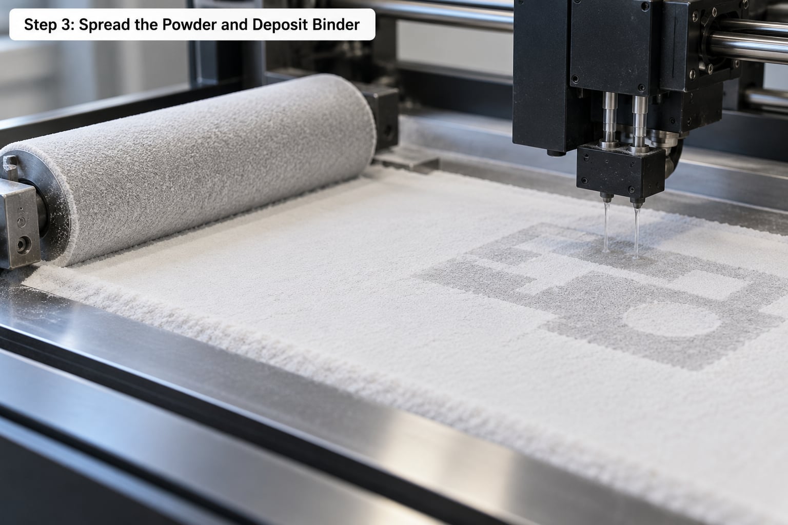
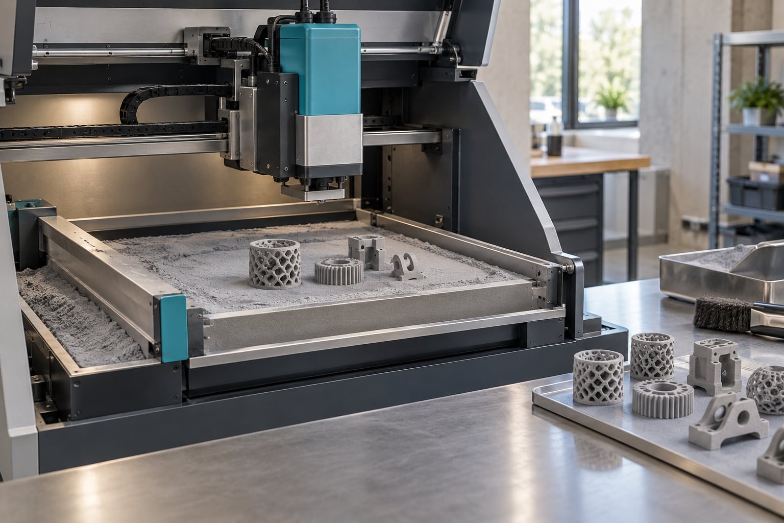
Spreading is fast and mechanical. The recoater blade pushes powder from the supply side across the platform in one smooth pass, shearing off an excess that falls into a collection area. Powder that lands on an already-printed layer just becomes part of the loose bed underneath the next one.
Deposition is selective. The print head sweeps over the platform and ejects droplets only where the cross-section calls for solid material, wetting the powder just enough to bind it. The binder chemistry varies with the powder, and vendors label these families by binder type: furan resin binders (FDB and ODB) for foundry applications, phenolic resin binders (PDB) for polymer and composite parts, and water glass and water-based chemistries (IOB and CDB) where a lower-viscosity liquid is wanted.
After the pass, the binder needs a moment to wet the particles fully. Set too wet and layers slump; set too dry and powder lifts off in the next pass. Getting this balance right is what makes the process repeatable rather than experimental.
Step 4: Repeat Layers and Build the Part
The platform drops by exactly one layer thickness, the recoater returns with fresh powder, and the cycle starts again. Nothing is scanned between layers the way a laser-melted powder bed is, which is part of why layer times stay short.
The part gains shape but almost no strength. It sits in what is called the green state, held together by binder bridges between powder particles, and it is fragile enough that careless handling at this point destroys parts. Everything the process has gained in geometry, it now needs back in post-processing.
Step 5: Remove Powder, Cure and Finish the Part
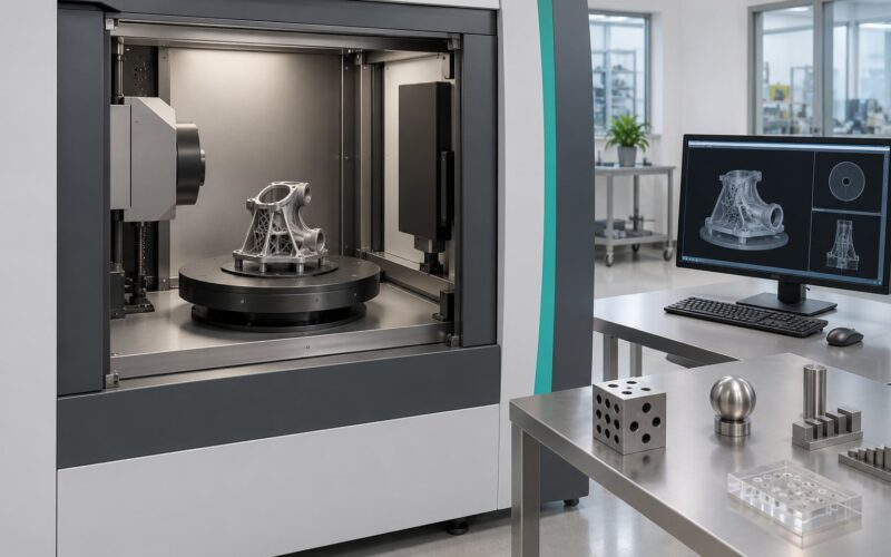
Depowdering comes first. The part is lifted out, and powder is agitated and blasted off it, then filtered and returned to the supply. Parts get inspected here, because defects caught before the furnace are cheap and defects caught after are not.
What happens next depends entirely on the material:
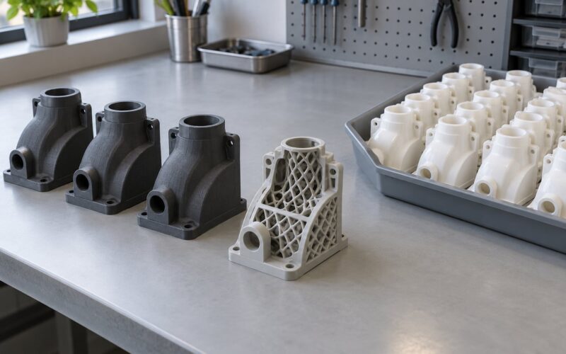
- Gypsum, sandstone and polymer powders. The part is cured or infiltrated with a cyanoacrylate or epoxy, which hardens the loose body into a usable solid. No furnace cycle is needed.
- Metal powders. The binder is removed in a debinding or burn-out step, then the part is sintered to full density or infiltrated with a lower-melting metal, usually bronze, which flows into the porosity by capillary action. Sintered parts reach roughly 97% density; infiltrated parts land near 90%, which matters a great deal in fatigue-critical loading.
Metal parts that need higher mechanical performance sometimes go through hot isostatic pressing after sintering to close internal pores. Sintering also brings furnace-plate friction and non-uniform shrinkage that can warp unsupported areas, another reason designers keep an eye on geometry.
Finally, parts get finished. Bead blasting typically takes binder jetted metal from about Ra 6 micrometres to roughly Ra 3, and CNC machining is common for datums, bores and mating faces. As-built binder jetted metal at Ra 6 is already smoother than DMLS or SLM parts at Ra 12 to 16, but neither is smooth enough to sell as a finished consumer surface.
What Materials Are Used in Binder Jetting?
The powder, not the machine, decides what a binder jetting shop can make. The four families you will see most often:
- Polymers and gypsum composites. PMMA, ABS, nylon and polycarbonate powders, plus gypsum and sandstone blends for full-colour models. Layer thickness around 100 micrometres, cured rather than fired.
- Metals. Stainless steel 316 and 316L, Inconel nickel alloys, and tool steels. Layers of 35 to 50 micrometres, sintering or infiltration required.
- Sand. Silica sand for foundry cores and molds, bonded with furan resin binders at 200 to 400 micrometre layers.
- Ceramics. Alumina, silicon carbide, titanium dioxide and zirconia for cores, shell tooling and refractory parts. Note that reaction-bonded ceramic parts from this route do not reach full density, which limits structural use.
Why Choose Binder Jetting?
No support structures. Every feature is held by surrounding powder, so geometry is limited only by powder grain size and droplet resolution.
Speed. Layer times are short and there is no melt, no scan strategy and no chamber warm-up. High-volume shops treat this as the fastest AM route to functional parts.
No thermal distortion. Bonding at ambient temperature means large build volumes and no warping from heat, which keeps tolerances predictable across big parts.
Low material waste. Unbound powder is recovered and reused, and the recycle ratio in a well-run production cell is very high.
Full colour in one machine. Multicoloured prototypes, topographical models and anatomical models come out of the same build without separate painting or assembly.
Cost for non-critical metal parts. Service providers report metal binder jetting running up to ten times more economically than DMLS or SLM for low-stress components, which is a large part of why foundries and oil and gas users adopted it.
What Are the Main Limitations?
The same features that make binder jetting attractive create its headaches:
- Rough as-built surfaces. Ra 6 micrometres on metal is not a finished appearance. Expect blasting, machining or coating.
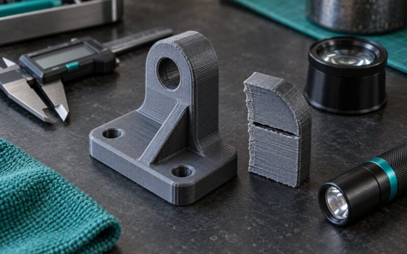
- Brittle green parts. Parts fracture during depowdering and handling, a failure service providers report constantly. Design for handling, not just for the furnace.
- Shrinkage and distortion. Around 20% linear shrinkage in sintering, and non-uniform shrinkage plus furnace-plate friction can warp unsupported regions.
- Porosity that drives fatigue. Infiltrated parts sit near 90% density, and those internal pores become crack initiation sites. For fatigue-critical loading, choose powder bed fusion or add hot isostatic pressing.
- Material choice is narrower than laser processes. High-melting refractory alloys are largely out of reach for the sintering route.
- Equipment cost. These are industrial machines, not desktop toys, and material qualification takes time. Most makers access the process through a service bureau or at an event demo rather than owning a unit.
Binder Jetting vs. Other 3D Printing Methods
| Process | How material is joined | Typical use | Where binder jetting wins or loses |
|---|---|---|---|
| Binder jetting | Liquid binder into powder, then cure, sinter or infiltrate | Sand cores and molds, full-colour models, low-stress metal parts | Wins on speed, price, size and geometry; loses on surface finish and porosity |
| Material extrusion (FDM) | Molten filament laid in beads | Cheap prototypes, functional parts | Binder jetting is far faster and larger; FDM wins on machine price and material availability |
| Vat photopolymerization (SLA/DLP) | Cured liquid resin | Detailed models, dental patterns | Binder jetting wins on size, colour and speed; vat wins on surface detail and accuracy |
| Material jetting | Droplets of liquid material or wax, jetted directly | Patterns, dental models, cast parts | Both jet droplets, but material jetting deposits the part material itself, while binder jetting deposits glue into powder |
| SLS and MJF | Laser or heat sinters polymer powder | End-use polymer parts, lattices | Sintered parts need no infiltration; binder jetting prints colour and supports larger builds |
| Powder bed fusion (DMLS/SLM) | Laser melts metal powder | Fatigue-critical metal components | Binder jetting is cheaper and faster; powder bed fusion gives dense, certified properties |
| Directed energy deposition | Focused energy melts feedstock as it is deposited | Repair, cladding, large metal parts | Binder jetting wins for small complex shapes; DED wins for large parts and coatings |
The distinction worth memorising: material jetting deposits the actual part material drop by drop, while binder jetting deposits glue onto powder that only becomes material after curing or sintering. That one difference explains the speed, the price and the surface finish all at once, and it is the first question to settle when comparing the binder jetting process explained here against any other jetting method.
Where Is Binder Jetting Used?
Foundries and casting. Sand cores and single-use molds are the classic application. The binder jetting process explained here applies directly: a furan-bonded sand core printed overnight can be more complex than a sand-compacted one, and it removes the pattern-making step from the critical path. Engine block castings have been produced this way as multi-part core sets.
Full-colour presentation models. Architecture, topographical and scale models print in one pass with real colour and texture maps, no assembly required.
Low-stress metal parts. Oil and gas stators, housings, manifolds and jigs printed in stainless steel and bronze infiltrated, where cost beats fatigue performance.
Tooling and fixtures. Rapid tooling patterns, injection mould prototypes and shop-floor handling aids.
Medical and anatomical models. Bone-derived geometry printed in biocompatible or visualising materials for planning and communication.
Demonstrations. Because most of these are industrial machines, a growing number of people first see the process live at additive manufacturing expos, where vendors run full-colour and sand demonstrations on the show floor.
How to Choose a Binder Jetting Workflow for Your Project
Ask five questions before committing to a process:
- How big is the part? Binder jetting tolerates large volumes well. Very small parts are often uneconomic because the powder grain size limits feature resolution.
- How complex is the geometry? Internal channels, lattices and undercuts are where this process beats everything else. Simple shapes may be cheaper on another process.
- What quantity? Below a handful of parts, service bureau access beats buying access. Above dozens, the economics of bin packing start to matter.
- What material and finish? Decide early whether a cured polymer model, a sand core or a sintered metal part is the target, because each has a different tolerance and shrinkage model.
- What post-processing will you fund? If no machining, blasting or infiltration budget exists, binder jetting is the wrong choice even when the geometry fits.
One practical habit: send the design to the service bureau before you finalise it. They will tell you what their machine actually holds, what the real shrinkage figure is, and where they have broken parts before.
Frequently Asked Questions
Is binder jetting the same as powder-bed fusion?
No. Both use a powder bed, but they join the powder in completely different ways. Binder jetting wets powder with a liquid adhesive and later cures, sinters or infiltrates it. Powder bed fusion melts powder directly with a laser. That makes fusion parts fully dense and fatigue-capable, while binder jetted parts are faster and cheaper but carry around 10% porosity after infiltration.
What materials can be used with binder jetting?
Four families cover most work. Polymers and gypsum composites such as PMMA, ABS, nylon, PC and sandstone for full-colour models. Metals including 316 and 316L stainless steel, nickel alloys and tool steels. Silica sand with furan resin binders for foundry cores and molds. And ceramics such as alumina, silicon carbide, titanium dioxide and zirconia for cores and refractory tooling.
Does a binder-jetted part need support structures?
No. The part is supported by the surrounding powder bed at every stage, so overhangs, bridges and internal channels are held in place without added scaffolding. This is one of the main reasons engineers pick binder jetting over FDM or SLS for complex geometry. The limit is not supports but feature size: features finer than the powder grain and droplet resolution will not form reliably.
How long does binder jetting take?
A single layer is deposited in a few seconds, and production systems run roughly two layers per minute, so a moderate metal part prints in hours rather than days. Then factor in post-processing: depowdering, debinding and a sintering cycle add hours more, and infiltration adds several days. For small polymer and colour models the whole cycle is often done in a single working day.
What post-processing does a binder-jetted part require?
Every binder jetted part needs depowdering and curing at minimum. Polymer and gypsum parts are infiltrated with cyanoacrylate or epoxy to harden them. Metal parts go through debinding or burn-out, then either sintering to about 97% density or bronze infiltration to roughly 90%. Most metal parts are also bead blasted, and bores or datums are frequently CNC machined.
Is binder jetting suitable for production parts?
Yes, for the right parts. Foundries run sand cores and molds in production, and manufacturers use infiltrated metal for housings, stators and fixtures in low- to medium-batch volumes. It suits production where cost per part matters more than certified fatigue performance. For load-critical, fatigue-driven components, powder bed fusion with hot isostatic pressing remains the safer choice.
Conclusion
Binder jetting is a fast, low-waste way to build parts by gluing powder into shape layer by layer, then curing, sintering or infiltrating it into something you can hold. That is the binder jetting process explained in one sentence. It shines on large, complex, support-free geometry in sand, polymer and lower-stress metals, and it struggles with surface finish, brittle handling and anything fatigue-critical.
Start with the simplest check: does your part fit in a powder bed at the resolution your material allows, and can you budget for post-processing? If both answers are yes, send the design to a service bureau and let them confirm the shrinkage figure before you finalise the CAD. That single conversation saves more broken prototypes than anything else in this guide.