Topology optimization for printed parts is a way of deciding where material actually belongs inside a part. You hand a solver a design space, a set of loads and a few rules about what the part must not do, and it works out the leanest internal shape that still carries the load. Because a 3D printer can build shapes a mill never could, that lean shape gets printed rather than simplified back into a boring bracket.
The catch is that the result is only as good as the inputs. Feed in a sloppy load case and you get a beautiful, lightweight, completely useless part. Most of what follows is about getting those inputs honest before the solver runs.
Table of Contents
- 1What Is Topology Optimization?
- 2How Does Topology Optimization for Printed Parts Work?
- 3What Loads, Constraints, and Objectives Should You Define?
- 4Load cases
- 5Supports and symmetry
- 6Objectives side by side
- 7What Does Topology Optimization Change About Your Design?
- 8How Do You Make an Optimized Part Printable?
- 9Which Topology Optimization Software Options Are Available?
- 10How Do You Choose the Right Objective for a Printed Part?
- 11What Are the Main Limitations and Mistakes?
- 12When Is Topology Optimization Worth Using?
- 13Frequently Asked Questions
- 14Can topology optimization be used with any 3D printer?
- 15Is a topology-optimized model stronger than a uniformly thick part?
- 16What is the difference between topology optimization and generative design?
- 17Does topology optimization make a part automatically safe to print?
- 18How do you choose minimum wall thickness for an optimized model?
- 19Can you topology-optimize an existing CAD model without redesigning it?
- 20Conclusion
What Is Topology Optimization?
Topology optimization is a computational method that distributes material inside a defined design space to meet a stated objective, usually minimum weight or minimum strain energy, while respecting the constraints you set.
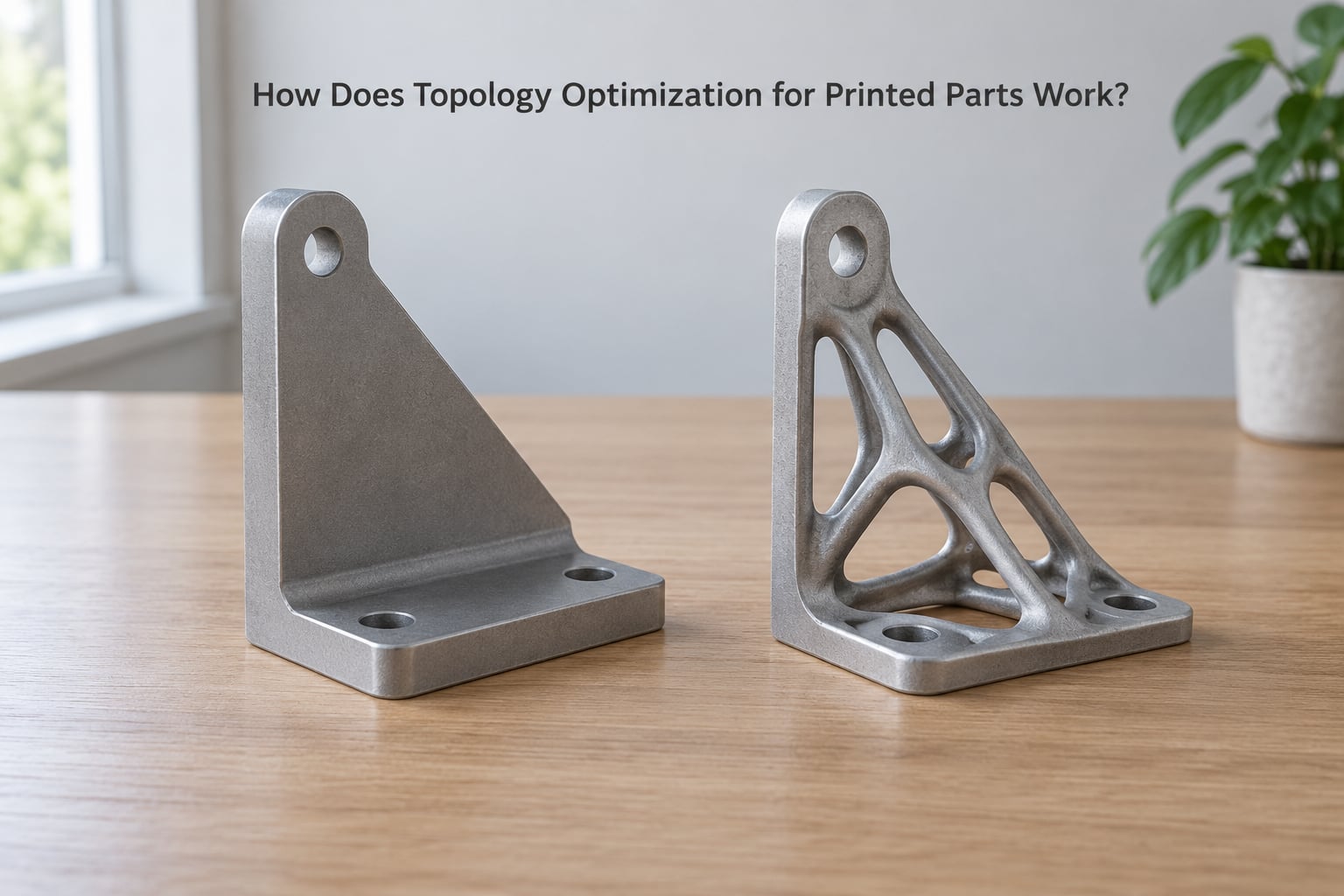
Think of a wall bracket bolted at two points with a weight pulling down in the middle. A conventional design puts material everywhere, because that is how brackets have always been drawn. Topology optimization works out that only the two load paths and the region between them need to exist, and it thins or removes the rest.
Three ideas sit underneath it. Mass reduction means carrying the same load with less material. Stiffness means holding shape under load, which is why stiffness optimisation is the default objective in most engineering work. Material placement is the part people miss: the solver is not shrinking your bracket, it is telling you which regions never needed material in the first place.
The output looks organic. Struts and webs grow along the load paths, junctions thicken where several forces meet, and the interior hollows out. That shape is also the hardest kind of geometry to machine and one of the easiest to print, which is why the two ideas grew together.
How Does Topology Optimization for Printed Parts Work?
The workflow is the same whether you are using a CAD package or a specialist platform, and it goes something like this.
- Build the design space. This is the volume the solver is allowed to fill, usually a simple block that encloses the part envelope. Shrinking the design space tightens the result, because every stray cubic millimetre is an option the solver will use.
- Import the CAD model. The original part usually arrives as a mesh or a solid body. Most tools will not optimise a naked mesh without preparation, so check the geometry is closed and manifold first.
- Define material and manufacturing settings. Printable part technology, minimum wall thickness, maximum overhang angle and whether the process needs supports all change the answer.
- Apply supports. Faces bolted to a frame become fixed constraints. Faces that are free to deflect become displacement or load constraints instead.
- Apply loads. Forces, pressures, moments or acceleration cases, each with a direction and a magnitude. Static loads and load cases are where most mistakes are made.
- Choose the objective and limits. Minimum weight, minimum strain energy, maximum stress, or a displacement limit at a specific point.
- Run the solver. It iterates: analyse, remove low-value material, re-analyse, repeat until the objective and constraints converge.
- Filter and edit the result. Export the mesh, close holes, thicken features that fell below the minimum, add fillets, then rebuild clean CAD geometry around it.
- Validate before printing. Re-run a static analysis on the filtered solid with the real material properties, then print a scaled-down coupon if the part carries real load.
That last step is the one people skip, and it is the one that decides whether the part survives contact with reality.
What Loads, Constraints, and Objectives Should You Define?
Every decision here is a modelling assumption, and the solver can only be as honest as the assumptions you give it. Getting the boundary conditions right matters more than choosing an exotic algorithm.
Load cases
Decide how many distinct loading situations the part actually sees. A camera bracket on a tripod sees wind load and a clamped head, not a static 5 kg block. Model each one separately, because a single combined case hides the path where the structure is weakest.
Supports and symmetry
A bolted face is a fixed support. A bearing seat is not; it rotates and translates within limits, and treating it as fixed produces a part that is stiffer in the model than in the fixture. Symmetry constraints are useful on parts that are genuinely symmetric, and disastrous on parts that only look it.
Objectives side by side
| Objective | What it minimises or maximises | Use it when | Watch out for |
|---|---|---|---|
| Minimum weight | Total material volume | Every gram matters, loads are static and well understood | Feature sizes get tiny; stiffness is only preserved indirectly |
| Minimum strain energy | Compliance of the whole structure | You want maximum stiffness for the least material, the usual engineering default | Can leave disconnected islands and faint members |
| Maximum stress | Peak von Mises stress | Fatigue or brittle materials dominate the failure mode | Stress concentrations at fixed supports can dominate the result |
| Displacement limit | Movement at a named face or point | A locating feature, a sealing face or a heat sink base has a flatness or deflection limit | Tells you nothing about stress unless you add a second limit |
| Frequency or mode shape | Natural frequency or mode shape | Vibration dominates, such as housings near a motor | Load cases no longer describe the part well; mode-based setup is needed |
| Thermal or multi-physics | Heat removal, distortion, fluid flow | Conformal cooling channels and mould inserts | Longer solve times, far more demanding modelling |
Most hobby and shop projects only need the first two. Resist the urge to open every door at once.
What Does Topology Optimization Change About Your Design?
It changes the shape of the answer, not the logic of the design. What comes back is driven by the load paths you defined, so the difference is visible in the model itself.
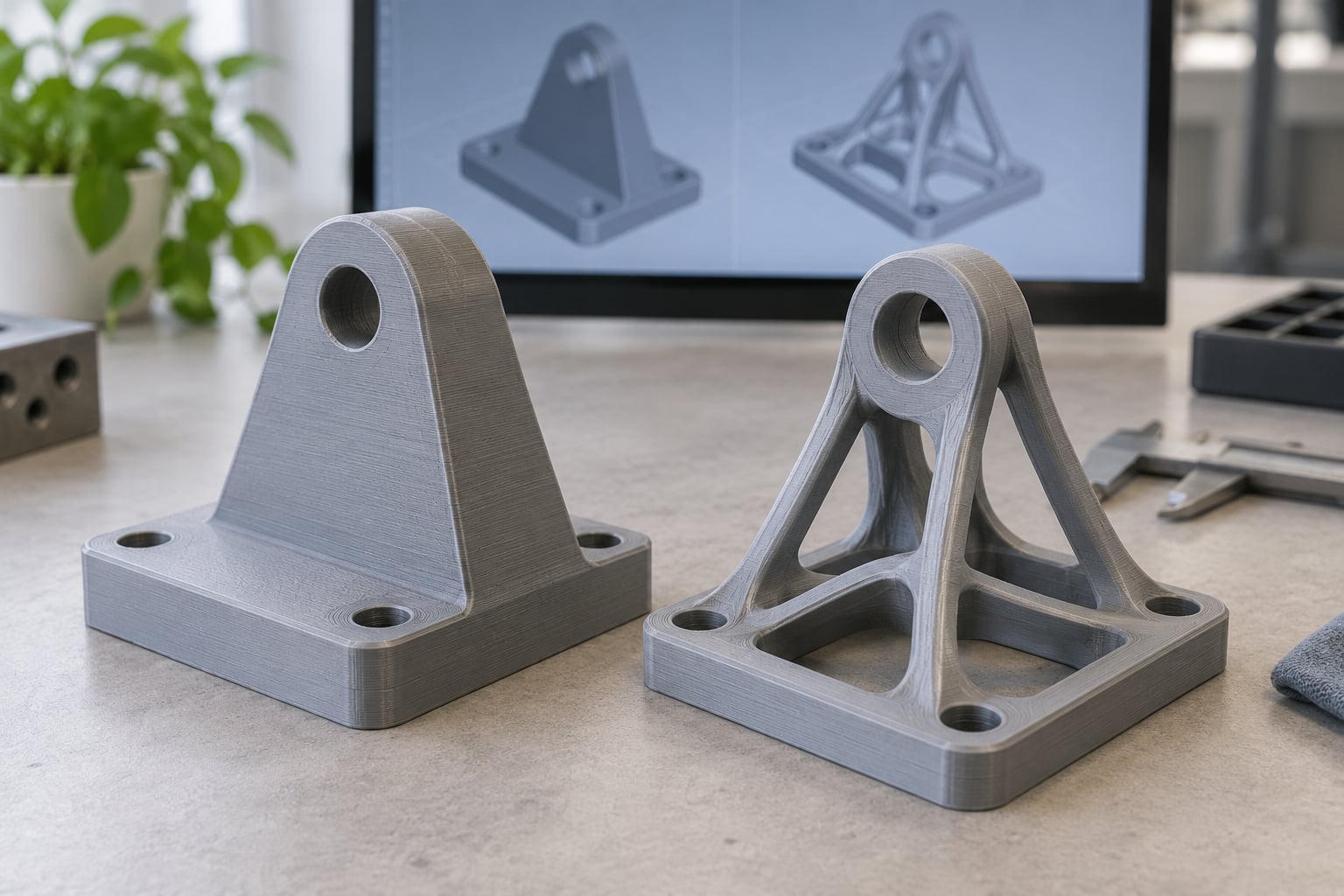
A conventional bracket has flat faces, constant thickness, filleted corners and a shape a machinist could make from stock. An optimised bracket has ribs following the force lines, thick nodes where two ribs meet, and open space where nothing was being used. The silhouette becomes irregular and the interior becomes structure.
Two things follow from that. First, the part has an obvious direction: rotate it and it will not work, so orientation stops being a slicer setting and becomes a design decision. Second, complexity is not the same as performance. A wildly organic result with a badly defined design space will be light and weak.
The honest test is deflection under load compared with the original part, not how impressive the shape looks.
How Do You Make an Optimized Part Printable?
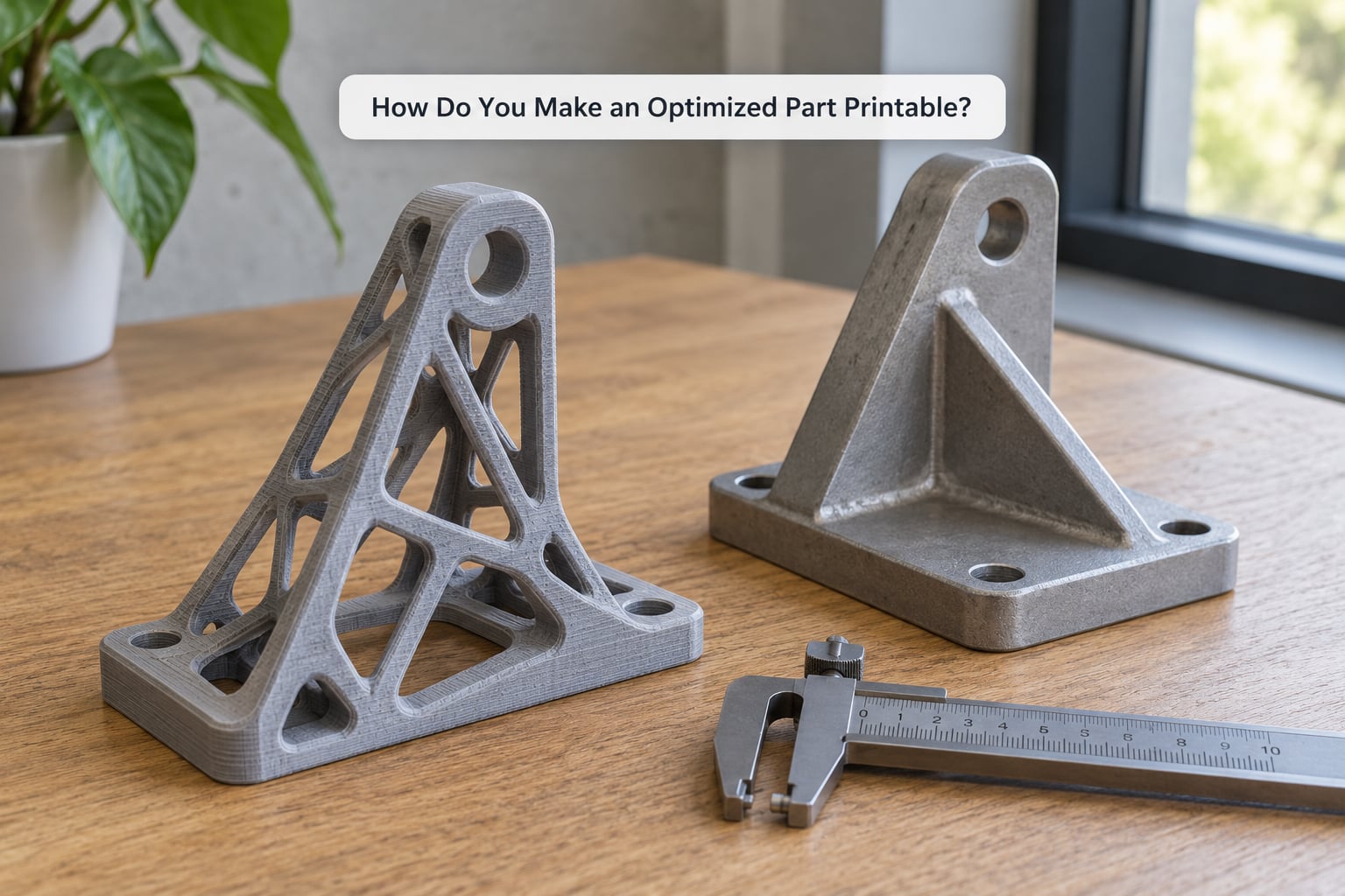
This is where most optimised designs fail, because the solver is not thinking about your nozzle.
Minimum wall thickness is the number that matters most. Most desktop FDM printers can hold a reliable 0.8 to 1.2 mm wall, resin printers manage thinner, and metal powder beds have their own minimum, usually stated as a diameter or a gauge. Set the constraint at or slightly above what your process produces cleanly and the solver will route material accordingly.
Overhang angle decides how much support material you inherit. Around 45 degrees is the classic FDM rule; some specialist tools let you set an overhang shape control that biases the solver toward more self-supporting geometry instead of letting it create horizontal shelves that need a forest of supports underneath.
Trapped powder is the reason to think twice about closed internal voids in powder processes. Hollow sealed cavities cannot be depowdered, and a part that cannot be cleaned internally is a part you cannot inspect internally. Leave escape holes or keep internal channels open.
Feature size and small holes come next. Optimisers happily produce 0.5 mm webs and 1 mm pin holes that clog nozzles, trap powder and snap off the build plate.
Orientation has to be chosen after the fact, based on the load direction the solver produced. Layer adhesion runs perpendicular to the build plate, so the main ribs should ideally be aligned with it.
Surface finish and post-processing close the loop. FDM leaves visible layer lines, resin parts need washing and curing, metal parts need support removal, machining of bearing seats and thread inserts, and often heat treatment. Budget time for it, because support removal on a webbed part is genuinely tedious.
Which Topology Optimization Software Options Are Available?
Options fall into three groups, and the honest difference between them is how much of the workflow they handle for you.
| Option | Type | Strong at | Learning curve | Best for |
|---|---|---|---|---|
| Autodesk Fusion 360 generative and topology tools | Built into a general CAD package | Accessible start, familiar modelling environment | Low to moderate | First projects, parts you also need to edit conventionally afterwards |
| SOLIDWORKS simulation and topology studies | Built into a general CAD package | Keeping the part in one assembly environment | Moderate | Shops already running SOLIDWORKS for the rest of the design |
| FreeCAD with an external solver | Free and open source | Cost, full control, community add-ons | Steep, because pieces live in several places | Budgets where licence cost is the blocker |
| Altair Inspire and OptiStruct | Specialist optimisation suite | Overhang and self-supporting shape controls, robust solvers | Steep | Printed parts where support avoidance drives the design |
| nTopology | Specialist platform | Automated conversion of results into editable geometry, lattices | Steep | Saving manual reconstruction time on complex results |
| Ansys and ParaMatters | Simulation suites with optimisation | Multi-physics, thermal and fluid-driven design | Steep | Cooling channels, mould inserts, coupled analysis |
Reviews of the built-in tools describe them as accessible but limited once you need control over the result. Specialist platforms win on automation and overhang handling. Free and open-source routes work, and hobbyists do report success with simple parts, but the documentation is thin and the workflow is spread across several tools, so budget more time there.
How Do You Choose the Right Objective for a Printed Part?
Start from how the part fails, not from which objective sounds most impressive.
If it snaps, the material’s strength or fatigue limit is the constraint, so run a stress-based objective with a limit set well below yield and check the result with a fatigue-aware analysis. If it bends out of position, use a displacement limit on the face that has to stay put, usually combined with minimum strain energy. If it shakes or resonates, work from mode shapes and target frequencies rather than static loads. If you are chasing filament, powder or print time, minimum weight is honest enough, because material use drives cost directly.
Printed parts have a wrinkle. Layer adhesion means strength differs by direction, so a printed part rarely fails the way the isotropic model predicts. Where failure is the design driver, run the validation analysis with the printed material’s directional properties, or accept a healthy margin.
What Are the Main Limitations and Mistakes?
Wrong loads. The most common failure. Ask where the load comes from, in which direction, and how often it cycles. Guessing produces a light part that fails in an afternoon.
Bad support conditions. Everything bolted down that actually flexes flattens the model, so the part looks stronger in simulation than in the fixture.
Over-smoothed boundaries. Results often have blobby transitions and islands joined by one-pixel webs. Raise the minimum thickness, run more solver iterations, and thin the result back manually where needed.
Non-printable features. Undersized holes, thin webs and sealed voids survive the solver and die at the slicer or on the build plate.
Unjustified organic forms. A result with no load behind it is decoration. If the shape cannot be traced back to a load path, question the setup.
Skipping validation. Re-analyse the filtered solid, not just the raw solver output. Printed parts are anisotropic, slightly porous, and their interfaces are weaker than the base material.
Ignoring support removal. Support structures that reach into a webbed part make the difference between a five-minute cleanup and a long evening with pliers.
When Is Topology Optimization Worth Using?
It pays off where weight is expensive or where conventional geometry is genuinely awkward: drone and satellite frames, robotics links, heat-sink supports and housings, injection mould inserts with conformal cooling, and aerospace brackets where every gram is argued over.
It is also worth it when you need to consolidate several parts into one printed body and no standard fastener or hinge will do the job.
Skip it when the part is small, cheap, statically loaded and already simple. A hand-drawn L-bracket with two holes will beat an optimised version on cost, time and predictability. Optimisation adds modelling setup, solver time and post-processing; that overhead only pays back when the part is doing something interesting under load.
Frequently Asked Questions
Can topology optimization be used with any 3D printer?
Yes, with constraints. Every additive process can build the organic shapes topology optimization produces, but the usable thickness and overhang limits differ. Desktop FDM typically needs walls around 0.8 to 1.2 mm and overhangs near 45 degrees, resin handles thinner walls and sharper detail, and powder bed processes need thicker features plus closed escape routes. Set the manufacturing constraints in the solver to match your machine before you run it.
Is a topology-optimized model stronger than a uniformly thick part?
Not automatically. Strength depends on the material properties you entered, and printed parts are anisotropic with weaker layer interfaces than the base resin or filament. A well-set minimum strain energy objective with sensible load cases gives a part that is stiffer for its weight than a uniform block. A badly set one can produce something light and flimsy, so validate the filtered result with an analysis using printed material properties.
What is the difference between topology optimization and generative design?
Topology optimization is one method: redistribute material inside a design space to meet a single objective and its constraints. Generative design is the broader approach, which may use topology optimization plus multiple materials, multiple load cases, lattices, varying thickness and automated design-space generation to explore many concepts at once. Topology optimization is a technique inside generative design, not the same thing as it.
Does topology optimization make a part automatically safe to print?
No. The solver optimises for structural performance and knows nothing about nozzle size, bed adhesion, trapped powder or support removal. You still have to check minimum wall thickness, overhang angles, feature size and orientation yourself, then slice and inspect. A result full of thin webs and sealed internal voids will slice fine and still fail on the build plate.
How do you choose minimum wall thickness for an optimized model?
Match what your process produces cleanly, not what the machine nominally claims. Print a short wall test at several thicknesses and use the thinnest one that extrudes or cures without gaps. Most desktop FDM parts hold 0.8 to 1.2 mm walls reliably. Enter that value as a manufacturing constraint so the solver keeps every member above it, which usually adds a little material and saves you a reprint.
Can you topology-optimize an existing CAD model without redesigning it?
Yes, and it is the common route. Import the model, wrap it in a simple box to form the design space, fix the faces that bolt to something, apply your loads, and run the solver. You do not redesign anything up front, but you will rebuild clean geometry after the run because the output is usually a mesh. Budget time for that cleanup step before you promise anyone a date.
Conclusion
Topology optimization for printed parts works because a printer can make the shapes it produces. The process is simple on paper: define the design space, fix the supports, apply the real loads, pick one objective, run the solver, then clean up and validate the result.
Start where the plan says to start. Write down the actual load cases, the real support conditions and the minimum wall thickness your machine can hold before you open any solver, and your first run will be worth far more than the fifth one on an untested setup.