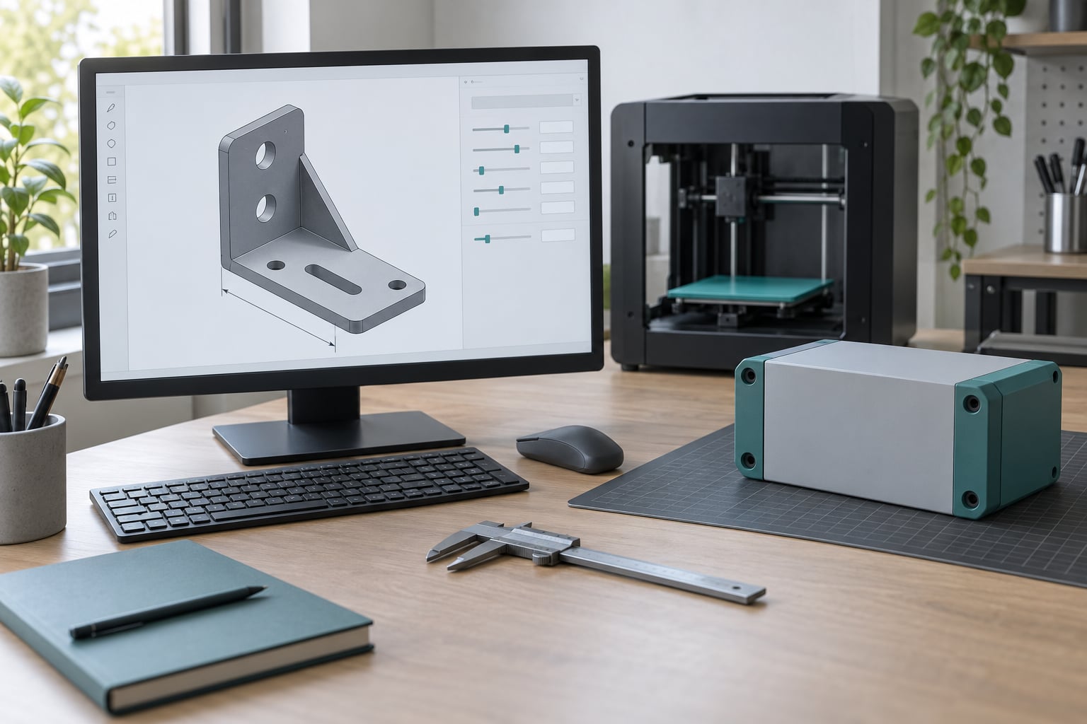
A parametric model is a 3D model built from named variables — width, depth, height, thickness, hole diameter — so that changing a value regenerates the geometry instead of forcing you to redraw it. Learning how to make parametric models for customization takes about a weekend: you define your parameters, drive every feature from them, then publish a model other people can resize and personalize without touching your source file.
That last part is where most makers get stuck. Plenty of people can model a bracket, but far fewer finish the job by giving it parameters and testing the ranges. The workflow below walks the whole path, from a blank file to a printed variant.
Table of Contents
- 1What You Need
- 2Choosing between OpenSCAD, FreeCAD, Fusion 360 and build123d
- 3Step-by-Step
- 4How to define the parameters for your custom model
- 5How to build the base geometry with constraints
- 6How to add features that respond to parameter changes
- 7How to test and validate customization ranges
- 8How to prepare the customized model for 3D printing
- 9Common Mistakes
- 10Quality and version control tips
- 11Frequently Asked Questions
- 12What is the easiest CAD software for learning parametric modeling?
- 13How do I make text or a name change automatically in a parametric model?
- 14Can I use a spreadsheet to control CAD model parameters?
- 15How do I know which parameter values are safe to customize?
- 16Should parametric CAD models be exported as STEP or 3MF for 3D printing?
- 17When is a CAD script better than using parameters in the software?
- 18Start With One Model and Three Values
What You Need
You need four things before you start, and only one of them is software.
- CAD software with parameters. Free options cover this well. OpenSCAD models from a text file, FreeCAD is a full parametric CAD kernel, SolveSpace is a lightweight sketch-based option, and build123d is Python-based for people comfortable with code.
- Basic modeling skill. Enough to make a solid, cut a hole from it, and export it. You do not need to be an engineer.
- Reference dimensions. Real measurements of what you are making — the rod diameter, the phone width, the laptop height. Guessed numbers produce parts that do not fit.
- A slicer and printer, or at least a slicer. You need somewhere to check clearances and overhangs before you promise anyone the model works.
A few things are optional but worth knowing about. Sketch constraints are how GUI-based CAD turns dimensions into driven values. A spreadsheet can drive parameters in FreeCAD or Fusion 360 if you want a single source of truth for a whole product family. Scripts matter once you are generating dozens of variants. None of that is required for your first model.
Choosing between OpenSCAD, FreeCAD, Fusion 360 and build123d
For most makers starting out, OpenSCAD is the fastest route because the model is a file you can read, diff, and commit. Beginners on forums consistently describe it as the friendliest first step, though the draw-style GUI can surprise people used to Fusion or SolidWorks.
| Tool | License | Learning curve | Output | Best for |
|---|---|---|---|---|
| OpenSCAD | Open source (GPL) | Low if you can code, odd if you cannot | Mesh: STL, 3MF, OFF | Customizer-based models, code-first makers |
| FreeCAD | Open source | Medium | STEP, STL, 3MF | Full parametric CAD with sketches and a feature tree |
| Fusion 360 | Free for personal use, commercial licence required | Medium | STEP, STL, 3MF | Professional work and assemblies |
| build123d / CadQuery | Open source (Python) | High | STEP, STL, 3MF | Scripted families and batch generation |
| SolveSpace | Open source | Medium | STEP, STL | Constraint-driven sketches in a small footprint |
One honest limit: OpenSCAD produces a mesh, so it cannot export STEP. That matters if you plan to machine a part or hand the file to someone who needs solids. Printers do not care — mesh is exactly what a slicer wants.
Step-by-Step
Here is the workflow that gets you from an idea to a family of printable parts. I will walk through a name tag with live text, since personalization makes the payoff obvious, but the same steps apply to enclosures, adapters and frames.
How to define the parameters for your custom model
Start by writing down every dimension that a user might reasonably want to change. For a name tag that is the text itself, the tag width, the height, the corner radius, the border width, the hole diameter and the keyring hole size. Then write down the ranges you are willing to support.
Name them in plain language with units attached — tag_width = 60; // mm — and put every parameter in one block at the top of the file. Vague names like a or size2 are what turn a model into an unmaintainable mystery six months later.
The rule nobody writes down: expose inputs, derive everything else. If the hole sits 6 mm from the edge and the border is 2 mm, compute that offset from border instead of adding a sixth parameter. Every extra parameter is another way for a user to produce something that does not print. Usually five to eight inputs is plenty for a published model.
| Parameter | Default | Units | Min | Max |
|---|---|---|---|---|
| tag_text | HELLO | text | 1 character | 18 characters |
| tag_width | 60 | mm | 30 | 120 |
| tag_height | 22 | mm | 14 | 60 |
| corner_radius | 5 | mm | 0 | 10 |
| border | 2 | mm | 1.2 | 4 |
| hole_dia | 4 | mm | 3 | 8 |
How to build the base geometry with constraints
Build the simplest solid that captures the design, then constrain it. In a sketch-based tool you draw a rectangle, fix it to the origin, add horizontal and vertical constraints, and set the width and height dimensions equal to tag_width and tag_height. No number gets typed twice.
In OpenSCAD the same idea looks different but works the same way. You write a module that takes arguments with defaults, then call it:
module tag_plate(w, h, r) {
    hull() {
        for (x = [r, w - r], y = [r, h - r])
            translate([x, y, 0]) cylinder(h = 3, r = r, $fn = 48);
    }
}

tag_plate(tag_width, tag_height, corner_radius);
Sketch solvers also let you lock a relation directly: make the border thickness equal to twice the corner radius, and you have removed a whole class of broken variations before it starts.
How to add features that respond to parameter changes
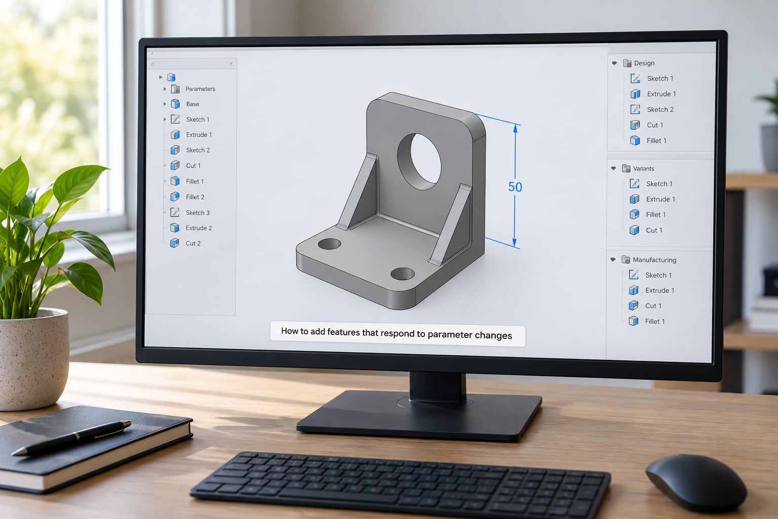
Features that scale are the difference between a model and a template. Holes should track the hole diameter parameter. A hole count should be driven by an integer parameter. Fillet radii should reference the border thickness rather than a number of their own.
Live text is where personalization happens, and it is the feature people search hardest for. In OpenSCAD, text() stays editable, so you pass the string as a parameter and the geometry rebuilds around it:
module name_tag(label) {
    difference() {
        tag_plate(tag_width, tag_height, corner_radius);
        translate([tag_width / 2, tag_height / 2, -1])
            linear_extrude(height = 5)
                text(label, size = tag_height * 0.5,
                     font = "Liberation Sans:style=Bold",
                     halign = "center", valign = "center");
    }
}

name_tag(tag_text);
Two details decide whether this survives contact with real users. The plate is 3 mm tall while the text cut is 5 mm, so the cut passes cleanly through both faces. And the text is centred on the tag rather than at the origin, so long names grow outward instead of drifting off the edge.
In a sketch-based tool the equivalent is a pattern feature with an instance count tied to a parameter, and a text object driven by a string property. A solid-work user moving to FreeCAD reports the opposite result — sketching works fine, but driving everything from a script breaks the body. That gap between interactive sketching and mass parametrization is worth knowing about before you commit.
How to test and validate customization ranges
A model that only works at its default values is not customizable. Test three settings for every parameter: the minimum, the default, and the maximum. Render each one and look at the result rather than trusting that it built without an error.
Check four things on each variation:
- Wall thickness. Anything below roughly 1.2 mm prints badly on a typical FDM machine. Clamp thin walls with
max(border, 1.2)rather than trusting the user. - Hole diameter. A 3 mm hole shrinks measurably during printing. Print-test a calibration part before promising a keyring hole.
- Clearance. Snap fits and press fits need real tolerances measured on printed parts, not on the CAD screen.
- Overhangs. Tall, thin, text-heavy features at ninety degrees will need supports. Angling text five degrees often removes the problem.
Once the ranges hold up, batch generation becomes easy. OpenSCAD renders from the command line, so you can loop over a list of names or sizes and export one file per variant without touching the GUI:
openscad -o tag_ALICE.stl -D 'tag_text="ALICE"' name_tag.scad
openscad -o tag_BOB.stl   -D 'tag_text="BOB"'   name_tag.scad
That single command is why coders like OpenSCAD for customization work.
How to prepare the customized model for 3D printing
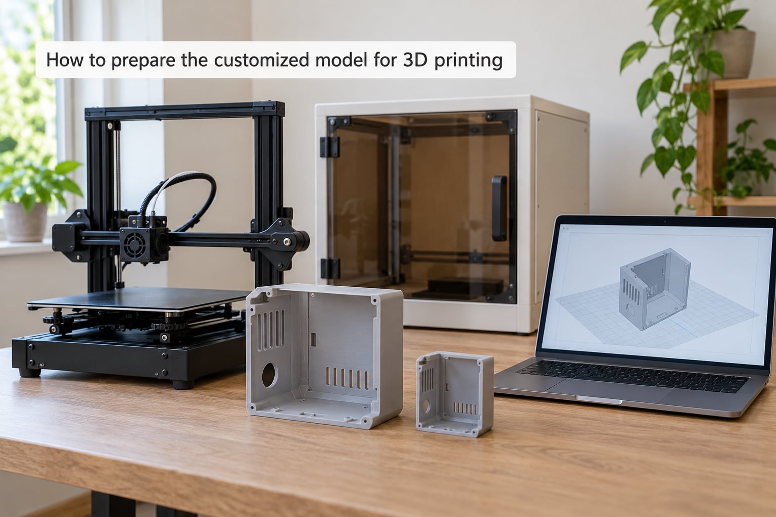
Export the file that matches your purpose. A short comparison covers most cases:
| Format | Editable? | Keeps history? | Colors and parts | Use it for |
|---|---|---|---|---|
| Source (.scad, .FCStd) | Yes, fully | Yes | Whatever you build | Master copy and future changes |
| STEP | Yes, as geometry | No | Solid bodies | Sharing with machinists or CAD tools |
| 3MF | No | No | Yes, per-object color | Multicolor prints and slicer hand-off |
| STL | No | No | No | Universal, dated fallback |
An STL can never be made parametric. It is a triangle soup with no feature history and no variables, so every change means manual editing. That is the source of a lot of frustration in the forums — beginners download a mesh and then wonder why their CAD program cannot move a dimension.
Before slicing, confirm the model exports in millimetres, then open it and measure. A model authored in inches and exported at the wrong scale is the most common silent failure, and it looks like a print that ran out of filament. Load it into your slicer, check the bounding box against the dimensions you expect, look at supports and orientation, and slice the default variation plus one extreme value.
If you are publishing the model rather than just using it, export your source file with parameters and test the customizer interface yourself. Enter an absurd value and confirm the model either clamps gracefully or fails clearly.
Common Mistakes
Over-constrained sketches. A fully constrained sketch has zero degrees of freedom left, so adding a dimension makes the solver complain and the change fails. Leave one degree of freedom on anything you want to resize, and drive it from a parameter instead of fixing it.
Tangled dependencies. When every feature references every other feature, changing one dimension invalidates the whole history and the file becomes unusable. Build in a simple order — base solid, then cuts, then patterns — and keep each feature dependent only on what came before it.
Non-manifold geometry. Two solids touching face to face, zero-thickness walls, and self-intersecting fillets all produce a mesh that slices badly or not at all. Union your parts instead of leaving them coincident, and inspect the solid with your CAD tool’s validity check.
Invalid minimum and maximum values. A fillet radius larger than half the wall thickness, or a hole diameter wider than a narrow band, breaks the model at the extremes. Clamp derived values in the source rather than documenting a rule and hoping users read it.
Poor naming. w2 and temp tell the next person nothing. Use descriptive names with units, and keep the parameter block at the top where a reader expects it.
Scaling errors. Always check the exported bounding box against a known dimension before slicing. Set units explicitly at export rather than trusting the application’s default.
Skipping design checks. Test minimum, default and maximum values before you publish. It takes ten minutes and it catches nearly every complaint a user would otherwise file.
Quality and version control tips
Commit your source file to version control even if you never program. Every parameter tweak becomes a reversible change instead of a lost afternoon. If your model grows past a few hundred lines, split shared geometry into a library module so you are not copying the same rounded-rectangle code into every file.
Keep a changelog of your known-good parameter ranges. When a user reports a failure, you will know immediately whether they fell outside the range you tested.
One licensing note worth knowing: OpenSCAD is GPL-licensed, which shapes where its models can be embedded and how you distribute derived work. Closed-source parametric publishing is a separate conversation that platforms handle differently, so check the license before you build a business on a model you plan to lock down.
Frequently Asked Questions
What is the easiest CAD software for learning parametric modeling?
OpenSCAD is the easiest for most beginners because the model is a plain text file: you read it, edit a number, and see the result. There is no constraint solver to fight and no feature tree to break. FreeCAD is the step up if you want sketch-based modeling, while Fusion 360 suits people already working in commercial CAD. SolveSpace is small and quick but does less.
How do I make text or a name change automatically in a parametric model?
Keep the string as a text parameter rather than converting it to geometry. In OpenSCAD, pass the label into the text function so it regenerates on every change. In Fusion 360 or FreeCAD, store it in a property and reference it from the text tool, then place it on its own sketch layer so you can rotate it to reduce support material.
Can I use a spreadsheet to control CAD model parameters?
Yes, in FreeCAD and Fusion 360 a spreadsheet can hold the values and named cells can drive dimensions directly. The benefit is one place to edit a whole product family. The catch is that you now have two files to keep in sync with the model, so version them together. OpenSCAD does not need this; parameters live in the source file itself.
How do I know which parameter values are safe to customize?
Set a minimum and maximum for every input, then render all three points and inspect the results. Check wall thickness against your printer, hole diameters against measured shrinkage, and clearances against a test print. Clamp risky derived values in the source, such as limiting a fillet to half the wall thickness, so the model degrades gracefully instead of failing.
Should parametric CAD models be exported as STEP or 3MF for 3D printing?
For printing, use 3MF: it keeps separate objects and their colors, which matters for multicolor work, and slicers read it reliably. STEP is the right choice when someone needs solid geometry for machining or another CAD tool. Keep your source file as the master, since neither STEP nor STL can be edited back into a parametric model.
When is a CAD script better than using parameters in the software?
Scripts win once you are generating many variants rather than one. Looping over a list of names or sizes from the command line turns 40 personalized prints into one command instead of 40 manual edits. Interactive parameters stay better when you are still finding the design, because you want to see and change each decision as you make it.
Start With One Model and Three Values
If you only do one thing from this guide, take a model you already know prints and rebuild it as a template. List its dimensions as named parameters, drive every feature from them, then render the minimum, default and maximum values before you do anything else. That is how to make parametric models for customization properly — not by adding parameters, but by proving the whole family builds before you share the first variant.