How to reduce print time and material cost comes down to three levers, and you work them in this order: change the model geometry, then the slicer settings, then the machine setup. Geometry changes cut both time and material at once, which is why reorienting a part usually saves more than lowering infill does. This guide is for FDM printing with filament and a slicer such as Cura, PrusaSlicer, OrcaSlicer or Bambu Studio, not commercial 2D print shops.
Most people attack this in the wrong place. They open the slicer, drop infill to 15%, and wonder why a twenty-hour job only got two hours shorter. The walls, top and bottom layers and perimeters were doing the work all along.
Below is the order I actually work in, followed by a table of what each change typically saves. The whole routine takes an afternoon to set up and pays back on the first print.
Table of Contents
- 1What You Need Before You Reduce Print Time and Material Cost
- 2Step-by-Step: Cutting Print Time and Filament in a Sensible Order
- 31. Measure Your Current Print
- 42. Optimize the Model in Your Slicer
- 53. Use Fewer Shells and the Right Infill
- 64. Reduce Support Material Safely
- 75. Improve Motion and Slicing Efficiency
- 86. Tune Temperatures Without Increasing Warping
- 97. Test One Change at a Time
- 108. Save Confirmed Settings as Profiles
- 11Common Mistakes
- 12Frequently Asked Questions
- 13What setting reduces 3D print time the most?
- 14How can I reduce filament use without weakening the print?
- 15Is lower infill always better for reducing material cost?
- 16Should I increase print speed to save time?
- 17How do I know whether a part is strong enough after reducing walls or infill?
- 18Can support removal reduce material cost without hurting quality?
- 19Conclusion
What You Need Before You Reduce Print Time and Material Cost
You need four things, and only the first one is a machine.
- A baseline measurement. The estimated time and filament grams from your current slicer profile, plus the real numbers from your printer’s own log if you have one.
- Your slicer. Know which one you use and which version, because the setting names change between Cura, PrusaSlicer, OrcaSlicer and Bambu Studio.
- The model and its purpose. Is it a cosmetic display piece, a jig, or something that has to carry load? You cannot judge a trade-off without knowing which.
- A small test object. A simple bracket or calibration shape that prints in well under an hour, so you can test changes without gambling a twelve-hour job.
Write the baseline down somewhere you will see it. Every comparison afterwards depends on it.
Step-by-Step: Cutting Print Time and Filament in a Sensible Order
Work top to bottom. Each step changes one category of thing, so you can tell which adjustment produced which saving. Stop and print when a step stops paying for itself in your specific model.
| Change | Typical time saved | Typical material saved | What you give up |
|---|---|---|---|
| Reorient the model | 10-40% | 5-30% | Surface finish on the largest face |
| Hollow a solid model with drainage holes | 30-70% | 50-80% | Nothing if you keep two walls |
| Raise layer height toward nozzle size | 20-50% | Near zero | Fine detail and surface smoothness |
| Drop from three walls to two | 10-20% | 10-20% | Rigidity on very thin features |
| Cut infill density | 0-15% | 5-25% | Stiffness in the core |
| Switch to a faster infill pattern | 5-20% | Varies | Tensile strength in one direction |
| Switch grid supports to tree supports | 5-20% | 20-60% of support material | A little more surface scarring |
| Fix over-extrusion | 0-5% | 5-15% | Nothing, it is a defect fix |
| Dry filament and fix stringing | 0% | Removes failed-print waste | Nothing |
1. Measure Your Current Print
Open the sliced preview and record five numbers: estimated print time, estimated filament length or grams, layer count, top and bottom layer count, and infill density. Add the support material estimate if the slicer offers one.
Then compare the estimate against reality. Community users on the Ultimaker forum have raised this repeatedly: sliced time and sliced grams routinely disagree with what OctoPrint or PrusaLink actually logs. A printer that pauses to cool, or a machine printing slowly through a profile with conservative speeds, will finish well outside the estimate.
Keep the estimate for planning and the log for accounting. Mixing the two is how people convince themselves a change did nothing.
Weigh the finished part if you can. A kitchen scale reading grams before and after the spool tells you more than any slicer number, because it includes purge, brim and stringing waste.
2. Optimize the Model in Your Slicer
Repair the mesh first. Non-manifold geometry makes slicers add infill or walls you did not ask for, and it is a common hidden source of surprise material use.
Then orient the part. The 45-degree overhang rule still holds: surfaces angled at 45 degrees or steeper from the build plate print without support. Rotate a vase on its side and the whole base becomes an overhang, so leave tall round parts standing. Rotate a bracket so its long flat face lies on the plate and you lose most of the support material you were about to generate.
Remove material the part does not need. Hollow a solid shell in your CAD tool or in a mesh editor, leaving two walls and adding two or three drainage holes so resin and support fragments can escape. Then chamfer or fillet sharp external corners so they become self-supporting instead of needing a support tower beneath them.
If the part is larger than your build volume, split it into sections that assemble afterward. Two smaller prints can beat one failed oversized print every time.
3. Use Fewer Shells and the Right Infill
Wall thickness and perimeter count are different settings and readers constantly mix them up. Perimeters are the solid loops printed around the outside; wall thickness is the resulting total. Three perimeters on a normal nozzle already gives most functional parts plenty of strength, so cutting to two is the first move most makers should try.
When you reduce perimeter count, keep the same infill density rather than dropping both. The outer loops carry most of the load, and keeping the core consistent means the part behaves predictably under stress. A widely repeated technique on r/3Dprinting is the opposite approach: hold the apparent wall thickness by thickening infill lines while lowering density, which gives similar stiffness with less total filament.
On infill patterns, cubic subdivision and lightning fill material with far fewer travel moves than gyroid or cubic on most geometries, and lightning in particular is fast because it only generates where it touches a wall. Cubic is isotropic, so it behaves the same in every direction, which matters for a part that gets loaded from an unexpected angle.
Here is the honest expectation gap. One user on r/FixMyPrint reported that dropping a twenty-hour print from 100% infill to 20% infill saved roughly two hours, about 10% of the total, for an 80% cut in density. That is not a mistake in their settings. On a top-solid model, the top layers, bottom layers and perimeters dominate the runtime, and the infill is a smaller share of the extrusion than people assume.
So infill is the lever to reach for when material use matters more than time, and it is a poor lever when you need a big time reduction. Sparse infill settings that print infill every third layer with a triple-width line are a reasonable middle ground for outer shells.
For guidance on density, 5 to 20% suits cosmetic parts, and roughly 50% is a common starting point for anything that carries load. Test rather than assume.
4. Reduce Support Material Safely
Orientation eliminates more support than any support setting ever will. Rotate until the overhangs are gone, then look at what remains.
For what remains, switch from grid supports to tree or organic supports. Tree supports grow from the build plate and branch toward the overhang, so the material forms a trunk plus a few arms instead of a dense block sitting in mid-air. Support density is where the material saving really comes from, and reducing it while raising the support overhang angle keeps the supports from scarring the surface they touch.
Set the interface spacing generously between the support and the part. That gap takes longer to bridge, so the support can be lighter and the surface finish stays cleaner. Use support blockers on areas that should stay unbraced and are within tolerance anyway.
Skirt, brim and raft are not support. A brim costs a little material but saves an entire part when a tall thin model would otherwise lift, so treat adhesion aids as cheap insurance rather than waste.
5. Improve Motion and Slicing Efficiency
Print time is mostly travel time plus accel-and-decel penalties, so reducing moves matters more than raw speed. That is the part of how to reduce print time and material cost most people skip.
Set external perimeter speed below infill speed, which is the normal relationship anyway. Raise infill speed while keeping the outer walls slower, because nobody can see the inside and everybody sees the outside. Increase acceleration moderately if your machine can handle it, but test on a short print first because high acceleration shows up as ringing on corners and poor layer adhesion at direction changes.
Placement matters too. Moving the part away from other objects on the plate, choosing a spot that reduces travel, and keeping small parts close together all cut dead moves without touching a quality setting. Seam placement on a hidden corner hides the one cosmetic flaw that lowering speed elsewhere would expose.
Do not simply raise the global speed slider. Over-speed prints produce under-extrusion, blistered layers and weak walls, and a failed print costs far more material than the time you saved.
6. Tune Temperatures Without Increasing Warping
Run a flow or E-step calibration before anything else. Over-extrusion pushes out more plastic than the slicer asked for, and that surplus shows up as blobby corners, stringing and an easy way to waste 5 to 15% of your material on every single print without knowing it.
Keep nozzle temperature at the low end of what your material allows. Lower temperature means less energy per layer and usually less stringing, though go too low and layer adhesion suffers.
Part cooling and minimum layer time are where warping usually shows up. Enough cooling closes the layer gap and keeps corners tight; too little cooling lets long layers curl. A higher minimum layer time is the usual fix for a small part that keeps cracking, and it costs a few minutes rather than costing you the print.
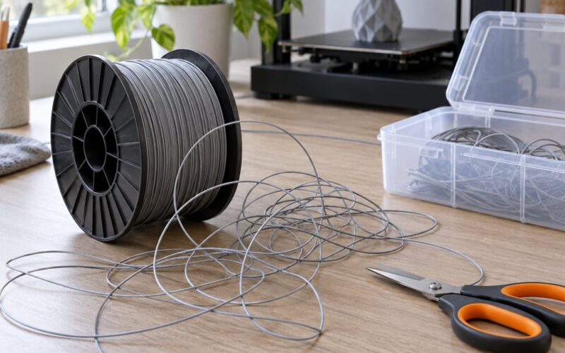
Dry your filament and store it with desiccant. Wet filament causes popping, stringing and poor surface quality, and the wasted spools are a real line item that nobody counts.
7. Test One Change at a Time
Slice your small test model with the baseline settings, print it, and record the time and the grams. Then change exactly one thing and repeat.
Keep the quality checks identical each round. Same first layer, same overhang section, same feature that usually fails. Look for the failure modes you actually get: lifted corners, cracking around holes, stringing, elephant foot, visible seam lines.
If you change three settings at once and the print comes out faster, you have learned nothing about which change did it. If it fails, you have lost the afternoon twice over.
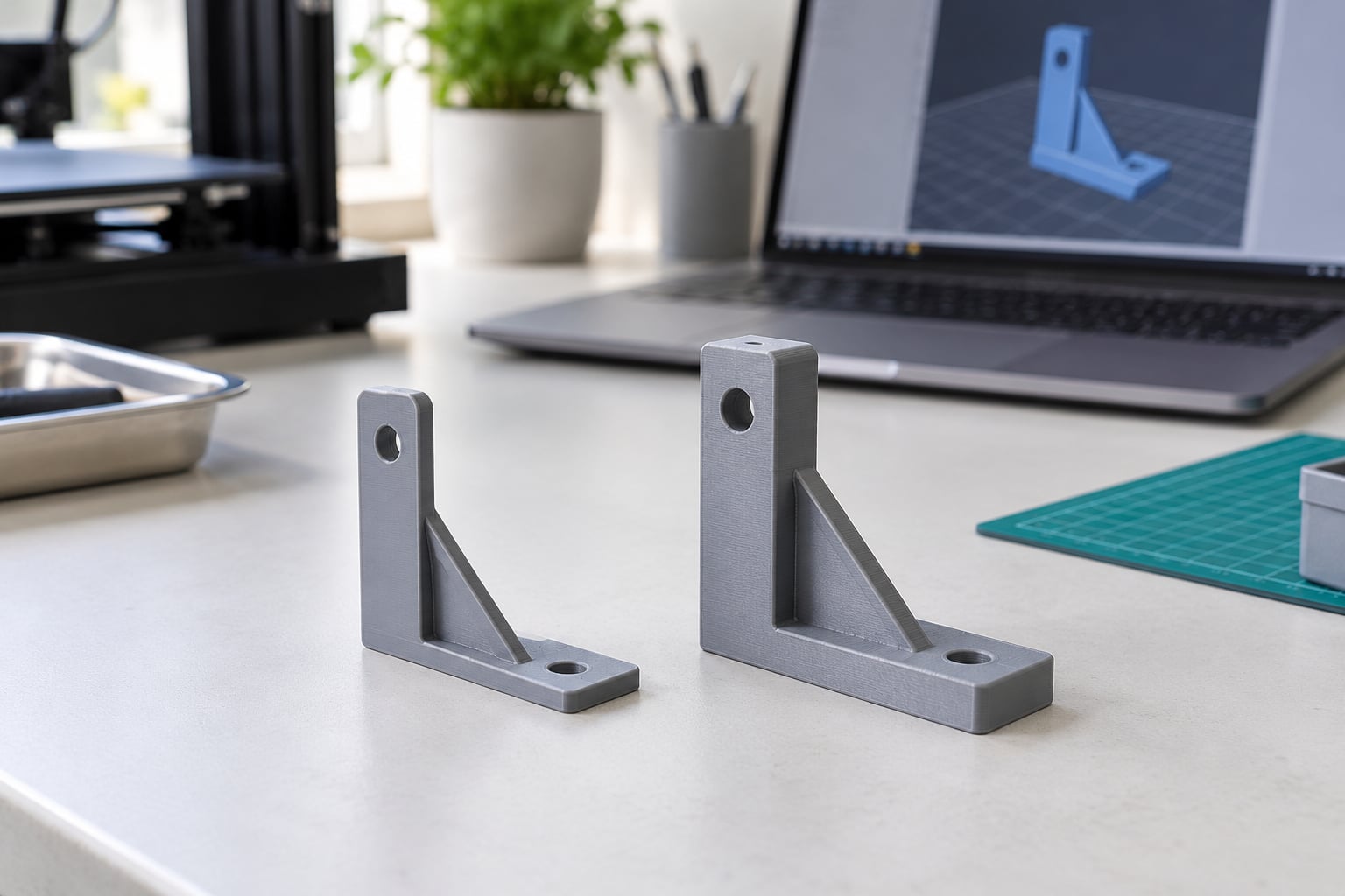
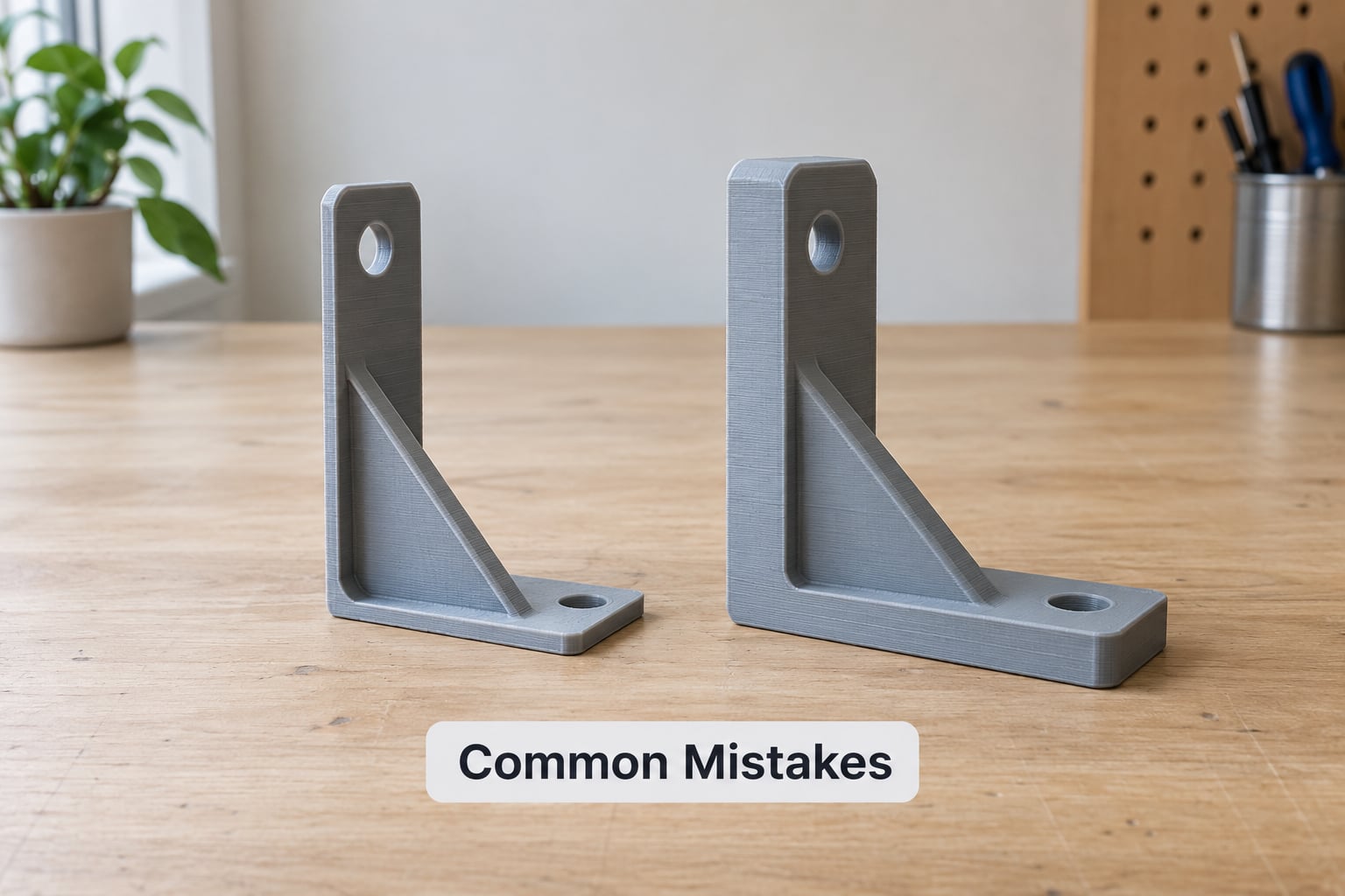
A useful middle ground is the thin-bracket comparison. Print a bracket, measure it across its critical span, and compare the measured dimension against the expected one. Dimensional drift is often the first sign that a wall or layer reduction has gone too far.
8. Save Confirmed Settings as Profiles
Once a combination passes your checks, save it as its own profile and give it an honest name.
Most slicers support something like a Draft, Balanced and Quality set. Draft uses three perimeters, 20% infill and a coarse layer height for anything cosmetic or fit-check-only. Balanced sits in the middle for everyday functional parts. Quality keeps fine layers and full perimeters for display pieces and anything that gets sanded, primed or painted.
Switching profiles becomes a decision instead of a project. You stop re-optimising a part you already solved last month, and your print queue stops carrying settings you guessed at.
Common Mistakes
Lowering every quality setting at once. Thin walls, low infill, coarse layers and full speed together give you a fast print you cannot use. Fix: one change per test print, and keep a quality checklist you actually look at.
Maximising speed to hit a deadline. A print that finishes fast and fails at hour six has cost you six hours. If a part must land by tomorrow, a Balanced profile with a lower infill pattern is a better bet than a Draft profile at top speed.
Thickening everything for strength. Newcomers add walls and infill until a part is heavy and still snaps in the wrong direction. Strength comes from perimeter count and direction, not from raw mass. Fix: keep two or three perimeters, keep infill moderate, and orient so load runs along the layer lines.
Assuming lower infill is always cheaper overall. It is cheaper in grams and slower to fail, but it is a weak time lever on top-solid parts. Fix: get the geometry right first, then decide whether you are optimising for grams or for hours.
Counting filament but not failures. A single failed long print can use more material than a month of careful optimisation saves. Fix: weigh the spool monthly and treat the gap between what you slice and what you finish as your real consumption.
Trusting the slicer estimate. Estimates drift from actual logs. Fix: keep an actual figure for the parts you print often and plan against that.
Two quick habits help more than any single setting. Print more than one part per plate when geometry allows, and let the plate cool fully between parts so you are not fighting warping on the second one.
If you sell prints or quote for others, the same work feeds straight into your machine rate. Shorter jobs and lighter parts raise the number of jobs you can quote in a day, which is where the money actually is.
Frequently Asked Questions
What setting reduces 3D print time the most?
Layer height is usually the biggest single lever, because time scales roughly with the number of layers. Raising layer height toward your nozzle diameter can cut a long job by 20 to 50% on its own. After that, reorienting the model to cut supports and switching to a faster infill pattern usually deliver more than lowering infill density does.
How can I reduce filament use without weakening the print?
Hollow a solid model while keeping two walls and adding drainage holes, reorient to remove supports, fix over-extrusion, and move from three perimeters to two on parts that are not carrying heavy load. Keep your top and bottom layer counts unchanged, since those do more for surface strength than infill does.
Is lower infill always better for reducing material cost?
No. On many top-solid models, perimeters and top and bottom layers dominate both time and filament, so cutting infill from 100% to 20% has saved some users only about 10% of total time. Infill is a good material lever and a weak time lever, and it only pays off properly once the geometry is already sensible.
Should I increase print speed to save time?
Raise infill speed and leave external perimeter speed slower, since the outer surface is the part everyone sees. Avoid blanket maximum speed, because it causes under-extrusion, blistered layers and weak walls. Test any speed increase on a short print before committing a long job to it.
How do I know whether a part is strong enough after reducing walls or infill?
Test on a small version of the same geometry and measure what matters: the critical span dimension, fit, and any fastener location. If the part carries real load, print a coupon at the new settings and load it to the same condition the real part will see. Sliced estimates cannot answer strength questions.
Can support removal reduce material cost without hurting quality?
Yes, and it is one of the cleanest savings available. Reorient the part to remove overhangs first, then switch to tree or organic supports, lower support density, raise the support overhang angle, and set generous interface spacing. Brim and raft are adhesion aids, not support, so keep a brim on tall parts that need it.
Conclusion
Start by measuring one print properly: actual logged time and grams weighed off the spool, not just the slicer estimate. Then reorient the model and hollow it if it is solid, cut one perimeter, try a faster infill pattern, and replace grid supports with tree supports. Test each change on a short print before it touches a long job.
Save whatever survives as a named profile. That, more than any single slider, is what actually reduces print time and material cost over a month of printing.