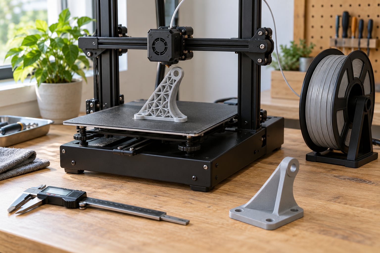
You save material with a lattice by replacing solid bulk with a repeating open-cell network, so material sits only where the load path actually needs it. Most of a solid part is over-provisioned, and taking that redundant volume out cuts filament, resin or powder use while keeping most of the stiffness. Getting there takes seven steps: find the load paths, pick a lattice family, set cell size and strut thickness, generate the geometry, orient it for support-free printing, inspect the print, then test coupons before you commit to a production run.
For most of this guide, “lattice” covers both families: strut lattices built from repeating unit cells with nodes at the junctions, and TPMS surfaces such as the gyroid that divide space with a mathematically smooth sheet.
Updated for October 2026.
Table of Contents
- 1What You Need Before You Start
- 2Design and modelling tools
- 3A process that can actually resolve the struts
- 4Material, measurement and safety
- 5Optional but valuable
- 6How to Use Lattice Structures to Save Material: Step by Step
- 71. Define the part and its load direction
- 82. Choose a lattice type
- 93. Set cell size, strut diameter, and density
- 104. Model or generate the lattice
- 115. Orient the part for support-free printing
- 126. Slice, print, and inspect
- 137. Test and refine before you commit
- 14Common Mistakes That Waste Material Instead of Saving It
- 15Cutting infill too far
- 16Disconnected cells
- 17Ignoring orientation
- 18Unsupported horizontal struts
- 19Sealing cavities that trap powder
- 20Assuming geometry guarantees strength
- 21Forgetting that FDM cannot resolve fine cells
- 22Frequently Asked Questions
- 23How much material can lattice structures save?
- 24Can you 3D print lattice structures?
- 25Are lattice structures stronger than solid?
- 26Is 100% infill stronger than gyroid?
- 27What is the minimum strut diameter for printing a lattice?
- 28Do lattice structures need support material?
- 29Start With One Coupon, Not a Whole Part
What You Need Before You Start
The short answer: a way to model the cell pattern, a slicer that reports material use accurately, and a process whose resolution is finer than your struts. Lattice features are increasingly locked behind paid tiers, so free or open tooling matters, and it is genuinely enough for most first attempts.
Design and modelling tools
Parametric CAD with a lattice generator gives you the most control, because cell size, strut diameter and density stay editable numbers. Grasshopper inside Rhino is the common free-leaning route, and generative or topology optimisation tools in packages like Autodesk Fusion 360, Siemens NX or Altair Inspire will hand you a load-derived shape you then pattern-fill. For a first test, Meshmixer’s pattern tools or a cloud modelling tool with a lattice feature are enough to see whether the geometry survives the process.
You do not need any of that to model a simple lattice by hand. A single unit cell, arrayed and intersected with a solid shell, is the whole trick.
A process that can actually resolve the struts
This is where most designs quietly fail. The commonly cited minimum feature sizes across processes differ by a factor of five, and a strut thinner than your process can resolve will simply not exist in the finished part.
| Process | Minimum feature size (typical published floor) | Design target you should actually use |
|---|---|---|
| DMLS / metal powder bed | 0.3 mm | 0.4-0.5 mm struts, or wider for powder flow |
| SLS nylon | 0.5 mm | 0.6-0.8 mm struts |
| MJF nylon | 0.5 mm | 0.6-0.8 mm struts |
| SLA / DLP resin | 0.3 mm | 0.5 mm struts, 0.2 mm layers |
| FDM filament | 1.5 mm | 1.5-2.0 mm struts, often two extrusion widths |
Read the FDM row again. A 0.4 mm strut is physically impossible on a typical consumer filament printer, and that single fact explains most of the disappointed posts on printing forums. If you own one, your realistic minimum lattice is coarse, with cell sizes in the 8-15 mm range, or you move to resin or send the part to a service bureau.
Material, measurement and safety
Pick a material you already print well rather than experimenting with lattice geometry and a new filament at the same time. You also want a digital caliper or a kitchen scale for measuring mass, a way to record slicer material estimates before and after, and coupons you can load to failure. For resin work, gloves, ventilation and a proper wash and cure routine; for powder-bed processes, dust extraction and whatever handling your equipment requires.
Optional but valuable
Finite element analysis on the solid part before patterning tells you where the stress actually concentrates, which is the single best input to step one. Coupon printing, a force gauge or a simple drop test, and a mesh repair tool for cleaning exported geometry round out the setup.
How to Use Lattice Structures to Save Material: Step by Step
1. Define the part and its load direction
Start with loads, not patterns. Work out what the part carries: bolt loads in tension, bending, torsion, impact, heat, or a flow of air or liquid. Then mark which regions are actually in the load path and which are just filling a bounding box.
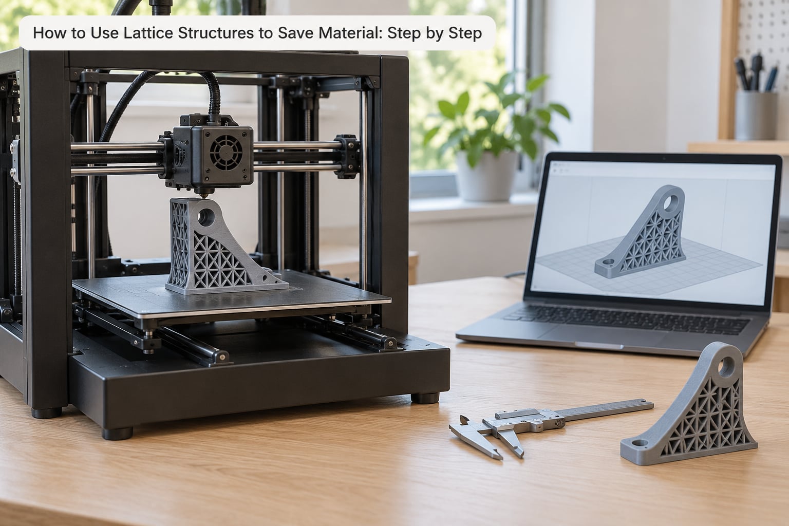
That split gives you three design types. A structural lattice carries real loads and needs a defined relative density and a skin. A non-structural lattice fills space for weight, handling or aesthetics and can be much coarser. A hybrid keeps bolt bosses, bearing faces, threads and mounting pads solid, then puts the lattice between them, and this is the right answer far more often than people expect.
Before you go further, settle the question that derails most beginners: a designed lattice or a slicer infill pattern.
| Criterion | Designed lattice core | Slicer infill pattern |
|---|---|---|
| Where material goes | Where you model it, load by load | Evenly across every interior region |
| Density control | Independent of wall count and shell | One global percentage, plus shell lines |
| Strongest at low density | Octet and diamond, well oriented | Gyroid, among the patterns offered |
| Surface finish | You control the skin | Shell lines only, rough on exposed faces |
| Design effort | Hours, and a real learning curve | A slider |
| Best for | Stiff lightweight cores, flow, heat transfer | Casual parts, prototypes, jigs, handles |
To answer the infill question people ask most often: 100% infill is not simply “stronger” in a way that matters. It is far stiffer per unit mass because it is a solid block, but it defeats the purpose when you are trying to save material. A gyroid at a moderate density carries load in three directions at once, so a 30% gyroid is a reasonable structural choice for a non-critical part, while 10% is generally too sparse for load bearing and fine for spacers, cosmetic shells and draft geometry.
2. Choose a lattice type
Strut lattices and TPMS lattices behave differently, and picking the wrong family is the most common reason a “lightweight” part ends up weak or unprintable.
| Pattern | Family | Where it earns its place | Watch out for |
|---|---|---|---|
| Cubic | Strut | Simple models, compression, teaching | Weak in shear, node stress concentrates |
| BCC | Strut | Good stiffness, simple node logic, easy to generate | Needs a skin or high density to work well |
| Octet truss | Strut | Highest stiffness per unit mass, structural cores | Trillions of cells, so CAD or a lattice tool, not manual modelling |
| Diamond / Kelvin | Strut | Compliance, energy absorption, bone scaffolds | Long thin struts droop on FDM |
| Gyroid | TPMS | Flow, heat exchange, filters, load-bearing infill | Needs decent resolution; surface roughness shows the pattern |
| Schwarz P and Schwartz D | TPMS | Sandwich cores, cushions, midsole foams | Thin sheets print poorly on coarse processes |
| Graded or variable density | Both | Stiff at the loads, light everywhere else | Steep gradients create thin sections that will not print |
As a rough rule, if the part resists compression or bending, look at octet, diamond or BCC. If it moves air, resin or coolant, a gyroid is hard to beat because its surface is one continuous sheet with zero mean curvature. If the part has to absorb an impact, a compliant cell with more deformation room beats a stiff one, which is the entire reason footwear midsoles are printed with lattice or TPMS cores.
3. Set cell size, strut diameter, and density
Three numbers do most of the work. Unit cell size sets how many struts sit across a load path. Strut or wall thickness sets the strength of each member. Relative density sets the overall material fraction of the lattice itself.
Two rules keep you out of trouble. Make the unit cell at least five times the minimum strut diameter your process can resolve, otherwise the geometry gets fragile and the cells stop behaving as designed. And keep the solid skin around the lattice between 0.8 mm and 1.5 mm, because that skin is what handles surface finish, handling loads and any impact the part sees.
Move strut diameter before you move cell size. Thicker struts raise strength and stiffness quickly at a modest material cost, and they make the print far more reliable. Cutting cell size too far is where savings turn into scrap.
For the last increment of savings, grade the density. Solid and dense where the load enters, open and light where it does not. Commercial work often finds a further 10-15% on top of a uniform lattice this way, but keep the gradient gentle; a cell that thins faster than your process can build is a cell that disappears.
4. Model or generate the lattice
There are three routes and they suit different people. Manual CAD: model one unit cell, array it to fill the volume, intersect with the solid boundary, and trim. Parametric: define cell size, strut radius and density once, then change them as a variable. Generative: let topology optimisation propose the load-carrying shape, then fill it with a lattice and add a skin.
Whichever route, the finishing steps are the same. Trim the lattice back so it stops short of bolt holes, threads and bearing faces rather than filling them, since a lattice stub inside a tapped hole will crack the first time it is loaded. Keep a solid wall between the lattice and any face that gets handled or seen. Check the exported mesh for disconnected cells, which print as loose fragments, and for self-intersections that make the slicer produce nonsense.
For powder-bed processes, add drain holes of roughly 2 to 3 mm wherever unsintered powder could sit trapped, and orient the part so gravity helps. Unsintered powder in a closed cell is not a cosmetic problem; it is a scrap part and sometimes a safety issue.
5. Orient the part for support-free printing
Orientation decides whether the lattice prints or melts. Struts that run more than about 45 degrees off the build plate self-support in most processes; shallower ones droop into each other and close the cell. So tilt the part rather than the individual struts whenever you can, which usually means picking a different face as the base.
Align the main load direction with the strongest part of the pattern. An octet lattice is far stiffer along its principal direction than across it, so printing a bracket with its high-load axis in the weak direction wastes material and buys nothing.
Process specifics differ, so treat these as starting points rather than rules. On FDM, keep struts at two extrusion widths minimum, raise the number of perimeters on the skin, and expect a coarse pattern. On resin, the constraint is different: uncured resin is the enemy, so make sure the part drains and cures fully, and consider a draft angle on downward-facing internal features. On SLS and DMLS, powder removal matters more than overhang angle, because trapped powder is the thing that ruins the part.
6. Slice, print, and inspect
Before printing, read the slicer estimate for material and time and write it down. That number is your before-picture, and it is how you prove the design saved anything.
During slicing, keep the outer perimeters high on structural parts, since the perimeters are what carry bending loads at the surface. Do not let the slicer reduce infill below the density you designed, because a lattice core with a 10% infill is not the lattice you calculated.
When the part comes off the printer, look for three things. Missing or fused struts tell you the cell size or strut diameter is below what your process can hold. Open cells that should be closed tell you skin or wall thickness is short. Powder or support residue inside cavities tells you your drain strategy failed, and it is worth fixing before the next run rather than after a customer finds it.
7. Test and refine before you commit
Do not skip this. Print a small coupon of the lattice next to an equivalent solid coupon, weigh both, and load them. You are looking at mass, stiffness, where the failure starts, and whether the part holds or simply deforms and cracks at a node.
Then change one thing at a time. Thicken struts if stiffness is short and mass is not a problem. Reduce cell size if the part is too soft for its purpose. Change pattern if the failure mode is shear rather than bending. Add solid material at the load entry if cracks start where the load transfers into the lattice, which is a very common result and an easy fix.
The lightest design is not the best design. The best design is the lightest one that meets your stiffness and strength requirement, and only a coupon tells you which density that is.
Common Mistakes That Waste Material Instead of Saving It
Almost every failed lattice has one of these causes, and each one has a specific fix.
Cutting infill too far
Dropping a part from 40% infill to 10% to save filament usually produces something that flexes like a shell and snaps at the first real load. Fix it by thickening the lattice struts or reducing cell size rather than thinning everything at once, and keep the skin at full thickness.
Disconnected cells
A cell that does not connect to its neighbour is a piece of scrap that still consumes material, powder and time. It also weakens the load path, so the part is both heavier and weaker than designed. Fix it in CAD by checking the exported mesh for loose bodies before you send it to the slicer.
Ignoring orientation
The most common reason a lattice part is weak in real use is that it was printed in whichever direction the part happened to sit in. Lattices are anisotropic; print with the load along the strong axis, and if that means a tilted build plate and a small support raft, take the raft.
Unsupported horizontal struts
Struts that sit flat in the air droop, and the cells close up. On FDM this wrecks the pattern in one or two layers and the damage compounds. Fix it by tilting the part so struts clear the 45 degree rule, or switching to resin for fine work.
Sealing cavities that trap powder
A closed cell with no exit path holds unsintered powder indefinitely, and it will not show up on the outside of a finished part. Fix it with 2 to 3 mm drain holes on the low side and an orientation that lets powder fall out.
Assuming geometry guarantees strength
A beautiful lattice can still be a bad part. Strut junctions concentrate stress, and under repeated cyclic loading that is where fatigue cracks usually start. If the part sees vibration or cyclic load, add a skin, round the node region, or move to a pattern with more uniform load paths, then verify with a coupon rather than an assumption.
Forgetting that FDM cannot resolve fine cells
A 0.4 mm strut in the model on a consumer filament printer prints as a rounded smear or nothing at all. Fix it by scaling the cell up until it is printable, by moving to resin, or by budgeting for a service bureau. Do not spend four attempts discovering this.
Frequently Asked Questions
How much material can lattice structures save?
Well-designed lattices typically come in 30 to 70 percent lighter than a solid equivalent, and reported material cost reductions run around 40 to 60 percent. Real savings depend on the application: a structural core with a solid skin saves less than a fully open non-structural filler, and a graded lattice can add a further 10 to 15 percent over uniform density. Measure your own before-and-after figures from the slicer.
Can you 3D print lattice structures?
Yes, on any process, but the resolution sets the pattern you can get. Resin and metal powder bed can hold struts around 0.3 mm, SLS and MJF manage roughly 0.5 mm, and FDM needs 1.5 mm or more. That gap is why fine lattices fail on home filament printers. Design the cell size and strut diameter for the process you actually have, not for the screen.
Are lattice structures stronger than solid?
Not in absolute terms. A solid block is stiffer and stronger for the same material, because it has no discontinuities. The comparison that matters is strength or stiffness per unit of mass, and lattices win there because material is placed along the load paths. A solid part made to match a lattice’s weight will be far stiffer than the lattice but much heavier, which defeats the purpose.
Is 100% infill stronger than gyroid?
100% infill is a solid block, so it is far stiffer and stronger in absolute terms than a gyroid at any density. It is also much heavier, which is usually the whole point. A gyroid at a moderate density carries load in three directions at once and is a sensible structural infill, while 10 percent is generally too sparse for anything load bearing. Pick based on the job, not on the percentage.
What is the minimum strut diameter for printing a lattice?
Commonly cited minimum feature sizes are 0.3 mm for DMLS and for SLA or DLP resin, 0.5 mm for SLS and MJF, and 1.5 mm for FDM. Design above those floors rather than at them: 0.4 to 0.5 mm struts in metal, 0.6 to 0.8 mm in powder-bed nylon, and 1.5 to 2.0 mm in filament. Also keep the unit cell at least five times the minimum strut diameter.
Do lattice structures need support material?
A correctly designed and oriented lattice should need very little. The rule of thumb is that struts more than about 45 degrees off the build plate self-support in most processes, so if a lattice needs a forest of supports, the orientation is wrong rather than the design. In powder-bed processes, support is rarely the issue; trapped unsintered powder is, which is why drain holes and a good orientation matter more.
Start With One Coupon, Not a Whole Part
If you only do one thing from this guide, take a small part you have already printed, note the slicer’s material estimate, and rebuild it as a hybrid: solid bolt pads with a lattice core and a skin between them. Print it, weigh it against the original, and load it. That one comparison teaches you more about your own printer’s limits than any specification sheet.
After that, work outward in order. Get a coarser cell printing cleanly, then tighten the pattern, then grade the density. Save the aggressive designs, the graded lattices and the octet cells for the moment when a part is already printing well. That is how to use lattice structures to save material without spending the savings on failed prints.