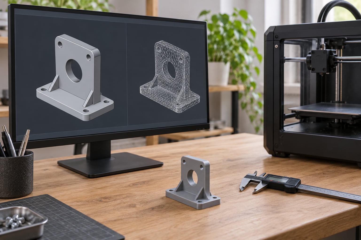
To use FreeCAD for mechanical parts, you sketch a 2D profile, constrain it until nothing can move, then extrude that sketch into a solid and cut, pattern and fillet it before exporting STL or 3MF for printing. FreeCAD is free, runs on Windows, macOS and Linux, and keeps every dimension editable, so a change to one number rebuilds the whole part instead of forcing you to model it again.
That parametric history is the whole point. A part modelled in a mesh editor gives you a finished shape with no memory of how it got there. A part modelled in FreeCAD gives you a tree of features you can walk back into, which matters the first time the print does not fit and you need to change a hole from 3.2 mm to 3.6 mm at midnight.
Allow two to three hours for your first functional part, and expect the first hour to go almost entirely into learning the Sketcher. The commands are named plainly, but the constraint solver asks for a different way of thinking than freehand drawing. Below is the workflow I would teach someone sitting down for the first time.
Table of Contents
- 1What You Need
- 2Which CAD should you use for the part?
- 3Step-by-Step: how to use FreeCAD for mechanical parts
- 41. Define the part and choose a printing method
- 52. Create a FreeCAD document and select the workbench
- 63. Make a fully constrained base sketch
- 74. Extrude the profile into a solid
- 85. Add pockets, holes and mechanical features
- 96. Validate, export and test the part
- 10Common mistakes
- 11Frequently Asked Questions
- 12Is FreeCAD suitable for beginners making mechanical parts?
- 13What file should I export from FreeCAD for 3D printing?
- 14How do I choose the right clearance for a printed mechanical part?
- 15Can I make an assembly of multiple FreeCAD parts?
- 16What is the difference between STL and STEP files?
- 17Do I need to know engineering drawing or CAD terminology to use FreeCAD?
- 18Conclusion
What You Need
You need FreeCAD itself, the measurements of the real part you are reproducing, and a clear idea of how the finished object will be made. Everything else is optional.
FreeCAD downloads from the official project site as an installer for Windows and macOS and as packages for most Linux distributions. There is no paid tier and no account to create. The program is released under the LGPL licence, which means you can use it commercially and modify it.
Alongside the program, gather the real dimensions of whatever you are modelling: the mounting hole spacing, the shaft diameter, the wall thickness of the enclosure it has to sit inside. If the part mates with something you already own, measure that item with calipers rather than trusting the drawing. Printed parts fit to the model, and the model can only be as right as the numbers you put in.
Decide the manufacturing process early. FDM printing rewards ribs over thick walls, tolerates slight interference, and hates overhangs past roughly 45 degrees. Resin printing gives finer detail but needs supports and a different tolerance mindset. Machining a printed model needs clearance on every hole. A quick FEM stress check inside FreeCAD is worth running for loaded brackets, though the numbers need a caveat I will come back to.
Menu names shift slightly between FreeCAD releases. The examples below use the standard Sketcher and Part Design workbenches that ship with the program, and version 1.0 reorganised the Assembly workbench, so expect small differences in toolbar position rather than in command names.
Which CAD should you use for the part?
FreeCAD is the sensible default for printable hobbyist parts because it costs nothing and stays out of the way. The comparison below is the honest comparison, not the marketing one.
| Program | Cost | Operating systems | Parametric depth | Best for |
|---|---|---|---|---|
| FreeCAD | Free, open source, LGPL | Windows, macOS, Linux | Full feature tree with spreadsheet expressions | Printable brackets, enclosures, jigs and one-off replacement parts |
| Fusion 360 | Free for personal use, commercial terms apply | Windows, macOS | Full, timeline based | Users who want a polished guided interface and cloud collaboration |
| SolidWorks | Paid subscription | Windows only | Full, industry standard | Professional mechanical work in a commercial office |
| Onshape | Free tier, paid upgrades | Browser based, works anywhere | Full, cloud documents | Collaborating with people on different machines |
The comparison table matters because the common question is whether FreeCAD can replace commercial software. For mechanical parts you intend to print at home, it can and the alternatives offer nothing you will use. For a professional assembly that has to pass a review, the commercial tools still have better drawing output, simpler constraint handling and support contracts.
Step-by-Step: how to use FreeCAD for mechanical parts
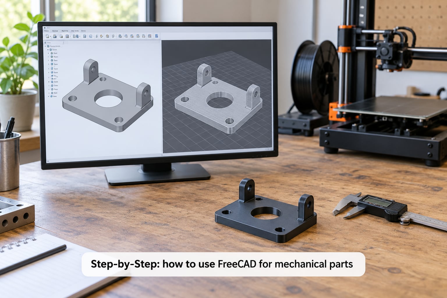
The workflow below takes a mounting plate from a blank document to an exported file. Follow it in order and the model stays recoverable at every stage.
1. Define the part and choose a printing method
Before opening the program, write down what the part has to do. For a mounting plate that is the plate length and width, the material and wall thickness, the number and size of bolt holes, their spacing, whether anything presses against the plate face, and the load the bolts carry.
Those answers become design constraints. A 4 mm hole for an M3 bolt needs clearance, not the nominal 3 mm. A plate standing on edge needs a fillet at the base rather than a sharp internal corner, because a sharp corner concentrates stress in the plastic and in the layer lines. A part that must slide over a rod needs its hole dimensioned larger than the rod.
Settle orientation before you model. Lay the largest flat face against the bed so layer adhesion runs along the main load path. Add ribs instead of thickening a wall if stiffness is the goal, since ribs print faster and weigh less. Decide now whether the part needs support material, because designing it to avoid support costs nothing at this stage and saves cleanup later.
2. Create a FreeCAD document and select the workbench
Open FreeCAD, choose File and New to create a document, then switch the workbench selector at the top of the screen to Part Design. With a body selected, press Create body to add a Body to the tree.
The Body is where your solid lives. Every sketch and every feature you create goes inside it, which is what lets later features reference the faces earlier ones created. If you see features sitting loose in the document tree instead of under the Body, drag them inside.
Part Design is additive and subtractive: you build up material with Pad, Loft, Sweep and Revolution, then remove it with Pocket, Groove and Hole. That is the opposite of the Part workbench, where you import primitive shapes and cut them with booleans. Both produce valid geometry, but Part Design keeps a history you can edit later, so it suits mechanical parts. Use the Part workbench only when you are handling imported shapes or doing analysis of someone else’s file.
Work in millimetres and degrees. FreeCAD lets you change the measurement system under Edit and Preferences, General and Units, and switching to the metric system avoids surprise fractions entering a model.
3. Make a fully constrained base sketch
Select a face or an origin plane in the tree, then use Part Design and Create sketch. The Sketcher opens with a grid and a solver running in the background.
Draw the profile with the line, rectangle, circle and arc tools. Keep profiles closed, because a Pad needs a closed wire and an open one will throw an error instead of extruding.
Now constrain it, and this is the part beginners rush. Sketch and Sketcher constraints divide into two families. Geometric constraints control how geometry relates to other geometry: horizontal, vertical, coincident, tangent, parallel, symmetric, equal. Dimensional constraints set actual numbers: distance, radius, diameter, angle. Dimensional constraints are the ones that make the model parametric, so use real numbers there rather than dragging geometry into position.
The solver reports remaining degrees of freedom in the task bar. Start from fully unconstrained, add constraints until the counter reads zero, and the sketch turns green and fully constrained. An under-constrained sketch still extrudes, which is the trap: it looks right on screen and then drifts the next time you edit an unrelated feature, and the solid you print no longer matches the model you approved.
Symmetry and equal constraints are what let you place four holes from one dimension. Constrain one hole fully, mark the other three symmetric or equal to it, and one number drives all four.
4. Extrude the profile into a solid
Close the sketch, select it in the tree, and choose Part Design and Pad. The Pad dialog offers several types. Length is a single value. ThroughAll pushes the extrusion past everything in the way. TwoLengths gives one value each way from the sketch plane. Midplane centres the pad on the sketch, and Reversed flips the direction when the solid grows the wrong way.
If your pad points backwards, do not delete it and start over. Toggle Reversed in the dialog, which updates the model immediately.
Check the result by switching the tree view to the Body and looking at the solid’s edges. A good first habit is to hide the sketch afterwards so you can judge the shape without hidden lines crossing it.
5. Add pockets, holes and mechanical features
Select the top face of the pad and create a new sketch on it. Sketch the feature you want to remove, then choose Part Design and Pocket with ThroughAll or a Length.
For repeated holes, use the Hole tool rather than drawing circles. Select a sketch containing circles, open Part Design and Hole, and the dialog takes a thread standard, a diameter and a depth directly. That keeps hole sizes in one place where you can adjust them once instead of editing eight sketches.
Pattern anything repeated. Part Design and LinearPattern multiplies a feature along a direction with a given spacing and count, and PolarPattern spreads copies around a centre for a bolt circle. Patterns reference the original feature, so changing one hole updates every copy.
Break your sharp edges. Part Design and Fillet rounds an inside corner, which is where stress concentrates and where a printed part cracks first. Chamfer gives you a lead-in for assembly or a chamfered edge that will not cut your hands on a hand tool.
Consider the printed mounting plate as a worked example. Sketch a 60 mm by 40 mm rectangle with the corner radius constrained, add four circles on a 45 mm by 25 mm pattern, close the sketch and Pad it 5 mm. Sketch a 20 mm circle centred on the plate and Pocket it 2 mm for a recess. Draw one circle, cut it with Hole on an M3 clearance size, then LinearPattern it 150 mm to place three more. Finish with a 2 mm Fillet at the base of the wall.
Add a rib to that plate and you will notice the difference between a flat part and a functional one. Ribs 2 to 3 mm thick and as tall as the wall give far more stiffness per gram than a thicker slab.
6. Validate, export and test the part
Force a rebuild with Edit and Refresh, then read the tree. Any feature carrying a warning marker or an exclamation icon failed to recompute, and a silent failure here exports a broken file without complaining.
Use Measure to check the dimensions that matter: hole diameters, the distance between hole centres and the overall thickness. Compare those against what the part has to fit into.
Then export. Select the Body, choose File and Export, and pick the format your slicer wants.
| Format | What it stores | Use it for |
|---|---|---|
| STL | A triangle mesh with no parameters, colours or units | Slicing and printing, when your slicer accepts nothing else |
| 3MF | Mesh plus colour, material and unit metadata | Multi-part prints and colour assignment |
| STEP | Exact solid and surface geometry | Sending to a machinist, or opening in another CAD program |
Export STL with the mesh deviation set coarse enough that the file stays small. A fine deviation on a simple plate can produce a mesh heavy enough that the slicer struggles, which is a common source of the slow exports people report.
Open the result in your slicer and look at it before printing. Rotate the view and check layer lines, supports and overhangs. Then print a small test section, or the whole part if it is small, and test the fit against the real mating part before committing to a full print.
If you want to check strength before printing, FreeCAD has an FEM workbench that applies constraints and loads and runs a static analysis through the CalculiX solver. Treat the von Mises stress numbers as a relative comparison between two versions of your own part rather than an absolute prediction, because a printed solid is built from anisotropic layers that a standard isotropic material model does not describe.
Common mistakes
Almost every FreeCAD failure that reaches a print comes down to a small number of causes. The table pairs each symptom with its cause and the fix, and the list afterwards covers how to avoid them in the first place.
| Symptom | Cause | Fix |
|---|---|---|
| Sketch stays red, degree-of-freedom counter will not reach zero | Missing dimensional constraints, or two constraints fighting each other | Add distance or radius constraints instead of dragging geometry, and delete any constraint marked as redundant or conflicting |
| Pad extrudes the wrong way or produces nothing | Sketch on the wrong plane, or profile not closed | Toggle Reversed, and check every line end has a coincident constraint joining it to the next |
| Pocket fails with a self-intersection error | Profile crosses the sketch plane or overhanging material | Redraw the profile so it does not overlap itself, and confirm the pocket direction with Reversed |
| Holes print too tight for the bolt | Modelled at nominal diameter with no allowance | Add 0.3 to 0.5 mm to the modelled diameter for a printed clearance fit and check with a test piece |
| Solid reports non-manifold or import fails | Coincident faces from booleans, or a solid with an internal void | Run Part and Shape and Check geometry, and rebuild the offending feature rather than patching the imported result |
| STL export takes minutes or appears to hang | Mesh deviation set very fine, or a complex feature history | Raise the deviation, simplify unnecessary fillets and threads, and export the Body rather than the whole document |
| Part delaminates or snaps at a corner after printing | Sharp internal corner and layer adhesion running across the load | Add a fillet and reorient the part so layers run along the stress path |
| Overhangs come out stringy and rough | Steep unsupported surfaces | Rotate the part on the bed, add a chamfer or rib to bridge the gap, or accept support material |
Four habits prevent most of these. Name every feature and body so the tree stays readable when it grows past a dozen entries. Keep one spreadsheet driving your main dimensions, then bind features to it with expressions so a single cell changes the whole part. Resist adding a fillet that no one needs, since each one is another surface for the slicer to resolve. And save before every risky operation, because the parametric history means a bad edit can be undone in seconds while a manual fix takes an hour.
Frequently Asked Questions
Is FreeCAD suitable for beginners making mechanical parts?
Yes, for printable mechanical parts it is one of the best starting points, because it costs nothing and runs on Windows, macOS and Linux. Expect a real learning curve in the Sketcher over the first few sessions, not in the modelling commands. People regularly print a working wrench after about an hour of tutorial time, and the parametric history means a mistake early on costs minutes rather than hours.
What file should I export from FreeCAD for 3D printing?
Export STL or 3MF, not STEP. Select the Body in the tree, choose File and Export, pick your format and set the mesh deviation coarser for a faster file. 3MF carries colour and material metadata, so use it for multi-colour or multi-part prints. If you are sending the design to a machinist or another engineer, export STEP instead.
How do I choose the right clearance for a printed mechanical part?
Add 0.3 to 0.5 mm to the nominal hole diameter for a sliding or bolt clearance fit on a typical FDM printer, more for resin and less for a well-tuned machine. For a press fit, model slightly under nominal and rely on the slicer and material to close the gap. Print a small coupon with two or three diameters before committing, because printer calibration matters more than any rule of thumb.
Can I make an assembly of multiple FreeCAD parts?
Yes. Version 1.0 introduced a built-in Assembly workbench where you insert parts or bodies and constrain them with joints such as fixed, revolute and slider. It works best when the parts come from your own parametric models. Imported STL meshes can be joined into an assembly for positioning, but they carry no editable geometry, so plan on remodelling anything you need to change.
What is the difference between STL and STEP files?
STL stores only a triangle mesh, the same shape data a slicer needs, with no dimensions, features or parameters. STEP stores the exact solid and surface geometry of the part, so another program can open it as a real CAD body. Use STL or 3MF to print, STEP to exchange designs with a machinist or another CAD package, and keep the native .FCStd file as your working master.
Do I need to know engineering drawing or CAD terminology to use FreeCAD?
You need very little to start. The useful vocabulary is small: sketch, constraint, body, feature, pad, pocket and fillet, plus the difference between nominal and clearance dimensions. The Sketcher is where most beginners pause, and that is because constraints describe intent, not appearance. If you can explain what a hole diameter and a centre-to-centre distance mean in millimetres, you can learn the rest while modelling.
Conclusion
Start by writing down the dimensions and the printing constraints before you open FreeCAD at all. Then build one fully constrained sketch and one solid, confirm it recomputes without errors, and only after that add pockets, hole patterns and fillets.
Validate each dimension with the Measure tool, check the exported file in your slicer, and print a test piece before a full run. Careful validation and one test print prevent most failed mechanical parts, and keeping the .FCStd file intact means your next version is a number change rather than a new model.