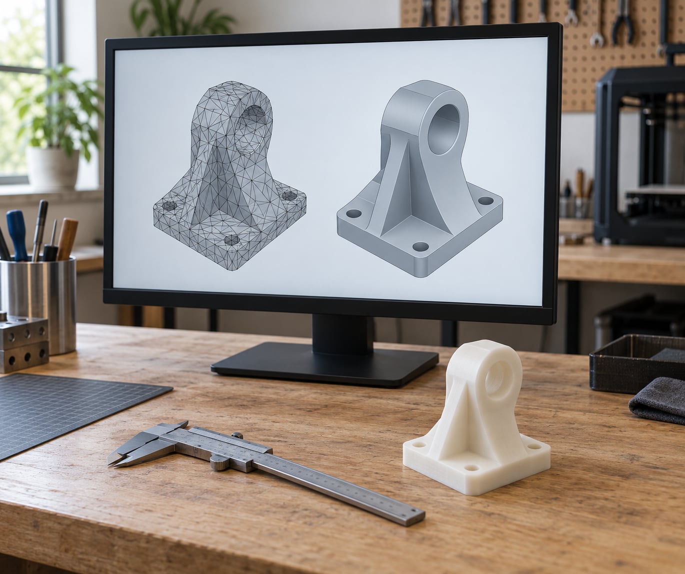
How to convert STL to STEP for CAD editing comes down to five things: import the mesh, confirm its real-world size, repair the defects that block solid conversion, turn the mesh into a boundary-representation solid, then export and re-open the result to check it. On a clean mechanical part that takes ten or fifteen minutes in FreeCAD. A scanned or organic model can eat an entire afternoon, and the triangles you end up with stay in the STEP file.
Before you start, know what you are getting. The result is a faceted solid with no parametric history, so you can cut it, fillet it and boolean it, but you cannot change a dimension and watch the model rebuild. If the original part exists somewhere as a native CAD file or a vendor STEP, get that instead. Conversion is the fallback, not the first move.
Table of Contents
- 1What You Need
- 2The Conversion Choices That Matter Most
- 3Step-by-Step: How to Convert STL to STEP for CAD Editing
- 41. Inspect and prepare the STL file
- 52. Choose a CAD tool and conversion mode
- 63. Repair or optimize the mesh
- 74. Convert the STL geometry into editable CAD geometry
- 85. Check scale, units, and shape accuracy
- 96. Export and verify the STEP file
- 10Common Mistakes
- 11Frequently Asked Questions
- 12What is the best way to convert STL to STEP for CAD editing?
- 13Can FreeCAD convert STL files to editable STEP solids?
- 14Why does my converted STEP file look faceted or contain holes?
- 15Are STL and STEP files measured in millimeters?
- 16Should I repair the STL before converting it to STEP?
- 17How do I preserve the original scale when exporting STL to STEP?
- 18Conclusion
What You Need
The bare minimum is an STL file, a CAD program that can rebuild geometry from a mesh, and ten minutes. Everything beyond that depends on what you intend to do with the STEP once it exists.
- The source STL. Preferably the highest-resolution export you can find, with a known dimension you can measure against. A screenshot of the part with one labelled measurement is enough.
- A CAD program. FreeCAD does the whole job for free. Fusion 360 and SolidWorks do it better on complex mechanical geometry, and both gate parts of the workflow behind a paid tier. Blender is useful for mesh repair but has no native STEP export.
- A mesh repair tool. MeshLab and Meshmixer both handle holes, non-manifold edges and stray geometry. FreeCAD has a repair option built into the mesh conversion dialog, and it handles small defects fine.
- Unit information. STL carries no unit metadata, so the importer guesses. Know the real size of the part in millimetres or inches before you convert anything.
- Reference geometry (optional). A drawing, a photo with a ruler in frame, or the original slicer preview tells you the finished size and whether the orientation is right.
The Conversion Choices That Matter Most
Almost every failed conversion comes down to four decisions made in the wrong order: whether to go solid or surface, how hard to run mesh repair, whether the mesh is too dense to process, and what to check before export. Get those right and the rest is clicking through menus.
FreeCAD takes the shortest path and costs nothing. Import the STL, run Part > Create shape from mesh, convert to solid, refine, export STEP. It is the recipe most people land on because it always exists and never asks for a subscription.
Fusion 360 can produce cleaner geometry on mechanical parts, but Mesh to BRep wants face groups first, and the useful conversion options sit in the paid tier. Plan on merging groups by hand when the automatic guess is wrong.
SolidWorks needs the FeatureWorks add-in for mesh-to-surface work, and the version of FeatureWorks you get decides what you can do. Basic mesh inspection is built in.
Blender is a mesh editor, not a conversion tool. It is useful for scale checks, decimation and organic cleanup, but it will not hand you a STEP file.
Online converters handle small, non-confidential parts quickly. You upload the file, get a STEP back, and have no visibility into how scale was interpreted or whether the mesh was repaired.
Step-by-Step: How to Convert STL to STEP for CAD Editing
1. Inspect and prepare the STL file
Open the file before you convert it. In FreeCAD, use the Measure tool; in Fusion, the Inspect menu on a mesh body; in Blender, Numpad-period for a front view plus the scene rulers.
Confirm three things:
- It is the right part and right orientation, not a mirrored or half-scaled export.
- You know its real size. Measure a feature you know the dimensions of. If the model came off a 3D scan of a real object, measure that object too and write the numbers down.
- The triangle count is workable. Free CPU-based converters start to crawl somewhere past a few hundred thousand triangles. Check the face count in your mesh tool, and decimate first if it is huge.
Look for open edges, isolated floating fragments, and thin sliver faces. In MeshLab, run the standard quality checks; anything reported as non-manifold will block solid conversion later.
How to verify: the measured dimension matches the real part within a millimetre or two, and no repair prompts have appeared yet.
2. Choose a CAD tool and conversion mode
There are four conversion modes, and picking the wrong one is why files come out unusable.
- Import as mesh only gives you the triangle mesh, unchanged. Use it when you only need to inspect, scale or decimate before handing off to another tool.
- Mesh to solid gives a closed faceted B-Rep solid. It suits mechanical parts with flat faces and prismatic features.
- Surface wrapping gives a quad or triangle shell that matches the outer skin. Reach for it on scanned, organic or sculpted geometry where mesh-to-solid genuinely fails.
- Dedicated STL-to-CAD reconstruction fits best-fit analytic surfaces and sometimes parametric features. Worth it when you need clean geometry for CNC or a redesign, and you accept the time cost.
If you only need a watertight solid you can slice and machine, mesh-to-solid is enough. If you need smooth surfaces for moulding or rendering, a faceted solid will look wrong no matter how well it converted.
How to verify: you can state in one sentence what the converted file is for. If you cannot, go back and pick the mode deliberately.
3. Repair or optimize the mesh
Repair only what actually blocks conversion. Aggressive smoothing is the most common way people damage a model while trying to help it, and it changes your dimensions.
- Close small holes with a fill operation sized to the defect, not the whole part.
- Delete isolated components — stray triangles floating off the surface.
- Merge nearby vertices within a tolerance smaller than your smallest real feature.
- Fix self-intersections where the mesh folds through itself. These are the usual reason a solid conversion refuses to run.
- Reduce triangles where it helps. Decimate before converting a very dense scan, and stop as soon as edges look slightly soft.
Skipping smoothing entirely is usually right for printed parts. A 0.2 mm layer-height FDM model already has a stepped surface, and smoothing only removes detail you wanted.
How to verify: a manifold check reports no boundary edges or non-manifold edges, and your earlier measurement still reads the same after the repair run.
4. Convert the STL geometry into editable CAD geometry
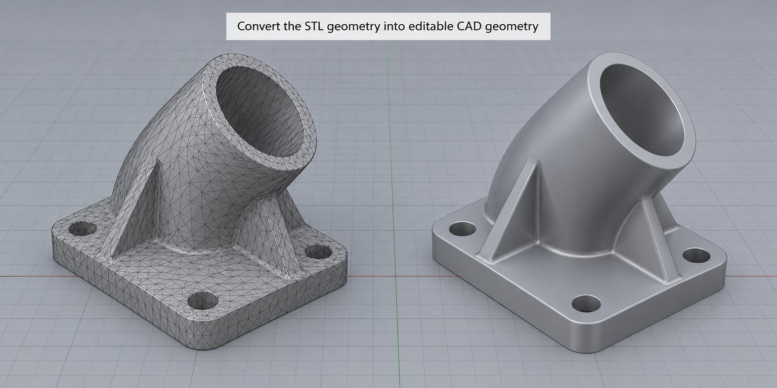
FreeCAD, Part workbench: open the STL with File > Open, then Part > Create shape from mesh. Tick the sewing and refine options for small holes. Select the mesh, then Part > Convert to solid. Make a copy of the result and run Part > Refine shape to clean up the seams sewing leaves behind.
Fusion 360: upload the mesh, switch to the Mesh workspace, and use Mesh > Create Face Groups on each flat region of the part. Select the groups you want merged, run Combine, then Convert > Mesh to BRep. Choose the surface representation setting that matches your geometry, and confirm when some groups will not combine as created.
SolidWorks: check the file with Tools > Import Diagnostics first, which flags gaps and bad faces without changing anything. With FeatureWorks available, use the mesh-to-surface options, then knit the surfaces into a solid body and check the result in FeatureManager for a single closed body.
Inspect the outcome before going further. Look for gaps along the seams, faces the converter inverted, and pinched regions where a faceted surface collapsed.
How to verify: the body measures correctly, has one solid, and no free or open edges show up in the geometry check.
5. Check scale, units, and shape accuracy
STL stores no units, so the importer picks one and tells you nothing. This is the most common real-world bug in the whole workflow: a part that came out 25.4 times too big, or so small it measures in fractions of a millimetre.
Three checks, in order:
- Measure a known feature in the converted solid and compare it to the real-world measurement from step 1.
- Confirm the document units match the file. In Fusion this is Document Settings > Units; in FreeCAD it is the unit shown next to every dimension field.
- Check origin, orientation and bounding box so the part sits where your downstream tooling expects it, not offset or flipped.
If it is wrong, apply one uniform scale at the document level rather than scaling the body. A uniform scale keeps the topology valid, which a non-uniform one does not.
How to verify: the measured dimension matches the real part, and the bounding box agrees with the overall size you expect.
6. Export and verify the STEP file
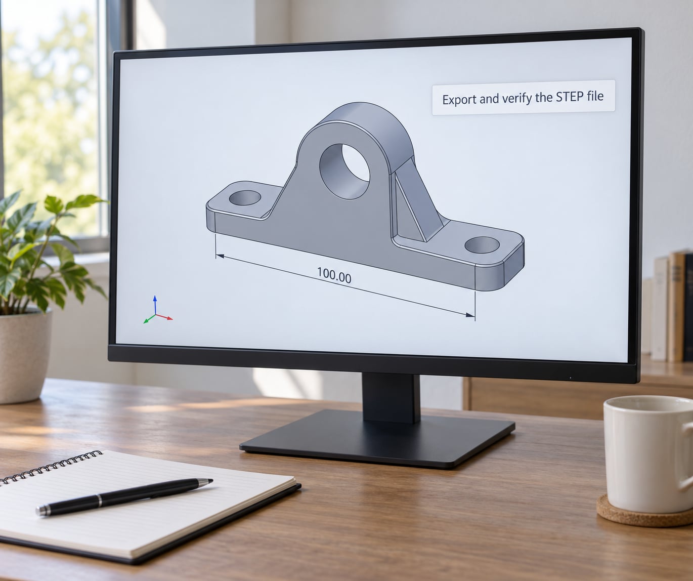
In FreeCAD, use File > Export and pick STEP with the AP214IS schema. In Fusion, Export > STEP with AP214 unless your downstream system asks for AP242. In SolidWorks, Save As with STEP AP242 or AP214.
Schema choice matters more than most guides admit. AP203 is the older baseline and interoperates widely. AP214 adds colour, naming and assembly data, and is the safe default for most work. AP242 is the current standard with tighter data and better handling of machined features, worth using when the receiving end supports it. Ask whoever will open the file if you are unsure.
Re-open the exported STEP in a clean session, or a different program entirely. A file that only opens correctly in the session that created it has a problem.
How to verify: the re-opened file shows one solid at the right size, units are what you expect, and no geometry is missing.
Common Mistakes
Units get lost. STL has no unit metadata, so a 100 mm part can import as 100 inches. Measure a known feature before export and set document units explicitly rather than trusting the import.
You get a surface, not a solid. The conversion stopped at shape or shell level. Run the convert-to-solid step explicitly, and check that sewing was enabled so open edges get closed first.
Open edges and holes. These come from the source mesh, not the converter. Fill the holes in a mesh tool, keeping the fill tolerance small so you close defects without flattening real features.
Self-intersections. A folded mesh has geometry passing through itself, and no converter will build a solid from that. Fix the intersections in mesh editing software, or decimate first if the file is dense enough that the fold is a tessellation artefact.
Over-smoothed geometry. Smoothing after the fact rounds corners you needed. Repair holes, remove fragments and reduce triangles, then leave the surfaces alone.
Enormous STEP files. A 500k-triangle mesh produces a correspondingly heavy B-Rep that is slow to open and hard to machine around. Decimate before conversion, not after. Fusion and FreeCAD also give you clear limits here, and files past a few hundred thousand triangles are the usual reason a free converter hangs.
The STEP reopens wrong. Usually a schema mismatch or a units difference. Try AP214, then confirm the units the receiving program assumed.
Face groups will not combine in Fusion. Expected on organic and curved parts. Groups on non-planar regions cannot merge into a single planar face, and the workaround is grouping by curvature instead, or using surface wrapping instead of mesh-to-BRep.
Nothing converts and you have no idea why. Look for the original source. If the part came from a purchased model, a scan or an older archive, hunting down a native file or vendor STEP saves hours.
Frequently Asked Questions
What is the best way to convert STL to STEP for CAD editing?
Import the mesh into a CAD program, repair holes and non-manifold edges, convert the mesh to a shape and then to a solid, refine it, and export as STEP. FreeCAD is the best free route: Part u0026gt; Create shape from mesh, then Convert to solid, then refine, then export. Fusion 360 and SolidWorks give cleaner results on complex mechanical parts but gate parts of the workflow behind a paid tier.
Can FreeCAD convert STL files to editable STEP solids?
Yes. Open the STL in the Part workbench, choose Part u0026gt; Create shape from mesh with sewing enabled, then run Convert to solid on the result. Make a copy and apply Part u0026gt; Refine shape to clean up seams, then export as STEP. The result is a faceted solid you can cut, fillet and boolean, but it carries no parametric history, so dimension edits are manual.
Why does my converted STEP file look faceted or contain holes?
Faceted surfaces are expected, because the source geometry is triangles and the converter preserves them. Holes are not. They come from open edges in the source mesh that sewing failed to close, usually because the gaps are larger than the tolerance you set. Go back to a mesh tool, fill the holes with a small tolerance, and reconvert rather than trying to patch the solid afterwards.
Are STL and STEP files measured in millimeters?
STL files carry no units at all, which is why importers assume millimetres and get it wrong on files exported in inches. STEP files store units explicitly, so the scale survives. The safe habit is to measure one known feature in the converted solid and compare it against the real part before you export.
Should I repair the STL before converting it to STEP?
Yes, when the mesh has boundary edges, non-manifold edges, self-intersections or stray fragments, because any of those stops solid conversion. Repair only what blocks the conversion. Avoid heavy smoothing, since it rounds real edges and changes your dimensions. For very dense meshes, decimate first so the converter has something it can process.
How do I preserve the original scale when exporting STL to STEP?
Measure a known dimension in the source mesh and write the real-world value down. After conversion, check that same dimension in the solid, confirm the document units, and apply a single uniform scale at document level if it is off. Uniform scaling keeps the topology valid. Also check the bounding box and orientation so the part lands where your downstream tooling expects it.
Conclusion
Start by measuring the STL against something you know the size of. Then repair only the defects that block solid conversion, convert with the mode that fits the geometry, and re-open the exported STEP to confirm scale, units and a single closed solid. If the model is scanned or organic, stop fighting mesh-to-solid and use surface wrapping instead.