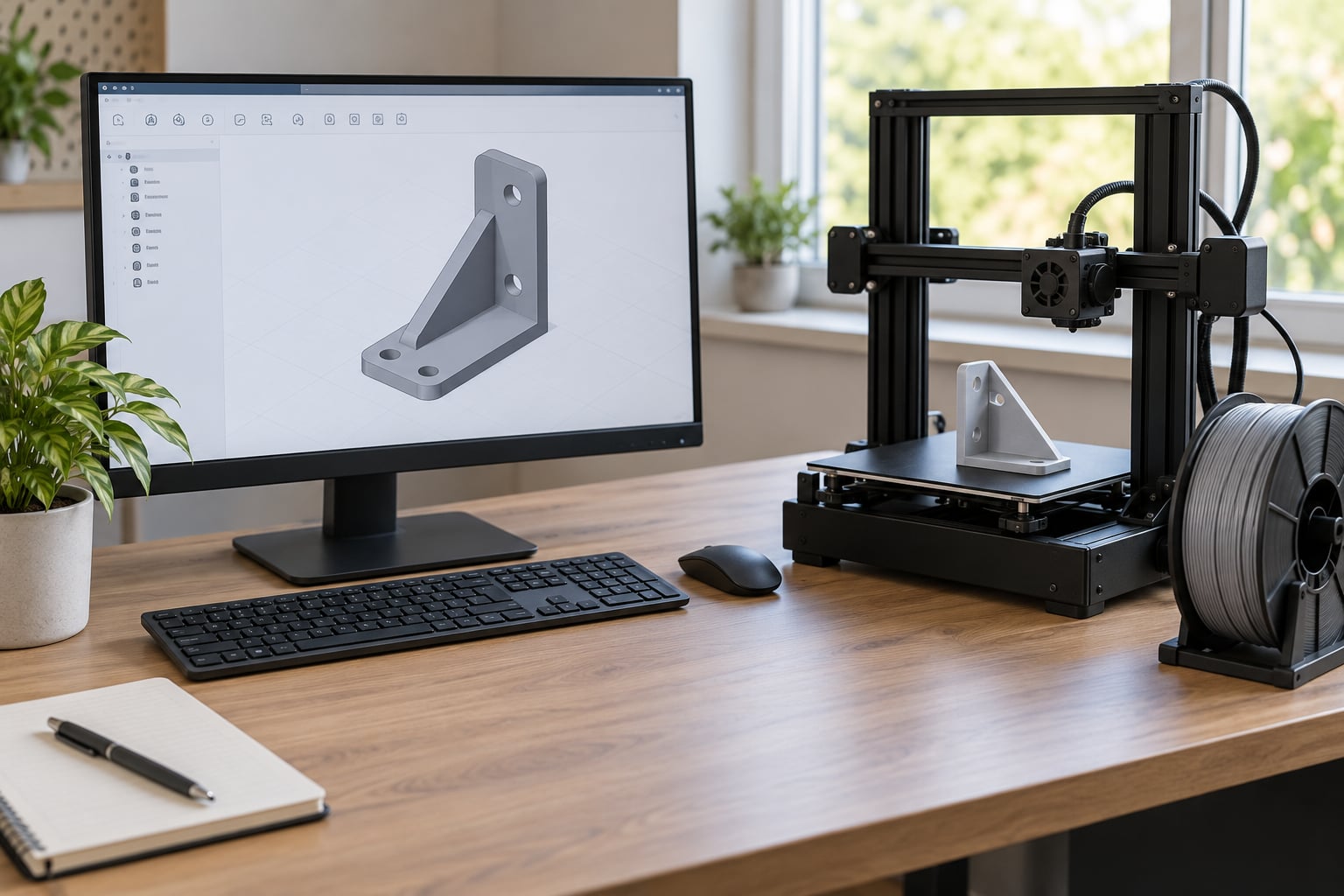
Designing parts for 3D printing in Fusion 360 means modelling with the printer’s limits built in, so the file leaves Fusion already printable: a 1.2 mm minimum wall on a 0.4 mm nozzle, overhangs angled past 45 degrees, holes given real clearance, and chamfers instead of flat shelves that need scaffolding. Get those decisions into the sketch and the part comes off the bed on the first or second attempt instead of the tenth.
This guide walks the whole path, from setting up Fusion for additive work through to exporting a mesh and checking it in your slicer. Every number below is a floor you can tune after a test print, not a law of nature.
Table of Contents
- 1What You Need
- 2How to Design Parts for 3D Printing in Fusion 360 — Step-by-Step
- 31. Set the Print Process and Design Constraints
- 42. Model the Part from a Useful Reference Shape
- 53. Add Walls, Holes, and Rounded Features
- 64. Design Ribs, Braces, and Load-Bearing Areas
- 75. Control Overhangs and Unsupported Geometry
- 86. Apply Printability Tolerances
- 97. Check the Model Before Exporting
- 108. Export the Model for Your Slicer
- 11Common Mistakes
- 12Frequently Asked Questions
- 13What is the minimum wall thickness for 3D printing in Fusion 360?
- 14Why won’t my hole fit the bolt when the Fusion 360 numbers look right?
- 15Should I export STL or 3MF from Fusion 360?
- 16Do I need support structures for my 3D print?
- 17Is Fusion 360 free for personal and hobby use?
- 18Is anything illegal to 3D print?
- 19Conclusion
What You Need
You need four things, and only one of them is the software.
- A Fusion 360 account. Autodesk offers a free personal-use licence for hobbyists and students, which covers designing parts for your own printer. Commercial use needs a paid licence.
- A printer and material in mind. Not just the printer model, the material too. A PLA phone stand and a Nylon gearbox bracket have different thickness rules because of heat and layer bonding.
- Basic CAD skills. Sketching, constraining, extruding, filleting. If you can sketch a rectangle with equal constraints, you can finish this workflow.
- Slicer software. Cura, PrusaSlicer, Bambu Studio, or whatever your printer ships with. Fusion exports a mesh, and the slicer is where you confirm the mesh is sane before committing filament.
Worth saying up front: Fusion’s ribbon names, panel layouts and the placement of some options change between releases, and the commands here follow the current desktop version on Windows. Menu labels shift between platforms and versions more often than people expect, so if a command is not where this says it is, search the Everything bar at the top of the window by keyword. The modelling logic underneath does not change.
How to Design Parts for 3D Printing in Fusion 360 — Step-by-Step
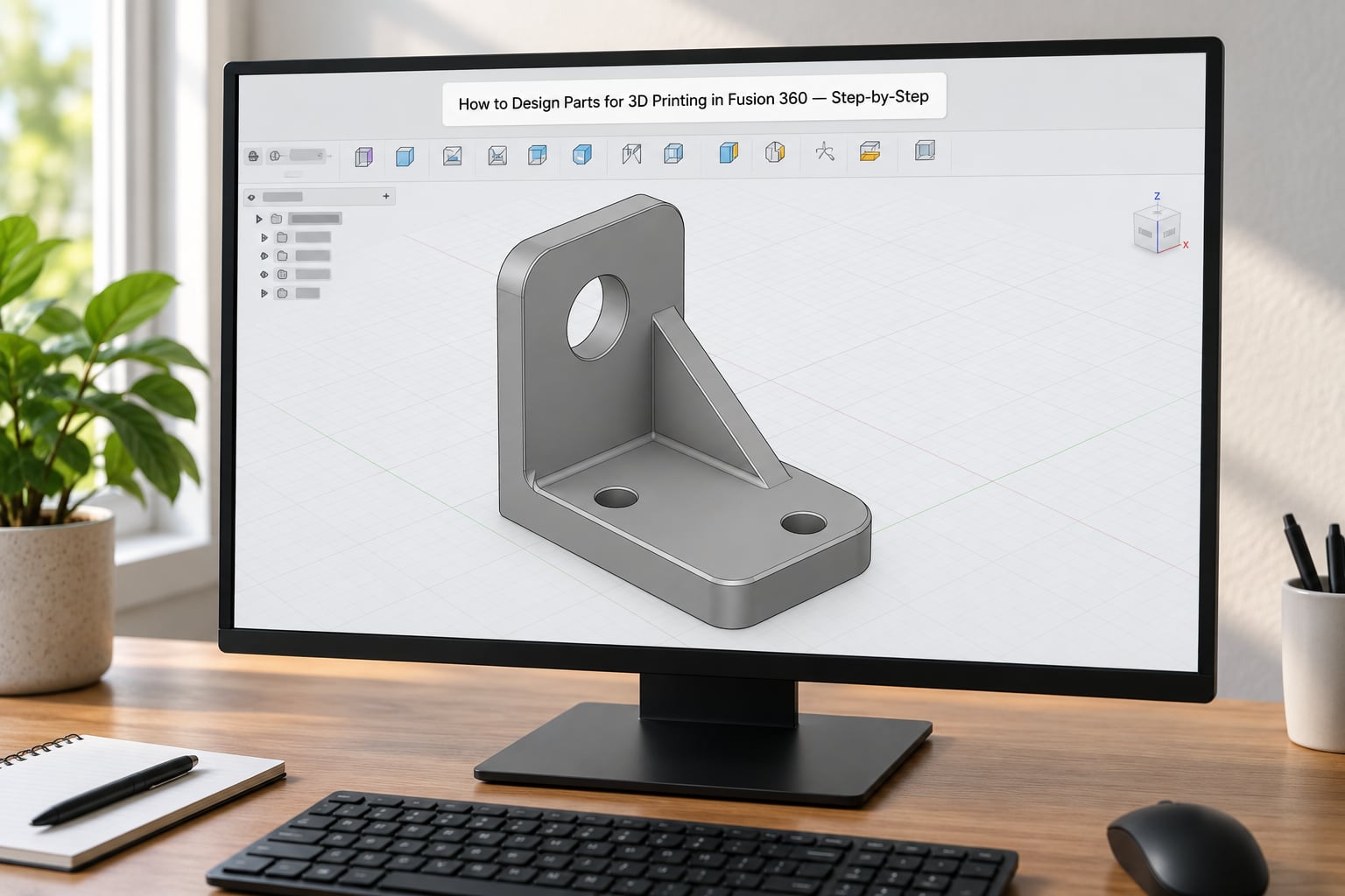
1. Set the Print Process and Design Constraints
Decide your process before you sketch anything, because the process decides every dimension that follows. In Fusion’s preferences, switch the default operation type to Additive so new bodies start oriented Z-up rather than the Y-up default used for machining work.
From there, write down the numbers you will design against. For a typical 0.4 mm nozzle FDM printer: minimum wall 1.2 mm, minimum rib 1.2 mm, overhang limit 45 degrees, minimum hole diameter 2 mm, and a vertical hole coming out roughly 0.2 mm smaller than nominal. Resin printers tolerate thinner walls and much smaller holes, around 0.8 mm and 0.75 mm respectively.
| Feature | FDM (0.4 mm nozzle) | SLA resin | SLS nylon |
|---|---|---|---|
| Minimum wall | 1.2 mm | 0.8 mm | 0.8 mm |
| Minimum rib or gusset | 1.2 mm | 0.8 mm | 1.0 mm |
| Minimum hole diameter | 2 mm | 0.75 mm | 1.5 mm |
| Support-free overhang | 45 degrees | Any angle | Any angle |
| Unreliable long bridge | Above 50 mm | Not applicable | Not applicable |
Treat this table as starting points. A well-tuned machine with a 0.6 mm nozzle handles thicker walls better than the numbers suggest, and a badly tuned one struggles at 1.2 mm.
2. Model the Part from a Useful Reference Shape
Start with a sketch on the base plane and build up. The important habit is constraining rather than eyeballing: place geometry, then add dimensional constraints and fix relations so the profile can never drift. A sketch held together by naked dimensions without relations will move the first time you change a number.
Useful starting shapes include rectangles for plates, circles for bosses, and polylines for brackets. Sketch the silhouette of what the part does, extrude it to full height, then refine.
If the part has to fit around something that already exists, model that object first as its own component and design against it. Experienced makers on r/Fusion360 and 3dprinting.stackexchange consistently describe this as the reliable way to fit a printed part to real hardware rather than to a datasheet. You can measure a physical object with calipers or trace it, then import it as a mesh and use it as a reference body.
3. Add Walls, Holes, and Rounded Features
Walls are the first thing to get right. A 1.2 mm wall on a 0.4 mm nozzle prints as three clean perimeters with no gaps; anything thinner can drop a perimeter and leave a hole in your part. Bosses around holes want the same 1.2 mm minimum, and you get far better results with a counterbore or countersink than with a plain drilled look.
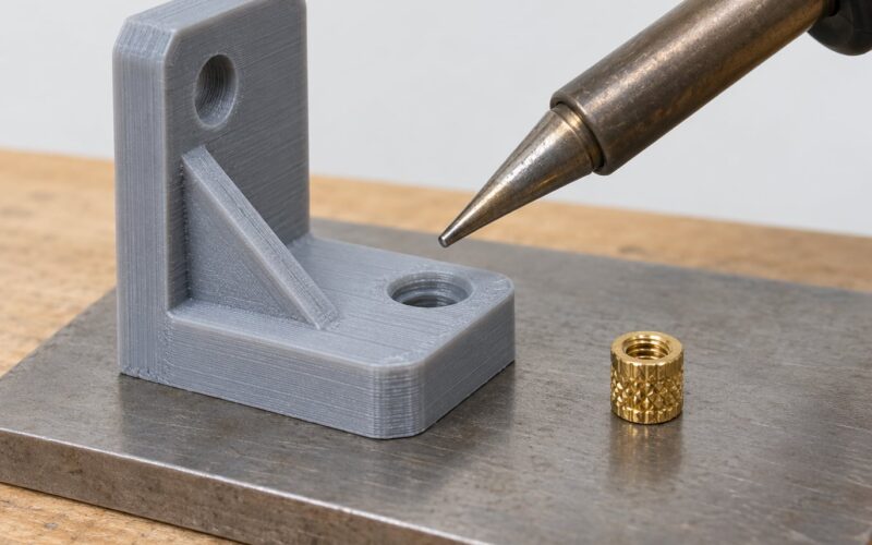
Holes need deliberate sizing. FDM holes come out undersized because the inner perimeter of the hole path is pushed outward by extrusion width, so a 3 mm hole typically measures 2.8 mm. For an M3 bolt, design 3.2 to 3.4 mm for a free-turning clearance fit. Vertical holes need more allowance than holes printed lying down, because the elephant-foot effect widens the bottom of the hole.
Round everything you can. A sharp internal corner is a stress riser and it collects a visible seam artefact where the perimeter turns. A 1 to 2 mm fillet spreads the load and removes the artefact. The same fillet radius is also what keeps a nut trap from tearing the surrounding wall.
Teardrop holes solve a specific problem. A vertical hole through a flat plate needs no support because the material around it is continuous, but a small hole drilled down through a curved or shallow surface often needs a support tower right underneath. Flaring the top of the hole into a teardrop shape removes the need. The Hole tool has a teardrop option under head clearance, or you can sketch a circle with a teardrop profile and cut it manually.
4. Design Ribs, Braces, and Load-Bearing Areas
A 6 mm solid block weighs far more than a 1.2 mm rib and bends almost as well, so ribs are the standard way to stiffen a printed part. The workflow is straightforward: sketch the rib profile on a face, extrude it to the height you need, then use Thicken or a second extrude if you need a symmetric rib in both directions.
Keep rib thickness at or above your minimum wall, and set the fillet where the rib meets the main body. Without that fillet you get a thin, weak fillet-like sliver right at the intersection, and that sliver is where the part cracks under repeated loading.
For a bracket carrying a real load, think about where the load enters and where it leaves. Put material along that path, not in a uniform slab. Gussets at inside corners do the same job in two dimensions, and a fillet at the gusset tip prevents the crack that would otherwise start there.
Printed parts are weakest across layer lines, not along them, because layer bonding is weaker than the material within a layer. A tall thin wall standing on its base fails by snapping at the base. Orienting the part so the load runs parallel to the layers, or adding ribs that break up the stress, is the design answer to that weakness.
5. Control Overhangs and Unsupported Geometry
An FDM printer cannot build in mid-air past roughly 45 degrees from vertical. Every horizontal downward-facing surface past that angle either droops into a mess or needs scaffolding underneath it. Both outcomes cost you surface finish, and support removal on a small feature can break the feature itself.
The fix is usually a chamfer. Where you have a 90 degree overhang, put a 45 degree chamfer on the lower edge and the material prints itself. That is the single highest-value habit in this entire workflow, and experienced users on design forums push it harder than anything else on this list.
For geometry you cannot chamfer, self-support it instead. A 45 degree cone needs no support. A dome blends from vertical to horizontal. Overhangs that sit directly over solid material can bridge short distances without trouble, up to roughly 50 mm on a well-tuned FDM machine. Ribs printed as thin walls at a slight angle are far stronger than supported ones.
Orientation is part of this. A part has a different set of overhangs depending on how you lay it on the bed, and rotating 90 degrees can turn a support-heavy part into a support-free one. Think about it before you model rather than after.
6. Apply Printability Tolerances
Nominal CAD dimensions and printed results rarely agree, so you design a clearance on purpose and then adjust it after a test print. The causes are predictable: material shrinkage, extrusion width pushing hole edges inward, elephant-foot widening the bottom of vertical holes, warping on larger parts, and resin expansion on printed parts.
| Fit type | Clearance per side | Typical use |
|---|---|---|
| Clearance fit | 0.2 to 0.4 mm | Bolt holes, shafts, parts that must assemble without force |
| Sliding fit | 0.1 to 0.2 mm | Pins and dowels, lids and spigots |
| Press fit | -0.1 to -0.2 mm | Snap-in parts, permanent press joints |
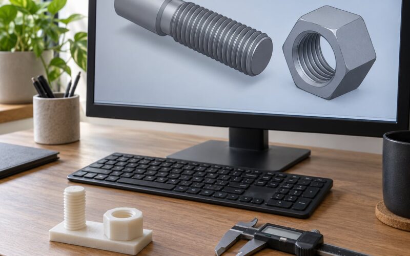
Threads deserve their own rule. Printed threads are soft and wear quickly, so use a thread only where a light-duty fix is acceptable. Give a nut trap extra clearance, about 0.4 mm on an M3, or the nut will not start by hand.
Snap fits work if you shape them well. A cantilever snap arm on a 30 to 40 degree upward ramp deflects during assembly and springs back. Add a small lead-in chamfer at the tip, keep the arm at least 1.2 mm thick, and give it room to flex rather than butting it against a wall.
Drive all of these values from user parameters rather than typing them into each feature. Go to Modify, then Change Parameters, create entries such as m3_clearance or min_wall, and reference them in your sketches with expressions. Change one number and the entire model updates, which turns tolerance tuning into a single edit instead of a hunt through twenty sketches. This is the workflow difference between a CAD model and a printed part.
7. Check the Model Before Exporting
Open a section view and walk through the part looking for things the printer cannot do. Use Measure on the sketch to confirm wall thicknesses rather than trusting the eye. Look for thin walls, open edges, self-intersections and zero-volume slivers, all of which produce a mesh the slicer either repairs silently or chokes on.
Confirm the browser shows one solid body under one component. A design with several bodies in one component exports as a single mesh, which is where a lot of slicer frustration starts, because you then have to split it apart by hand. If you want multiple pieces on one plate, split them into separate components first.
Finally, rotate the model and look at it from the direction it will sit on the build plate. Any surface facing downward and roughly horizontal is a support candidate. Decide now whether to chamfer it, reorient the part, or accept the support.
8. Export the Model for Your Slicer
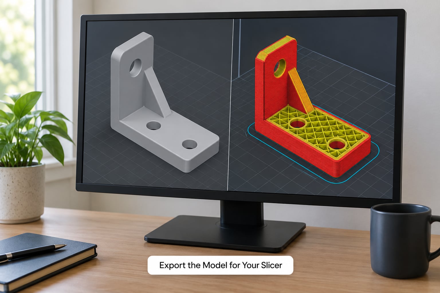
Fusion exports a mesh, not a solid body. The command is Save As Mesh, and the destination type is STL or 3MF. You can also go straight from the browser with Tools, Make, then 3D Print, which opens the 3D Print utility and lets you send the model onward to a slicer without an STL round trip.
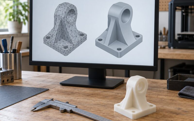
Tessellation is where new users go wrong. Every STL is a triangle approximation of your smooth surfaces, and the quality setting controls how close the triangles sit to the real surface. Maximum quality is not the answer. It produces enormous files with millions of triangles that slow the slicer down without changing the printed result.
| Setting | Typical use | What you get |
|---|---|---|
| Low | Large functional parts, rough surfaces | Small files, visible faceting on curves |
| Medium | Most FDM parts | Balanced file size and curve fidelity |
| High | Resin prints, cosmetic surfaces, small holes | Big files, accurate small features |
Medium is right for most FDM work. Check the surface deviation refinement option so curved surfaces get extra refinement where they need it, and save as binary STL rather than ASCII, which roughly halves the file size with no loss of detail.
| Aspect | STL | 3MF |
|---|---|---|
| Geometry | Triangle mesh only | Triangle mesh plus full colour and material data |
| Colour per body | Lost | Preserved through export |
| Units | Unitless, prone to scaling mistakes | Carries units |
| Support | Every slicer accepts it | Broad slicer support |
| Best for | Single-material prints, service bureaus | Multi-body and multi-colour prints |
If your design has several parts in different colours, this table is the reason to use 3MF. Group the bodies in the browser before exporting and the colour grouping survives into the slicer. The most common repeated question on r/Fusion360 is exactly this: people export a multi-part design as one solid, then resort to Split to Parts and manual per-part recolouring. Grouping bodies and exporting 3MF removes that step entirely.
Import the mesh into your slicer and confirm three things before you print. The part is the size you designed, so check the bounding box against your intended millimetres. The orientation in the preview matches what you intended. And there are no hollow shells or missing faces where the mesh self-intersected. On a multi-body 3MF, assign each body its filament and confirm the colours landed on the right parts.
Common Mistakes
Designing horizontal downward faces. A flat underside wider than the part will droop or need supports. Chamfer the lower edge at 45 degrees and let the printer build it unsupported.
Using nominal CAD dimensions. A hole modelled at exactly 3.0 mm prints at roughly 2.8 mm on FDM. Add clearance in the model through user parameters, then test print and adjust.
Walls below the nozzle’s reach. Anything under three extrusion widths risks a dropped perimeter. Keep walls at three times nozzle diameter as your floor.
Adding supports you do not need. Support towers leave marks and are awkward to remove on small parts. Reorient the part first, then chamfer, and only then reach for supports.
Ignoring orientation until the slicer is open. Rotate the model in Fusion before export. Layer direction changes both overhangs and the direction the part is weakest in.
Tiny holes and internal threads. Sub-2 mm holes print as blobs, and printed threads strip easily. Oversize the hole and use a nut trap with extra clearance instead.
Exporting without inspecting the mesh. Load the file into the slicer and check scale, orientation and shell integrity. Catching a self-intersection there costs a minute; catching it after a failed print costs a plate of filament and an afternoon.
Frequently Asked Questions
What is the minimum wall thickness for 3D printing in Fusion 360?
For a 0.4 mm nozzle FDM printer, 1.2 mm is the practical minimum wall, which equals three extrusion widths and prints as three clean perimeters. Resin printers manage about 0.8 mm. Set your minimum once as a user parameter under Modify, Change Parameters, then reference it in every sketch so changing nozzle size updates the whole model at once.
Why won’t my hole fit the bolt when the Fusion 360 numbers look right?
Because FDM holes print undersized. The inner perimeter of the hole path is pushed outward by extrusion width, so a 3 mm hole typically measures 2.8 mm on the plate, and the elephant-foot effect widens the bottom further. Design 3.2 to 3.4 mm for an M3 clearance fit, then check with calipers and tune the value through a user parameter.
Should I export STL or 3MF from Fusion 360?
STL for single-material parts and for print service bureaus, which is what almost all of them request. 3MF when you have several bodies that need different colours or filaments, because it preserves per-body grouping and colour through export instead of flattening everything into one mesh. STL is a bare triangle file with no units and no material data.
Do I need support structures for my 3D print?
Most FDM parts can be designed support-free. Keep downward-facing surfaces past about 45 degrees chamfered or self-supporting, orient the part so the least material faces down, and make sure any hole through a flat face has continuous material around it. If supports are still needed, keep them small and set a reasonable Z-distance in the slicer.
Is Fusion 360 free for personal and hobby use?
Yes, Autodesk offers a free personal-use licence covering hobbyist and student work, including designing parts for your own printer. Using Fusion 360 to produce parts for money, or in a business where the output is sold or supplied commercially, requires a paid commercial licence. The distinction is about what you do with the output, not whether you are printing at home.
Is anything illegal to 3D print?
Most everyday parts are fine, but rules differ by country and several categories are restricted or tightly controlled, including firearms and firearm components in the United States, and items protected by trademark or copyright that you have no right to reproduce. Exporting certain designs for commercial use can also breach their licences. When it matters, check your local regulations and the design’s terms before printing or selling.
Conclusion
Start by writing down your printer, nozzle and material, then set the design constraints before you open a sketch. Build the part with a constrained sketch, extrude, fillet and chamfer, drive your clearances from user parameters, inspect the body, export at Medium tessellation, and confirm scale and orientation in the slicer before the first layer goes down.
The models that print first time are the ones where printability was decided early rather than patched afterwards. How to design parts for 3D printing in Fusion 360 is less about mastering every command and more about knowing which limits your machine has, and letting a single measured test print tune the numbers for everything after it.