Rotate the model so the force it has to carry runs inside the X-Y plane, along the layers, and never straight across them. FDM prints are far stronger in-plane than through the thickness, and the Z bond between layers runs roughly 30-50% below in-layer tensile strength for PLA, so an orientation that puts the load through Z will crack on the first real pull. Working out the best orientation for print strength takes about ten minutes of planning and one test coupon.
It is not a single answer, though. Orientation is a compromise between the load path, overhangs, footprint, surface finish and print time, and almost no part gets all five for free. What follows is the process I use to decide, how to check the decision in your slicer, and how to test it.
Table of Contents
- 1What You Need to Find the Best Orientation for Print Strength
- 2Step-by-Step: Comparing Orientations and Locking One In
- 3Step 1: Identify the Part’s Main Load Paths
- 4Step 2: Understand Which Print Direction Is Strongest
- 5Step 3: Generate and Compare Candidate Orientations for Print Strength
- 6Step 4: Optimize Settings for the Chosen Orientation
- 7Step 5: Test and Validate the Result
- 8Common Mistakes While Comparing Orientations
- 9Common Mistakes and How to Fix Them
- 10Frequently Asked Questions
- 11What is the strongest orientation for FDM printing?
- 12Is 100% infill stronger than lower infill percentages?
- 13Should a functional part be printed vertically or horizontally?
- 14How do I choose an orientation for a hole, hook, or bracket?
- 15Does layer height change the best print orientation?
- 16Are orientation test results different for resin, SLS, and metal AM?
What You Need to Find the Best Orientation for Print Strength
Before you touch the rotate gizmo, gather these five things. Without them the comparison is guesswork.
- The printer and its build volume. Orientation decides whether the part fits at all, so check the diagonal footprint and height against your machine before you get attached to a layout.
- The slicer. Cura, PrusaSlicer and Bambu Studio all let you try several placements quickly and flip between them.
- The filament, dry. Wet PLA and PETG print weak in every direction. Dry filament before you blame the orientation for a failure.
- The model itself. Know which face is the mounting face, where the bolts go, and which direction the part hangs in service.
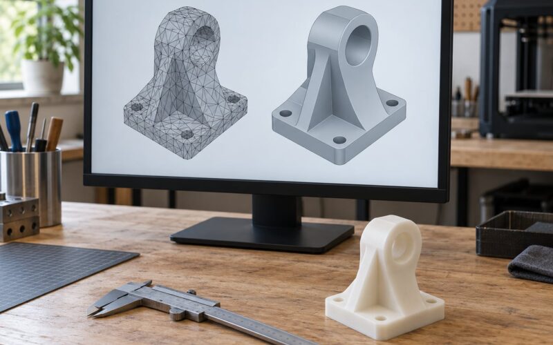
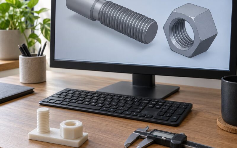
- A caliper or steel rule, plus a small test coupon model. Dimensional checks across the part catch orientation problems that strength tests alone will miss.
Add somewhere safe for a destructive pull test. A printed coupon that snaps under a desk hinge or a clamped two-by-four is fine; a printed bracket carrying a person is not a test rig.
Step-by-Step: Comparing Orientations and Locking One In
Step 1: Identify the Part’s Main Load Paths
Orientation decisions come down to one question: which direction does the force travel through the part? Name the main load first, then orient for it.
Tension is a pull along the length of the material, like a hook taking weight. Compression is a push, like a shelf pressing down on a column. Bending is a lever, where the surface furthest from neutral axis carries the most tension and compression. Impact is sudden and it spreads out. Torque is twist. Shear is a sideways slide past a joint, and it is the failure mode FDM parts are worst at because it runs straight along the layer bond.
One part can carry several at once. A shelf bracket bends and also shears at the wall fixings, so bend first, then check whether the fixing region adds a shear path you have to dodge. Usually there are two or three loads that matter and a dozen features that only look important.
A quick check helps: in the CAD viewer, look at the part from the side the force comes from. Whatever surface the load pushes or pulls on is the surface that wants to be parallel to the build plate.
Step 2: Understand Which Print Direction Is Strongest
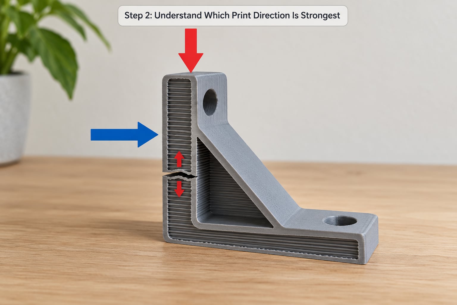
Within a layer, the extruded beads fuse side by side into a mass close to the strength of the raw filament. Between layers, the bond depends only on heat from the fresh bead re-melting the layer underneath it. That interface keeps micro-voids and sits measurably below in-plane strength, which is the whole reason layer lines show up as cracks.
The published figures vary by material, printer and test method, so treat them as a range rather than a constant. The commonly cited figure for PLA is 30-50% lower tensile strength along Z than within the X-Y plane. Filled and engineering filaments fare better because the fibres bridge the interface, and photopolymer resin is close to isotropic because curing forms chemical bonds rather than a thermal weld.
Two things shift the gap. Geometry matters: a tall thin column standing on end has almost no cross-sectional area in XY, so it is weak no matter which axis you call strong. Layer height matters too, because a thicker bead reheats more of the layer below and fuses it more completely.
Step 3: Generate and Compare Candidate Orientations for Print Strength
Make three or four placements, not one. In every current slicer the flow is the same: rotate the model with the gizmo or the rotate field in the settings panel, then drop it to the bed with the auto-drop tool, then look at the preview. Most slicers also have a plate-search function that tries several angles and scores them for overhangs, height and material.
For each candidate, check four things before you fall in love with one:
- Overhangs. Anything past roughly 45 degrees from vertical starts needing support, and support adds surface marks and time.
- Support contact. Where a support touches a face, the slicer inserts a small Z-gap so the part can be removed. That interface is weak, so keep it away from the load path.
- Footprint and stability. A tall thin orientation can topple mid-print, which wastes the whole plate.
- Layer count. Lay a long part along its longest dimension and the layer count, print time and material all drop sharply. A cylinder stood upright can need roughly three times the layers of the same cylinder lying down.
Watch for the trap here: an orientation that puts the load through Z no matter how good it looks in preview. Open the slice view, pick a layer through the loaded area, and check that the load runs along the extrusion path rather than across the layer gap. That single check catches most mistakes.
When no layout puts every load in-plane, tilt it about 45 degrees. You split the weakness between two axes instead of dumping all of it into Z, which is often the difference between a part that survives and one that does not.
Step 4: Optimize Settings for the Chosen Orientation
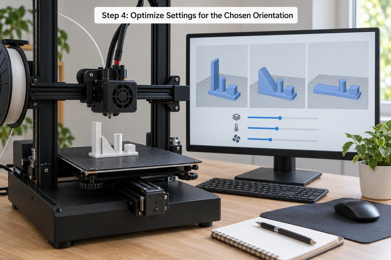
Orientation sets the ceiling; settings decide how close you get to it. Work through these in order of impact.
Nozzle temperature first. Printing PLA at 215-220°C rather than 200°C narrows the Z gap by roughly 10-15% with no geometry change. It costs stringing and a slightly rougher surface, and for some printers it costs a failed print from ooze. Check that your filament’s own temperature range covers it.
Walls before infill. Walls run around the perimeter of every layer and take load at the surface, where stress concentrates. Infill sits inside and mostly stops voids and adds stiffness. Raising infill on a part with a bad load path does very little, which is why parts fail along layer lines despite 60% infill and five walls. Add perimeters before you add infill.
Top and bottom layers. More of them helps compression and impact, and barely touches the Z bond in the middle of the part.
Layer height. Thicker layers give the bead more thermal mass to re-melt the layer below, which helps interlayer bonding and cuts print time. Thinner layers sharpen detail and small features. Do not go thicker than about three quarters of your nozzle diameter.
Cooling. Part cooling improves overhangs and bridges but steals heat from the bond. On a functional part with few overhangs, cut fan speed or use a minimum layer time instead.
Print speed. Slower speeds mean more time between the hot bead and the layer below. Beyond a point it wastes time and can worsen stringing.
Bed adhesion. Orientation affects warping directly. Large flat faces on the plate help, and so does a brim or raft on materials that move. Warp is a dimensional and cosmetic problem more than a strength one, but a part that comes off the plate bowed rarely fits afterwards.
No single profile is right for everything, and copying one from a forum without matching layer height and cooling will not reproduce the result. Change one setting at a time and write down what you changed.
Step 5: Test and Validate the Result
Coupon testing is the only way to know what your printer and filament actually do, and it costs a few grams of plastic. Print a simple beam, roughly 80 mm long and 10 mm by 10 mm in section, three times: one flat on its widest face, one on edge, one standing on its 10 mm by 10 mm end.
Then break them under the same three-point bend and note the load at failure or just record which one survives longest. The flat coupon should win, and the standing coupon should be clearly last. If the flat one loses, something in your setup is off: usually wet filament, a clogged nozzle, or a first layer that never gripped.
Two extra checks on the real part before you trust it. Measure the key dimensions against the model, because a load-bearing hole that moved will change how the bolt loads the part. And inspect the layer interface on a broken scrap; if it separates cleanly at a line, the orientation is still wrong no matter what the numbers said.
Common Mistakes While Comparing Orientations
Maximising infill without matching the load path is the most common one, and it is expensive. Assumption number two is treating all directions as equally strong, which is false for every material and most obvious in PLA. Holes and sharp notches placed badly are third: a hole whose axis runs along Z splits along that axis when a bolt loads it, so orient holes so their axis lies in the X-Y plane where possible. Finally, comparing prints made with different settings tells you nothing except that the settings differed.
Common Mistakes and How to Fix Them
A part snaps cleanly along a layer line under load. The load is crossing the layer bond. Rotate so the loaded surface lies flat, and raise nozzle temperature within the filament’s range to widen the bond.
It looks correct but is still weak. Support contact landed in the loaded area, and the slicer’s Z-gap sits right in the load path. Re-orient to move the support scar away, or hand-cut a hole and thread it afterwards.
The strong orientation topples mid-print. The footprint is too small for the height. Add a brim, drop the part to a lower angle, or split the job into two shorter prints.
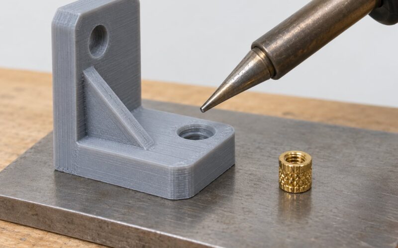
Threads strip or crack. Orient the hole axis along X or Y, print it at 70-80% of full diameter, and add a short perpendicular wall behind the boss to stop it splitting out along Z. Threaded bosses should be solid, not hollow, since the threads themselves carry the load.
The part fits on the first print, then fails in service. Orientation was chosen for fit, not strength, and a week of load found the weak interface. Go back to Step 1 and name the real load.
A service bureau printed it your way and it broke anyway. It reoriented the file for bed adhesion and did not tell you. Put the required orientation in the order as a note alongside the file, or upload a pre-oriented mesh so there is nothing left to change.
For everyday parts and jigs, start from the load path and accept the visual result. For functional prototypes, test a coupon in the same material first and add a printed-in safety margin. For anything safety-critical, stay away from FDM for the loaded element and use a process and material qualified for the job.
Frequently Asked Questions
What is the strongest orientation for FDM printing?
Laying the part flat on the build plate is strongest for most geometry, because the largest surface area sits parallel to the layers and loads travel in-plane. Standing it on end maximises Z loading, which is the weakest direction, usually 30-50% below in-plane strength for PLA. The exception is tall thin columns, where cross-sectional area matters more than axis.
Is 100% infill stronger than lower infill percentages?
Only marginally, and far less than orientation changes. Infill fills the interior, while walls carry load at the surface where stress concentrates. If a part fails along layer lines, raising infill will not fix it, because the failure is in the bond between layers rather than in the core. Add perimeters first, then reorient, then revisit infill.
Should a functional part be printed vertically or horizontally?
Horizontally, so the main load runs inside the X-Y plane along the layers. Vertical printing helps only when it reduces layer count, improves accuracy on a tall feature, or keeps overhangs off a cosmetic face. If no layout puts every load in-plane, tilt the part about 45 degrees to split the weakness between two axes instead of stacking it all in Z.
How do I choose an orientation for a hole, hook, or bracket?
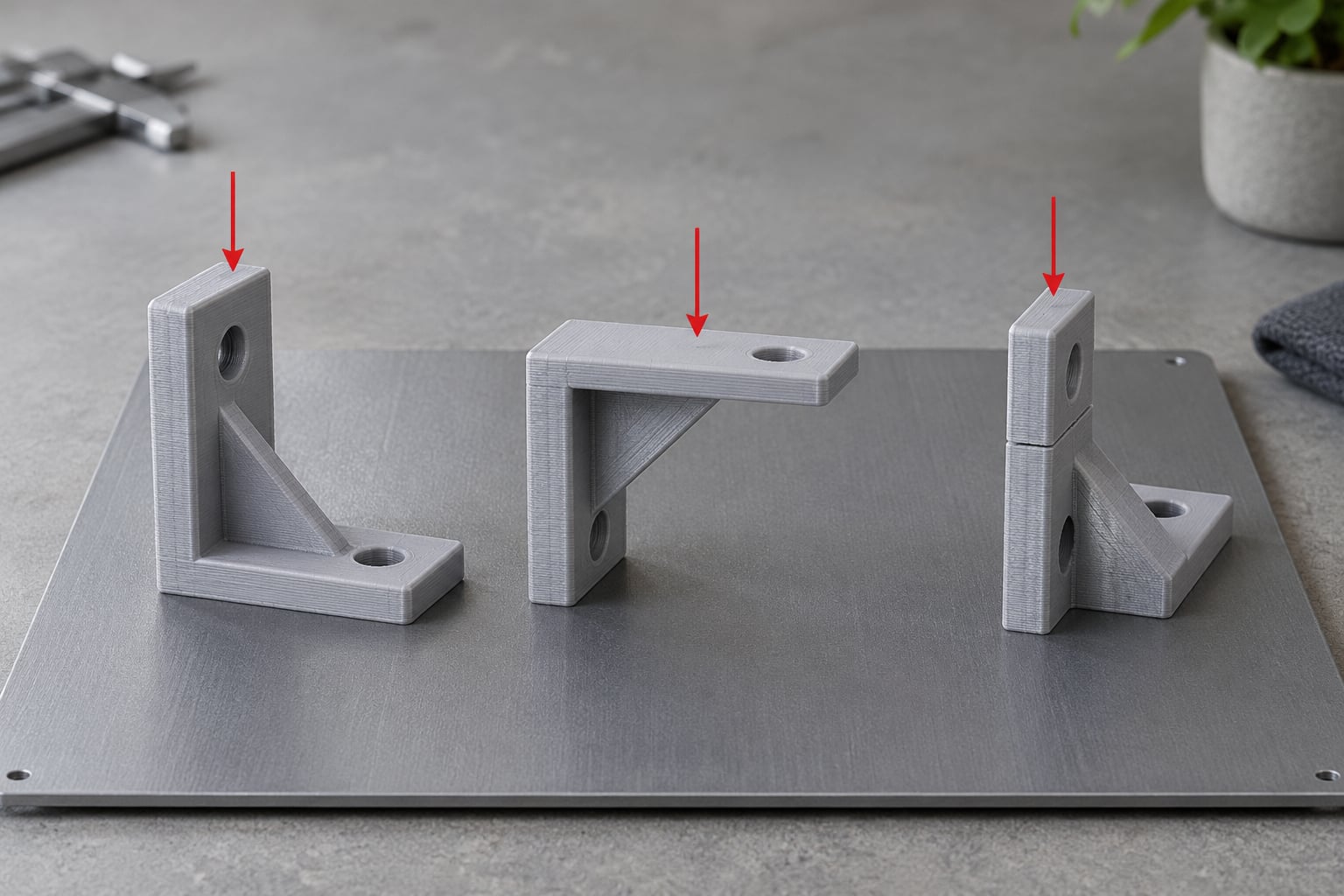
For a hole, orient its axis along X or Y so bolt loads do not split it along a layer line, print it undersized, and back it with a perpendicular wall. For a hook, put the curved surface flat so the pull runs in-plane. For a bracket, lay the mounting face down and make the section between the fixings as deep as the plate allows.
Does layer height change the best print orientation?
Not the best choice, but it changes the gap you are trying to close. A thicker bead carries more heat into the layer below and fuses it more completely, so a taller part gains a little relative strength at 0.28 mm compared with 0.12 mm. Thinner layers suit small features and fine detail instead. Stay at or below about three quarters of your nozzle diameter.
Are orientation test results different for resin, SLS, and metal AM?
Yes, and the gap narrows as the process changes. Resin prints are close to isotropic because curing forms chemical bonds between layers, so orientation matters far more for surface finish and supports. SLS parts are also nearly isotropic, since sintering bonds the whole layer at once. Fibre-reinforced composites go the other way, with the fibres laying in the X-Y plane and making orientation matter again.
Start with the load. Look at the part from the side the force arrives from, lay the loaded surface flat on the plate, and check the slice view before you slice it. That single orientation pass solves more failures than any infill or wall setting, and it costs nothing. Last reviewed for 2026, and the coupon test is still the fastest way to check the claim on your own printer.