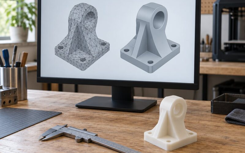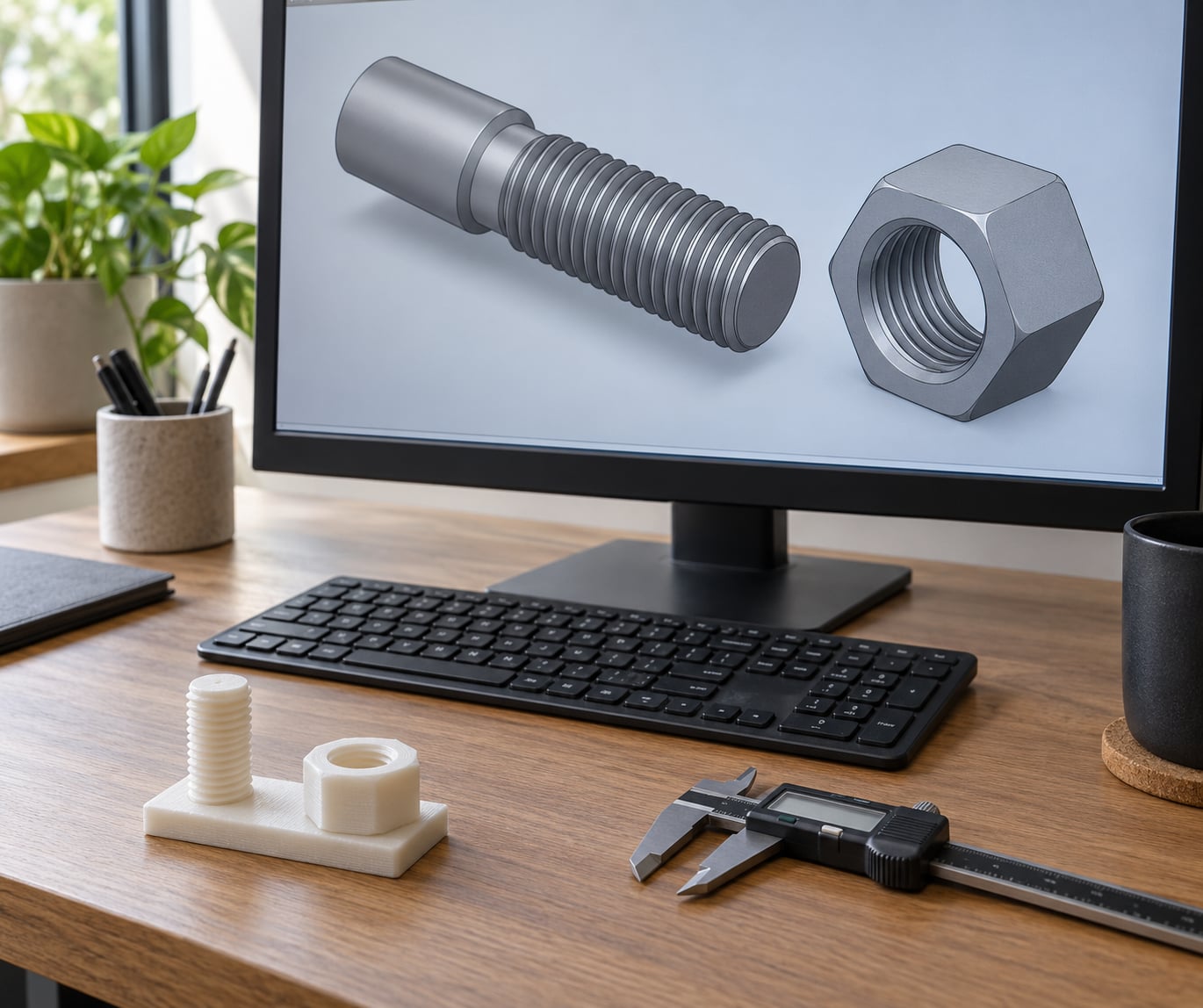
The short answer: model the thread as real helical geometry, not as a cosmetic annotation, then add about 0.15 to 0.30 mm of clearance so the printed parts actually mate. A CAD thread drawn at nominal size is dimensioned for a CNC machine accurate to roughly 0.001 mm, while a consumer FDM printer wanders by 0.1 to 0.3 mm, so a mathematically perfect thread comes out of the nozzle jammed and unassemblable. Getting it right takes maybe an hour for the model plus one small test print, and almost all of that time is spent on the tolerance, not the helix.
The sequence below is the one I use: choose a standard profile, size the joint, set clearance, model the external thread, model the internal thread, add lead-ins, orient the part, then print a coupon before committing to the full part.
Table of Contents
- 1What You Need
- 2Step-by-Step: How to Design Threads for 3D Printed Parts
- 3Define the thread standard and joint requirements
- 4Set the clearance and modeling tolerances
- 5Model the external thread
- 6Model the internal thread
- 7Add a lead-in and thread termination
- 8Design for printing orientation and support
- 9Export, print, and test the fit
- 10Common Mistakes
- 11Quick design tips for stronger printable threads
- 12Frequently Asked Questions
- 13What is the best thread clearance for FDM 3D printing?
- 14Should I use real ISO threads or a simplified 3D-printing thread?
- 15Can you 3D print internal threads reliably?
- 16How do I make printed threads stronger?
- 17What thread direction should I use for FDM and resin printing?
- 18Do resin printers need different thread tolerances than FDM printers?
- 19Conclusion
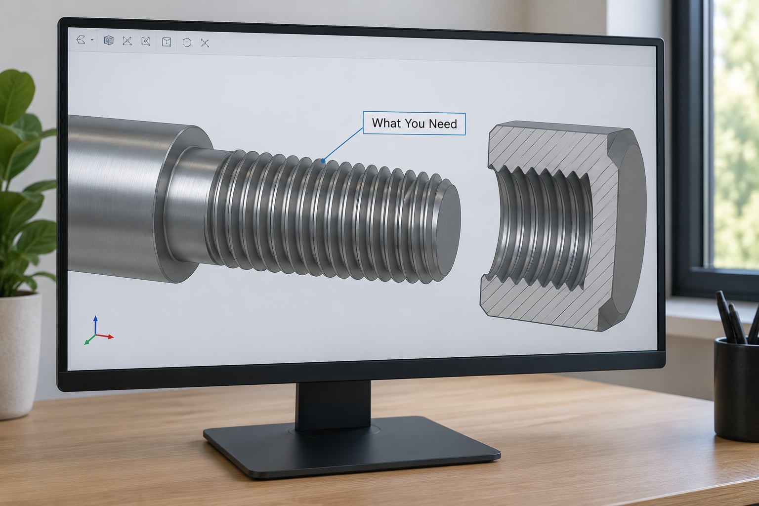
What You Need
Four things, and none of them expensive. The first is CAD software that can create a swept or helical profile rather than only a cosmetic thread. Fusion 360, SolidWorks, Onshape, Shapr3D and FreeCAD all do this; Tinkercad has no thread tool at all, so threads there come from a community screw generator or a hand-built helical sweep.
The second is the thread standard itself. ISO metric is the default choice for printed joints because the 60 degree profile is forgiving and the sizes line up with hardware store bolts. Know what each term means before you start:
- Pitch — distance from one thread crest to the next, in millimetres.
- Major diameter — the outside diameter of an external thread, the inside diameter of an internal one.
- Minor diameter — the root diameter across the bottom of the thread.
- Crest — the top of the thread. Root — the bottom valley.
- Flank — the sloped side face between crest and root. Thread angle — the included angle, 60 degrees for metric.
- Clearance — the deliberate gap you add. Tolerance — the allowed deviation of a manufactured feature. They are different things, and mixing them up is the source of most bad fits.
Third, you need to know your process. FDM parts shrink, resin parts expand slightly and cure with a different dimensional drift, and a filled filament behaves like neither. Fourth, you need a way to measure: calipers for the coupon, and ideally a printed or purchased thread gauge for the final check.
Step-by-Step: How to Design Threads for 3D Printed Parts
Define the thread standard and joint requirements
Start with what the joint has to do. A printed bolt turning into a printed nut in an adjustable phone stand carries almost no load, so a fine pitch and a short engagement are fine. A lead screw driving a Z axis is a different animal: it wants a coarse pitch, a long engagement and thick surrounding walls.
Pick the designation first — M8 x 1.25 means an 8 mm nominal major diameter with 1.25 mm pitch. Coarse pitch beats fine pitch almost every time on a printed part, because a 1.25 mm pitch gives the layer lines and the extrusion width more room to land cleanly than a 0.75 mm pitch does. Threads at or below M12 need noticeably more trial and error, and below M4 the crest becomes fragile enough that I avoid it for anything that gets unscrewed repeatedly.
Set the engagement length before you model anything. Roughly one and a half times the nominal diameter is a sensible minimum for a plastic thread, which on an M8 gives about 12 mm of engagement. Threading all the way through a thin wall wastes filament and gives you nowhere to put a wrench.
Set the clearance and modeling tolerances
This is the step that decides whether the joint works. If the external thread is modelled at true nominal size and the internal thread is also modelled at true nominal size, they share a single surface and will bind the instant they touch. You need a gap on the flanks. The common working range across maker forums is 0.1 to 0.3 mm of total diametral clearance, with 0.15 mm and 0.20 mm cited most often as values that work.
Apply that gap to one part or split it across both. Offsetting only the internal thread keeps the external thread at full nominal size, which is what you want when a real metal bolt has to pass through. Offsetting both halves the error and usually gives the most forgiving fit for printed-to-printed joints.
| Thread size | PLA / PETG printed-to-printed | CF-filled filament (PAHT-CF and similar) | Resin (MSLA) |
|---|---|---|---|
| M3 x 0.5 | 0.20 mm | 0.12 mm | 0.10 mm |
| M4 x 0.7 | 0.20 mm | 0.12 mm | 0.10 mm |
| M5 x 0.8 | 0.18 mm | 0.10 mm | 0.08 mm |
| M6 x 1.0 | 0.20 mm | 0.12 mm | 0.08 mm |
| M8 x 1.25 | 0.20 mm | 0.12 mm | 0.08 mm |
| M10 x 1.5 | 0.25 mm | 0.15 mm | 0.10 mm |
| M12 x 1.75 | 0.30 mm | 0.18 mm | 0.10 mm |
| M16 x 2.0 | 0.30 mm | 0.18 mm | 0.12 mm |
| M20 x 2.5 | 0.35 mm | 0.20 mm | 0.12 mm |
Two reasons the numbers drift upward with size. Bigger parts accumulate more dimensional error over their length, and bigger threads carry more load, so a little more slop is worth the lost precision. Two reasons they drift downward with carbon fibre: filled filaments shrink less and print closer to true size than unfilled ones.
Most CAD packages expose this as a thread tolerance class such as 6g on the external thread and 6H on the internal one, or as an explicit offset face value in the thread dialog. If the tolerance class control feels abstract, type the clearance directly into the offset field and ignore the class naming.
Model the external thread
Two routes work. The first uses the native thread command — Fusion 360’s Thread tool, SolidWorks’ Hole Wizard thread option, Onshape’s Helix and Sweep. The second builds a triangular profile in the sketch, draws a helix, and sweeps the profile along it. The helix route gives you direct control over the profile shape, which some makers prefer because they can blunt the crest deliberately.
Whichever route, three details matter for printability. Truncate the crest slightly rather than leaving a knife edge, because a sharp printed crest is the first thing to shear off. Round it over with a fillet of roughly a quarter of the pitch, the way an injection-moulded plastic thread is designed. And keep the root geometry printable — an internal sharp root is impossible to produce without a sharp internal corner on the nozzle.
Finish the end of the run with a partial thread rather than a full thread that terminates in mid-air on an unsupported overhang. About half a turn of partial thread guides the mating part in without dropping a fragile curl of filament into the gap.
Model the internal thread
The internal thread is the same profile cut into the part, with the same clearance applied. The trap is applying the clearance twice — once through the offset in the thread tool and once by modelling the hole oversize — which silently gives you double the intended gap and a joint with visible slop in every direction.
Make the opening of the hole printable and easy to inspect. A chamfer or countersink at the mouth means the first layer of the hole is not a razor-thin ring hanging in space, and it gives a real metal screw a lead-in that a chamfered metal part would have anyway. Keep at least one full wall thickness of solid material around the thread, and add generous fillets where the thread runout meets the hole wall so the corner does not become a crack starter.
If the internal thread is going to accept a hardware store bolt rather than a printed stud, drill to the ISO tap drill size minus 0.2 to 0.3 mm instead of modelling a thread. That undersize is deliberate: it leaves a small amount of material for a tap to cut and lets you ream the hole by hand if the fit is off.
Add a lead-in and thread termination
A lead-in is a short conical or radiused section at the start of the thread that guides the two parts together instead of asking the crest to find a hole at speed. On an external thread a chamfer at the tip does it. On an internal thread, a countersink does it. Give the lead-in a diameter generous enough that it self-centres — roughly the pitch plus half a millimetre of extra radius works well on most sizes.
Thread termination is the same idea at the far end. A full thread that stops dead leaves a sharp edge on the final crest and can bind the mating part as it bottoms out. A runout over one turn removes that edge. If the thread goes all the way through the part, put the runout on the exit side too.
Design for printing orientation and support
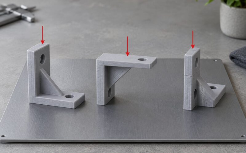
Threads print best when the helix axis sits as close to vertical as the design allows. Printed vertically, each new layer lands on top of a complete, continuous ring of thread material, so the profile stays round and the layer adhesion runs across the whole flank. Printed horizontally, the nozzle lays a small bridge across each thread, and those bridges are the weak points that strip first.
That said, a vertical internal thread can be the harder case. The hole’s roof and the mouth both become overhangs, and the mouth ring is the place a first layer likes to curl. The usual fix is the chamfer from the previous step — it turns the unsupported mouth ring into a supported cone. Anything steeper than about 45 degrees of unsupported overhang needs supports in resin work, and most FDM slicers can bridge it if you slow the outer wall down.
Orientation is not the only slicer lever. Layer height under about 0.16 mm and slower outer-wall speeds both visibly improve thread fidelity, because the thread flank is a small feature that a coarse layer can miss entirely. Wall order matters too: print the perimeters first and the infill last, so the thread flank is a solid wall rather than a sparse grid. And before you redesign the model, try trimming about 0.05 from your flow rate — that loosens a tight printed-to-printed fit without touching the geometry. If that does not fix it, the problem is in the design, not the slicer.
Export, print, and test the fit
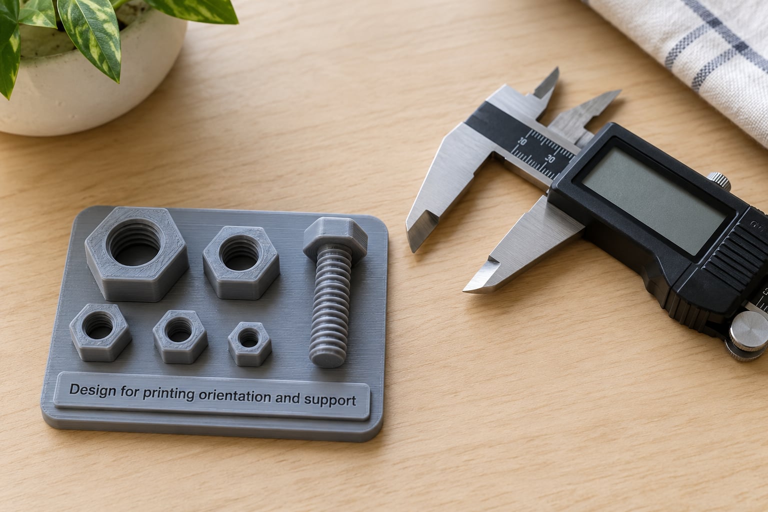
Print one coupon before the real part. Build a small plate carrying three nuts and one bolt at your chosen clearance, three nuts at a clearance 0.1 mm larger, and one larger nut from a hardware store as a reference. Label them by embossing the clearance value on each face so you can tell them apart once they are off the bed.
Run the fit test in a fixed order. Insert the printed bolt into the first nut by hand with no tool. If it will not start, the clearance is too small. If it spins freely with more than a few degrees of backlash, it is too large. Screw it fully in and back it out five times, watching whether the crest of the printed thread rounds off or shears. Then check the metal reference: a printed nut that accepts a real M8 bolt cleanly is usually the most useful result of the whole exercise.
Measure with calipers before you change anything. Comparing the printed major diameter against the nominal tells you whether your machine is running large or small, and that number saves you from guessing on the next design. Once the coupon tells you the right clearance for your printer and material, write it into the model as a parameter and reuse it.
Common Mistakes
Almost every thread problem I get asked about falls into one of six rows, and the cause is nearly always in the model rather than the slicer.
| Symptom | Cause | Fix |
|---|---|---|
| Threads bind and need a vice and wrench to separate | Clearance too small, or none applied; the CAD default offset is far tighter than FDM reality | Raise clearance to 0.20 to 0.30 mm on the internal thread and reprint the coupon |
| Thread starts but bottoms out part way | Diametral error over a long engagement, or the runout was left sharp | Shorten the engagement, add a one-turn runout, or move to a coarser pitch |
| Joint is loose with visible wobble | Double-applied clearance, or XY compensation pushing holes oversize | Check the offset is applied once; correct XY compensation and re-measure |
| Threads strip after a few turns | Sharp crest, no fillet, or thin surrounding wall failing before the thread does | Add a crest fillet, thicken the surrounding wall, switch to PETG or a filled filament |
| Crest flakes or layers separate on the flank | Horizontal thread orientation bridging across the profile | Rotate the part so the axis is near vertical, or slow the outer wall |
| Mouth of the hole tears on the first layers | Unsupported ring at the hole entry | Add a countersink or chamfer and re-slice |
Quick design tips for stronger printable threads
Filleting the crest is the single highest-value habit here, because a printed sharp crest is already rough from the layer lines and a fillet gives the load somewhere to go. Beyond that, keep solid material around the thread generous — a thread in a 1 mm wall is decoration, while the same thread in a 3 mm boss holds real load. Coarser pitch beats finer pitch every time on a printed part. And use PETG or a filled filament over PLA for anything that gets assembled and disassembled repeatedly, since PLA threads go brittle at the crest long before they shear.
Frequently Asked Questions
What is the best thread clearance for FDM 3D printing?
Most makers land between 0.15 mm and 0.30 mm of diametral clearance on a printed-to-printed joint, with 0.20 mm the safest starting point for PLA and PETG. Carbon-filled filaments run tighter, closer to 0.10 to 0.15 mm, because they shrink less. Print a coupon at two or three values and let the test decide rather than trusting a single number.
Should I use real ISO threads or a simplified 3D-printing thread?
Use real ISO metric geometry when a metal bolt, nut or heat-set insert needs to pass through, since the standard profile guarantees an outside part will fit. Use a simplified, blunter profile when both sides are printed and nothing else ever touches the thread, because a rounded crest prints and survives better than a sharp one.
Can you 3D print internal threads reliably?
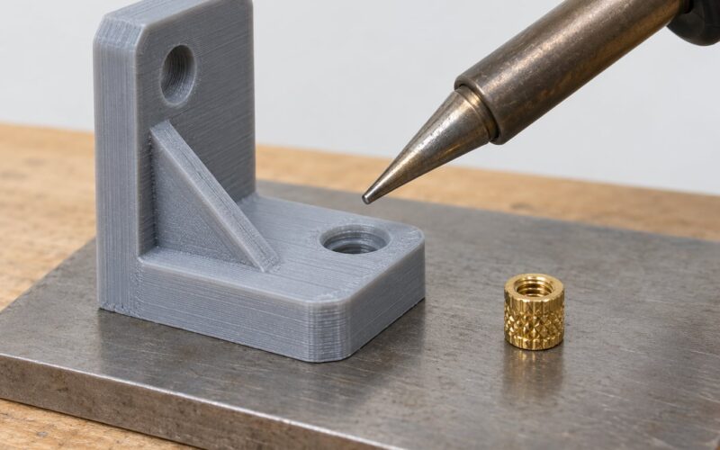
Yes, at coarse pitch and moderate size, provided you give the hole mouth a chamfer or countersink and print with the axis as near vertical as possible. M6 and above works well; below M4 the crests become too fragile to trust. If the joint carries real load, a heat-set brass insert is the more dependable answer.
How do I make printed threads stronger?
Round the crest with a fillet of roughly a quarter of the pitch, thicken the material surrounding the thread, and choose a coarser pitch so each flank has more room. On the print side, drop layer height to 0.16 mm or below, slow the outer wall, and keep infill away from the thread flanks. PETG and filled filaments also hold up far better than PLA.
What thread direction should I use for FDM and resin printing?
Print with the thread axis as close to vertical as the part allows. Each layer then lands on a complete ring of thread material, which keeps the profile round and puts layer adhesion across the whole flank. Horizontal threads rely on bridging and are the first thing to strip. In resin, keep unsupported features at 30 degrees or shallower and rely on a countersink at the hole mouth.
Do resin printers need different thread tolerances than FDM printers?
Yes, resin needs much less clearance. A good MSLA print holds dimensions to within a few hundredths of a millimetre, so 0.08 to 0.12 mm of clearance works on most sizes where FDM wants 0.20 to 0.30 mm. Resin also resolves fine pitch far better, which is why small detailed threads are more practical there.
Conclusion
Start conservative: model a real thread, put 0.20 mm of clearance on it for PLA or PETG, add a chamfer at the entry, and print a small coupon with a couple of variants. Measure the fit, adjust the clearance by 0.05 mm at a time, and once the printed nut takes a real hardware store bolt cleanly, keep that value as a parameter for every thread you design after it. Last updated for 2026.