Tolerances for 3D printed holes and pins are simply the gaps you design into a mating pair so the parts still fit after printing. For FDM, make the hole 0.2 mm larger in diameter than the pin for a snug fit, 0.4 mm larger for a free-sliding fit, and 0.1 mm larger for a press fit — then add a 0.5 mm chamfer to the top of every hole. Two parts modelled to touch at nominal size will almost never fit as printed, because the nozzle lays a bead that swells wider than its programmed path.
The numbers below are starting points for a 0.4 mm nozzle at a 0.2 mm layer height. They shift with material, machine, layer height and how fussy your application is, so the coupon workflow later in this guide is the real answer for anything that matters.
Table of Contents
- 1What Are Tolerances for 3D Printed Holes and Pins?
- 2Tolerances for 3D printed holes and pins versus clearance
- 3Per side or total: how to read a clearance number
- 4Why nominal CAD dimensions are not the finished size
- 5How Do You Specify a Hole-and-Pin Fit?
- 6The fit classes you actually need in printed assemblies
- 7Hole-as-master: put the error on the hole, not the pin
- 8Recommended Starting Clearances by Process and Material
- 9Starting clearance by fit type
- 10Material adjustments on top of the baseline
- 11Tolerance ranges by print process
- 12What Affects 3D Printing Tolerances?
- 13Two reasons printed holes come out smaller
- 14Layer height, nozzle size and the limits of X/Y and Z accuracy
- 15Material shrinkage, cooling and orientation
- 16Calibration, first layer and measurement error
- 17How to Model Holes and Pins for Reliable Fit
- 18Use the hole as the master dimension
- 19Chamfer every hole you plan to insert into
- 20Do not model more precision than you can measure
- 21Choose the axis orientation last, for the fit
- 22How to Test and Adjust a Hole-and-Pin Fit
- 23Build the coupon
- 24Measure and read the result
- 25Common Hole and Pin Fit Problems and Fixes
- 26Frequently Asked Questions
- 27What is the recommended tolerance for a tight fit in 3D printing?
- 28Why do my 3D printed holes come out smaller than the CAD model?
- 29How do I calculate hole and pin clearance in CAD?
- 30How do I run a 3D printing tolerance test?
- 31Should I make the hole bigger or the pin smaller to fix a tight fit?
- 32Can you print a tight-fitting hole and pin on the same part?
- 33Start With the Coupon, Not the Assembly
What Are Tolerances for 3D Printed Holes and Pins?
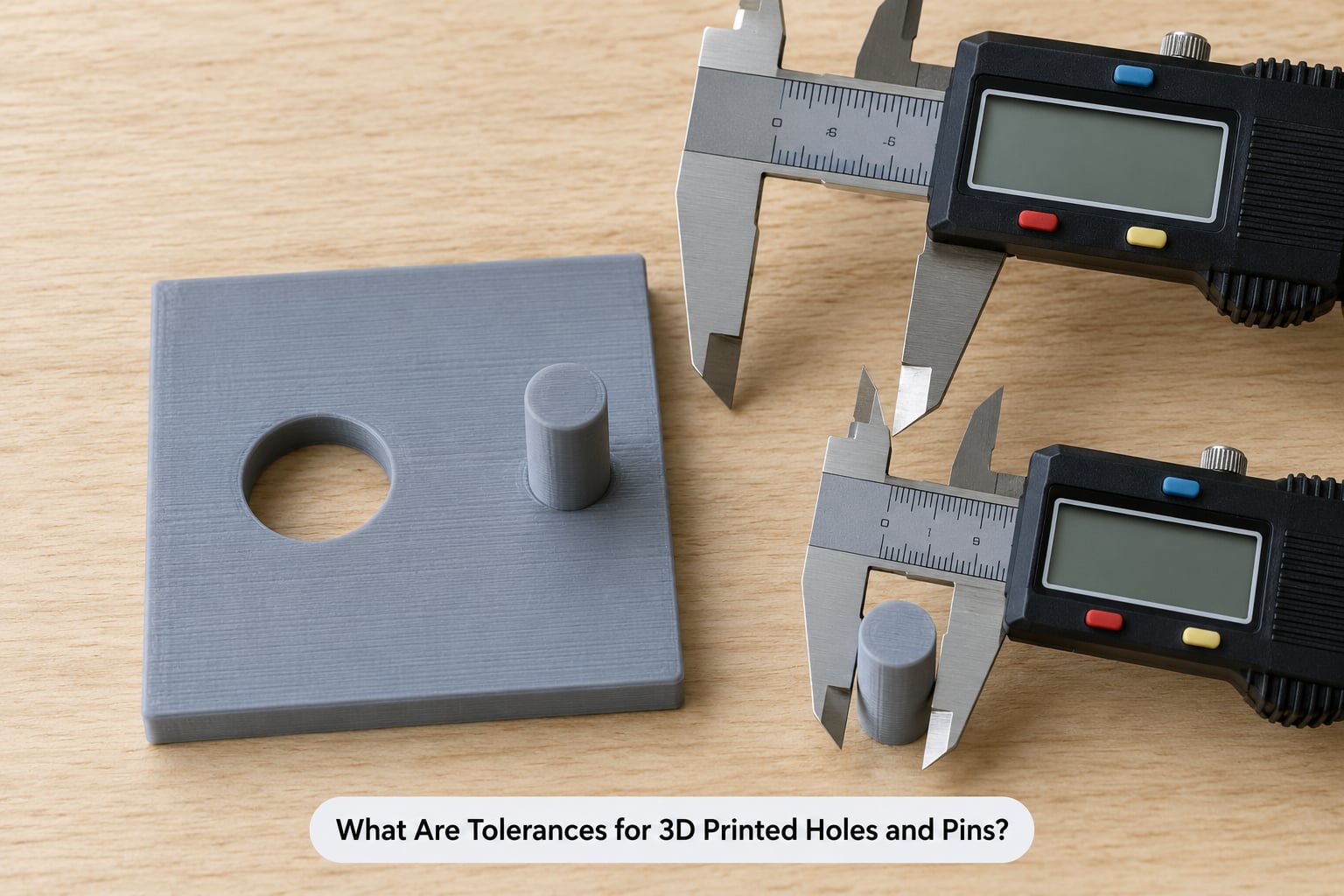
A tolerance is the amount a finished part is allowed to deviate from the nominal dimension in your CAD file. Clearance is the intentional gap you leave between two mating features. People mix the two up constantly, so it is worth being blunt: tolerance describes the printer’s error, clearance describes your decision. You cannot remove printer error, so you design clearance to absorb it.
Tolerances for 3D printed holes and pins versus clearance
If you model a 10 mm pin and a 10 mm hole, your tolerance on that pair might be 0.15 mm per feature on a well-tuned FDM machine. Nominal size plus tolerance means the pin could land anywhere between 9.85 mm and 10.15 mm while the hole lands between 9.85 mm and 10.15 mm too. Modelled to touch, they overlap and jam. Modelled with 0.2 mm of diametral clearance, they cannot touch, so they fit.
Per side or total: how to read a clearance number
This is the single most useful habit on this page. “0.2 mm clearance” on a forum can mean 0.2 mm per side or 0.2 mm across the whole diameter, and that is a factor of two. Always ask which one, and write it into your own notes as total diametral clearance, because that is what goes in the CAD number:
Hole diameter = pin diameter + 2 × clearance per side
An 8 mm pin with 0.2 mm clearance per side needs a 8.4 mm hole. An 8 mm pin with 0.2 mm total clearance needs an 8.2 mm hole. Same words, very different parts.
Why nominal CAD dimensions are not the finished size
Your slicer turns a smooth cylinder into a polygon made of triangles, and the nozzle extrudes a bead that is wider than the line the toolpath describes. Both push material inward, so printed holes run small and printed pins run large. Anything with a nominal dimension under about half a nozzle width also gets rounded off by the toolpath geometry itself. Nominal size is where you start, never where you finish.
How Do You Specify a Hole-and-Pin Fit?
You specify a fit by picking a fit class and then converting it into one hole diameter and one pin diameter. Everything else — chamfer, orientation, material offset — is a refinement on top of that choice.
The fit classes you actually need in printed assemblies
Machinists use ISO fit classes, and you can borrow the idea without the paperwork. For printed parts, five labels cover almost everything:
- Press fit — the pin has to be pushed in with force. Usually a small interference or a heavy chamfer plus heat. Works best in PETG or on a resin print, and it makes disassembly painful.
- Transition fit — the parts sit still by friction but still turn or slide with a thumb. Very hard to hit repeatably on FDM.
- Sliding fit — free movement with no wobble. This is the default for a pin in a hole.
- Loose fit — visible gap, only useful when you need parts to swap freely or where accuracy is unimportant.
- Snap fit — a cantilever that flexes past a hook. Clearance is 0.3 mm per side plus geometry that is deliberately flexible.
Line-to-line, meaning zero nominal clearance, only makes sense on printed-in-place models where both features come from the same layer and the same plastic, and even there it is a best case, not a guarantee.
Hole-as-master: put the error on the hole, not the pin
Design the pin at its nominal size and put all the clearance on the hole. The reason is practical: if the hole is too small you have thrown away the part, while if the pin is slightly oversize it still fits and the joint just feels a little tighter. Oversizing one hole also means the pin stays a clean cylinder that reads well in a slicer preview and measures consistently on your calipers.
One warning: every millimetre you add to a hole diameter weakens the wall around it, so do not chase a press fit on a part that has to survive handling. A one millimetre wall around an interference-fit pin will split on assembly long before the fit is right.
Recommended Starting Clearances by Process and Material
Use the tables below to pick a number, then verify it with a coupon. Every value is total diametral clearance, the gap across the hole, with the per-side figure in brackets.
Starting clearance by fit type
| Fit type | Total clearance (mm) | Per side (mm) | Total (inches) | How it behaves |
|---|---|---|---|---|
| Press fit | 0 to 0.1 | 0 to 0.05 | 0 to 0.004 | Needs force or heat to assemble |
| Transition fit | 0.1 to 0.2 | 0.05 to 0.10 | 0.004 to 0.008 | Holds by friction, moves by hand |
| Snug fit | 0.2 | 0.10 | 0.008 | Slides with light hand pressure |
| Sliding fit | 0.3 to 0.4 | 0.15 to 0.20 | 0.012 to 0.016 | Free running, no wobble |
| Loose fit | 0.5 to 0.6 | 0.25 to 0.30 | 0.020 to 0.024 | Visible gap, swaps freely |
The 0.2 mm snug figure is the community consensus for FDM and it lines up with what makers repeat on the Prusa forums, where the standing rule is to add roughly 0.2 mm to features above about 3 mm for a normal fit. A long-running thread on r/3Dprinting puts the rule of thumb for slots at 0.3 mm or less depending on how well the machine is calibrated, which lines up with the sliding fit row.
Material adjustments on top of the baseline
The PLA row is the baseline. Every other material shifts from there, and the shifts are one-directional enough to be worth memorising.
| Material | Adjustment from the PLA baseline | Why |
|---|---|---|
| PLA | Baseline | Stiff, low shrinkage, well understood |
| PETG | Add 0.05 to 0.10 mm per side | Flows into small features and shrinks a little more as it cools |
| ABS and ASA | Add 0.05 to 0.10 mm per side | Higher thermal contraction plus warping around the feature |
| TPU | Add 0.15 to 0.25 mm per side | Soft material deforms on contact, so nominal contact is never real contact |
| Resin, standard | Subtract 0.05 to 0.10 mm per side | Holes shrink slightly on cure, pins come out near nominal |
If you print PETG parts that handle liquid or food, check the filament’s own documentation first. A clearance number has nothing to say about whether the material is food-safe, and a printed cup is porous enough that claims matter.
Tolerance ranges by print process
Process sets the floor. You can be beautifully calibrated on FDM and still never reach resin accuracy, so pick clearances that your machine can physically deliver.
| Process | Typical X/Y tolerance | Typical Z tolerance | Smallest reliable feature |
|---|---|---|---|
| FDM, 0.4 mm nozzle, 0.2 mm layer | ±0.2 to ±0.3 mm | ±0.1 to ±0.2 mm | About 1.5 to 2 mm |
| FDM, 0.4 mm nozzle, 0.1 mm layer | ±0.15 to ±0.25 mm | ±0.05 to ±0.1 mm | About 1 to 1.5 mm |
| SLA resin | ±0.05 to ±0.1 mm | ±0.05 to ±0.1 mm | About 0.5 mm |
| SLS or powder bed | ±0.1 to ±0.2 mm | ±0.1 to ±0.2 mm | About 1 mm |
Whatever process you are on, keep clearance at or above your process tolerance. Asking for a 0.05 mm clearance on an FDM part is asking for a coin flip, not a fit.
What Affects 3D Printing Tolerances?
Five things move your fit more than anything else: how the hole is made, how big your layers are, what the plastic does as it cools, how the part is oriented, and how well the machine is calibrated. Work through them in that order.
Two reasons printed holes come out smaller
- Bead swell. The nozzle lays down a bead wider than its programmed path. On the inside of a hole that means the inner perimeter pushes outward into the hole, shrinking it. This is the dominant effect on FDM, typically 0.1 to 0.3 mm on a normal hole.
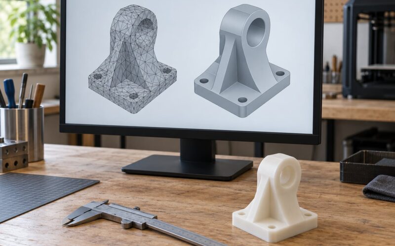
- Polygon approximation. Your STL is a stack of flat triangles approximating a circle. Depending on whether the fit is inscribed or circumscribed, a nominal 10 mm circle can measure anywhere from about 9.85 mm to 10.15 mm before the printer does anything at all.
Pins suffer the same two effects in the opposite direction: the outer perimeter swells outward, so a printed pin is usually a touch larger than nominal. Two undersized features in the same direction is why a nominal-fit assembly fails loudly on the first try instead of drifting slightly.
Layer height, nozzle size and the limits of X/Y and Z accuracy
Layer height sets the vertical resolution. A hole drilled by the toolpath in X/Y can come within a fraction of a layer, but a vertical pin is built up in Z, so the slot around it has to be wider than the pin by up to one full layer height or it will bind. Print a 0.2 mm-layer pin that needs to slide in a slot and you are really asking for a 0.2 mm Z allowance on top of your clearance.
Nozzle diameter is the other hard floor. With a 0.4 mm nozzle you can still resolve a thin internal wall, but a 2 mm hole with 1.5 mm walls leaves you nothing to hold calibration error, and small holes are where slicer gap compensation fights you. If you need features below 2 mm, that is an argument for a smaller nozzle or a resin printer, not for a clever slicer setting.
Material shrinkage, cooling and orientation
Material contracts as it cools, and the contraction is not uniform. A small part cools quickly and shrinks a different amount than a large one, and a hole near the middle of a plate can end up a different size from the same hole near the edge. Shrinkage of 0.3 to 1.5% across common filaments is enough to move a 20 mm feature by 0.06 to 0.3 mm, which is most of your clearance budget on its own.
Orientation decides shape, not just strength. A hole printed vertically has a faceted wall whose width varies layer to layer. A hole printed horizontally suffers from sag between the top and bottom of the bore, which is why so many makers deliberately print pins standing up and drill or ream horizontal seats afterward.
| Orientation | Effect on hole roundness | Clearance needed |
|---|---|---|
| Hole axis vertical (bore along Z) | Faceted and slightly lumpy between layers | Baseline clearance |
| Hole axis horizontal, printed flat | Oval, sag on the upper surface | Baseline plus 0.1 to 0.2 mm |
| Pin axis vertical | Best pin roundness, full layer-height error in Z | Baseline plus one layer height |
| Pin axis horizontal | Round in section but droops along its length | Avoid for fits that must be concentric |
Calibration, first layer and measurement error
An uncalibrated flow rate and an uncalibrated first layer both show up directly in fit. Too much flow and your holes print tighter than designed; too little and they loosen. The first layer squashes outward under the nozzle, which is the elephant’s foot problem: a hole at the very bottom of a part can be effectively 0.2 mm smaller than the same hole ten layers up.
Finally, remember that measurement has its own error. A 0.01 mm caliper reading is believable. A value you read off a slicer preview, a photograph, or a fanet’s opinion of a fit tells you much less than it appears to. Measure the part, not the screen.
How to Model Holes and Pins for Reliable Fit
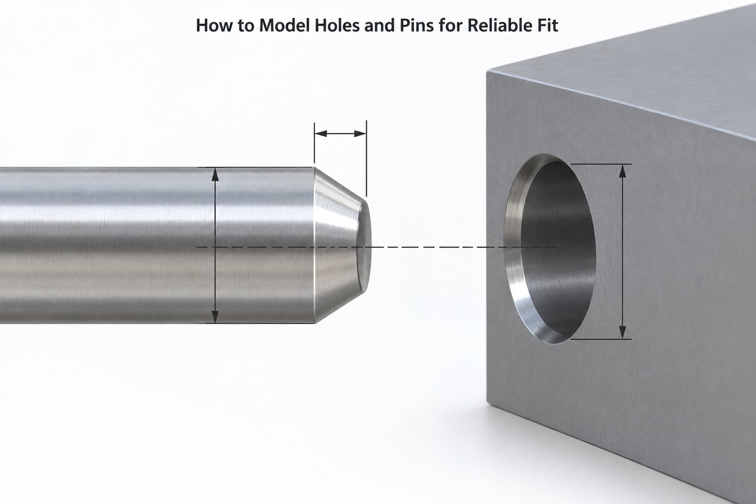
Good hole-and-pin design is about five decisions made in the right order. Skipping straight to the diameter is how people end up recalibrating by reprinting the whole assembly twice.
Use the hole as the master dimension
Model the pin at nominal, add your chosen clearance per side to the hole, and write both numbers in the part description so you can find them after the print. In a parametric model this is one expression — hole = pin + 2 × clearance — so you can sweep the clearance variable and reprint the whole coupon family from one parameter.
Chamfer every hole you plan to insert into
A 0.5 mm chamfer at 45 degrees on the top of the hole is the single highest-value feature you can add. It guides the pin in, it hides an out-of-round opening, and it removes the risk that a slightly undersized top layer stops the pin dead. Most fit failures caused by ovality disappear once the lead-in is chamfered, which means you can often keep your clearance tighter than you think.
Do not model more precision than you can measure
A hole specified to 10.000 mm tells you nothing that 10.0 mm does not. Use one or two decimal places, round your pin diameter to a sensible size, and pick a clearance that is a round number you can subtract on the calipers without a magnifier. Precision you cannot verify is just a worse way of being wrong.
Choose the axis orientation last, for the fit
Pick the fit class first, then orient so the hole is vertical and the pin is vertical where the part allows it. If the geometry forces a horizontal bore, plan for a reamed or drilled seat after printing rather than hoping the printed bore is round enough.
How to Test and Adjust a Hole-and-Pin Fit
The coupon is how you replace guesswork with a number for your exact printer, filament and settings. Five steps, about an hour of printing, and it pays for itself the first time an assembly goes together.
Build the coupon
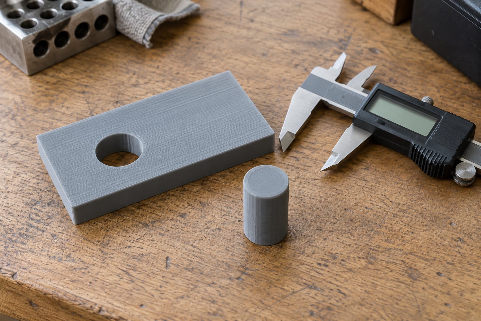
Model a flat plate with five holes of the same diameter, each offset from a nominal pin by 0.0, 0.1, 0.2, 0.3 and 0.4 mm per side. Use pin diameters of 3 mm, 6 mm and 10 mm so you can see whether the fit varies with size, and print one pin at each of those three diameters to stand in the plate. Print it with the same material, layer height and orientation as your real part, not as a convenient test. Test coupons printed in different conditions tell you nothing useful.
Measure and read the result
- Measure each hole across two axes with calipers. An oval hole shows up immediately as two different numbers, and that difference is your ovality figure.
- Measure the pin diameter at the same points on the coupon.
- Push the pin into the tightest hole it enters by hand. Note the smallest hole that accepts it without forcing.
- Read off your real per-side clearance as (hole minus pin) ÷ 2. That is your machine’s number, not a forum’s number.
- Print the real part with that clearance, then remeasure the first hole and pin before committing to the full assembly.
Pin gauges, or a set of drill bits in the diameters you use, tell you the same thing faster once you own them. Feel gauges answer a different question and are the right tool when your real problem is a flat lid against a flat surface rather than a round pin in a round hole.
Common Hole and Pin Fit Problems and Fixes
Nearly every failed fit falls into one of these five patterns. Find your symptom, then change one variable at a time rather than adjusting the model and the slicer together.
| Symptom | Likely cause | Fix |
|---|---|---|
| Pin will not insert at all | Hole printed undersized from bead swell, or pin oversize | Add 0.1 mm per side, run a flow calibration test, add a lead-in chamfer |
| Pin inserts partway then jams | Horizontal hole ovality or sag, no chamfer | Chamfer both ends, print the bore vertically, or ream it after printing |
| Part rattles or falls apart | Clearance too generous, or pin worn round in service | Drop 0.1 mm per side, print the pin in PETG for wear resistance |
| Fit works in one rotation only | Out-of-round hole from layer stepping or first-layer squash | Reprint vertical, add clearance, check that the pin is not the oval part |
| Same model fit last week, jams today | Different filament, wet filament, or unlevelled bed shifting the first layer | Dry the filament, re-tram the bed, and calibrate flow before changing the model |
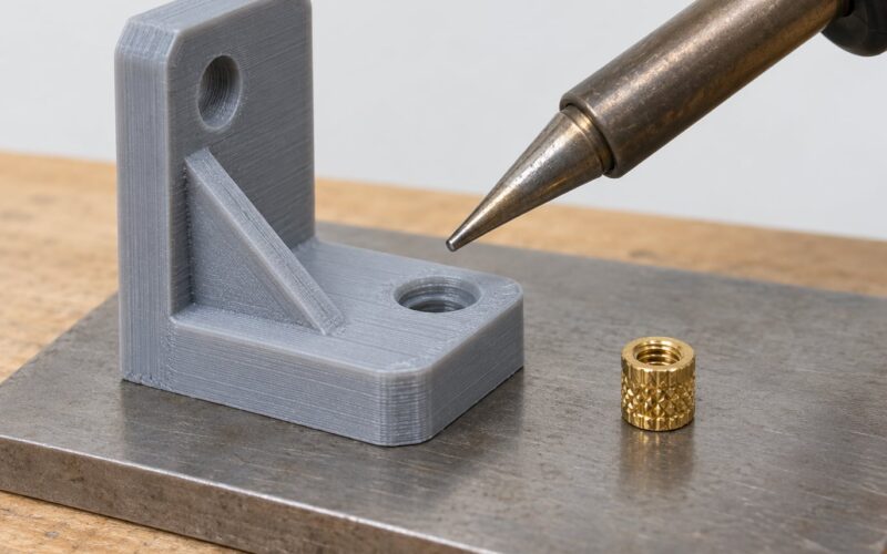
| Threads strip or jam on the first turn | Printed threads are not cut threads; clearance is negative on the flanks | Model threads with 0.2 to 0.3 mm flank clearance, or switch to a heat-set insert |
Two of these deserve extra attention. Threads are the most common place where a printed part fails to assemble at all, because printed threads follow a different helix convention than machined ones; a heat-set brass insert removes the problem entirely and is my default for anything that gets fastened more than a handful of times. And a fit that changed between prints is almost never a tolerance problem, so do not touch the model until you have ruled out wet filament and bed levelling.
One last thought on when to stop printing and switch. If your fit needs to hold load, survive heat, or repeat within 0.05 mm, printing is the wrong process and reaming or CNC machining the bore is not a workaround but the correct answer.
Frequently Asked Questions
What is the recommended tolerance for a tight fit in 3D printing?
For a snug pin-in-hole fit on a well-calibrated FDM machine, use 0.2 mm of total diametral clearance, which is 0.1 mm per side. For a free-sliding fit go to 0.3 to 0.4 mm total, and for a press fit drop to 0.1 mm or zero. Always add a 0.5 mm chamfer to the top of the hole. On resin, subtract roughly 0.05 to 0.10 mm per side from these figures.
Why do my 3D printed holes come out smaller than the CAD model?
Two separate effects are at work. Bead swell happens because the nozzle extrudes a bead wider than the programmed toolpath, so the inner perimeter of a hole pushes outward and shrinks it, typically by 0.1 to 0.3 mm on FDM. Second, your STL approximates a circle with flat triangles, which alone can take a nominal 10 mm hole down to about 9.85 mm. Design the hole larger than the pin and both effects stop mattering.
How do I calculate hole and pin clearance in CAD?
Use hole diameter equals pin diameter plus two times the clearance per side. So an 8 mm pin with 0.2 mm clearance per side gets an 8.4 mm hole. In a parametric model, set clearance as a single variable and drive the hole from it so you can sweep values and reprint the whole coupon family. Put every clearance on the hole and keep the pin at nominal, because an oversize hole is recoverable and an oversize pin is scrap.
How do I run a 3D printing tolerance test?
Print a flat coupon with five holes of identical diameter offset by 0.0, 0.1, 0.2, 0.3 and 0.4 mm per side from a matching pin, ideally at three pin diameters such as 3, 6 and 10 mm. Measure each hole across two axes with calipers to catch ovality, then find the smallest hole the pin enters by hand. Divide hole minus pin by two and that is your per-side clearance for this machine and material.
Should I make the hole bigger or the pin smaller to fix a tight fit?
Make the hole bigger. Shrinking the pin leaves you with no margin below nominal, so any bead swell on the pin’s outer perimeter puts you back in a jam, and an undersize pin is also harder to measure accurately. Oversizing the hole by the same amount absorbs both the hole shrinking and the pin growing, which are the two effects that actually happen on a real print.
Can you print a tight-fitting hole and pin on the same part?
Sometimes, but not reliably, and it depends on the process. Print-in-place models where both features come from the same layer of the same plastic are the most likely to work, because both features see identical conditions and the geometry stays put through cooling. Even then, treat any nominal line-to-line fit as a best case rather than a guarantee, and test it on a small coupon before committing to a whole assembly.
Start With the Coupon, Not the Assembly
If you take one thing from this guide, make it the coupon. A five-hole test plate with 0.0 to 0.4 mm offsets takes an hour to print and gives you a clearance number that is true for your machine, your filament and your settings this week, rather than a forum consensus that may not apply to either.
Until then, start at 0.2 mm total clearance for a snug fit, put all of it on the hole, chamfer the hole by 0.5 mm, and print the pin standing up. Adjust from there based on what your calipers say about the part you actually made.