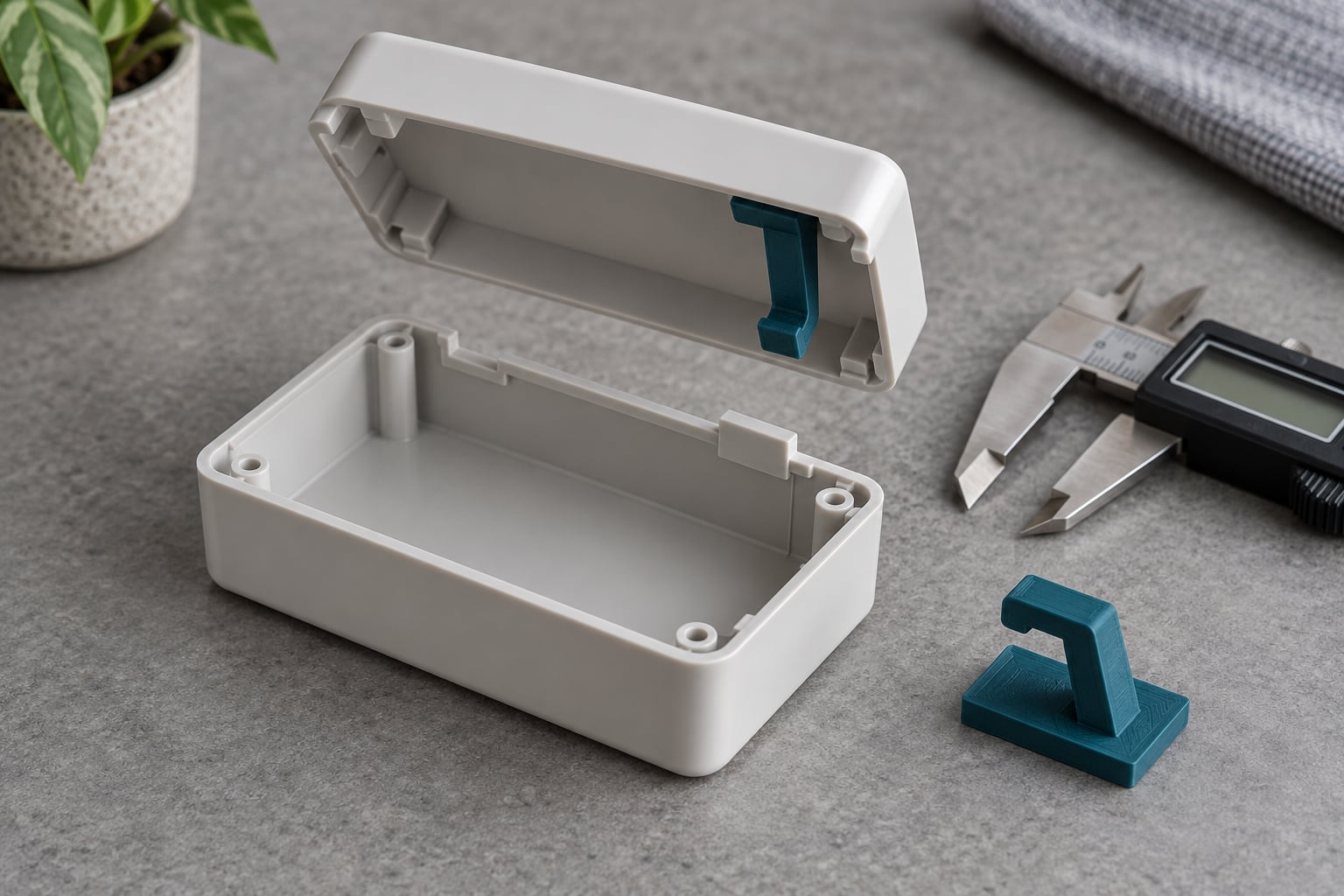
A snap-fit joint is a fastener-free connection: a flexible hook on one part deflects as it enters a mating part, then drops into an undercut and holds the two together. To design snap fit joints for 3D printing that survive assembly, you orient the flexing arm so its bending runs along layer lines, widen it instead of thickening it, fillet the root, and leave enough clearance for your printer’s variation. Budget an hour for a test coupon before you commit to the full part.
Most failed enclosures trace back to one of two things: an arm printed upright, so it splits cleanly along a layer boundary, or an arm that was made thicker when it should have been made wider. Both are geometry problems, not slicer problems. Get the geometry right and the same file works on a hobby printer and in a service bureau.
Table of Contents
- 1What You Need
- 2Step-by-Step: How to Design Snap Fit Joints for 3D Printing
- 31. Define the Joint’s Loads and Motion
- 42. Choose a Snap-Fit Geometry
- 53. Set the Initial Dimensions for Your Snap Fit Joints
- 64. Add Proper Undercuts and Relief
- 75. Check Wall Thickness and Print Orientation
- 86. Design for Materials and Manufacturing Tolerances
- 97. Print and Test a Calibration Coupon
- 108. Refine and Validate the Final Part
- 11Common Mistakes
- 12Frequently Asked Questions
- 13What clearance should I use for a 3D-printed snap fit?
- 14Are snap-fit joints strong enough for repeated 3D-printed assemblies?
- 15What layer height is best for printable snap-fit parts?
- 16How do I make a snap fit stronger without making assembly difficult?
- 17Should snap fits be printed with supports?
- 18How do I prevent a snap fit from cracking between layers?
- 19Conclusion
What You Need
You do not need expensive software or a simulation package to build a working printed snap fit. You need a parametric CAD tool, a basic idea of how much force the joint carries, and about twenty minutes of printing time for a test coupon.
- CAD software with a fillet tool and a shell or offset operation. Fusion 360, SolidWorks, FreeCAD, Onshape and SolveSpace all handle cantilever snap arms. Fusion 360 and FreeCAD also have free snap-fit component libraries you can adapt instead of modeling from zero.
- Your printer’s real dimensional variation. Measure a 20 mm test block with calipers across several prints, not once. The spread between your best and worst print is your clearance budget.
- Nozzle diameter and layer height. A 0.4 mm nozzle and 0.2 mm layers cannot resolve the 0.5 mm fillet detail or a sharp 1 mm hook the way a 0.25 mm nozzle can.
- Material data, at least roughly. Elongation at break matters more than tensile strength for a flexing arm. PLA elongates around 3-5 percent, PETG around 5-8 percent, nylon PA12 well above 15 percent. A material that snaps at 4 percent strain cannot flex far enough to pass an undercut, whatever your geometry.
- A test coupon workflow. One flat plate carrying four or five snap beams with different thicknesses and lengths, printed once, tells you more in ten minutes than a week of guessing.
Step-by-Step: How to Design Snap Fit Joints for 3D Printing
1. Define the Joint’s Loads and Motion
Before you model anything, write down how the parts come apart. Direction of assembly, how many times the joint cycles in service, and what it carries when closed decide everything downstream.
A battery cover that opens once a year and a tool holder clicked on and off all day want different geometries. The battery cover wants a deep, stiff hook with a modest undercut. The tool holder wants a shorter, more flexible arm with enough engagement to survive being yanked sideways, which means the shear load has to be shared by more than one hook and some alignment lugs.
Note three numbers before you start: the pull-off force you need, the worst load direction, and how many cycles you expect. If the joint must carry real weight or cannot fail safely, use screws or heat-set inserts instead. Snap fits fail suddenly and without warning, and printed threads do not.
2. Choose a Snap-Fit Geometry
Five geometries cover almost every printed joint you will model. Each trades flexibility against how much space the mechanism needs.
Cantilever (L-shaped). The default. One flexible beam with a hook at the end, bending vertically to engage. Best for enclosures, panels and covers. It uses the least material and the least wall thickness, and it is the easiest to print flat in the XY plane.
Tapered or trapezoidal cantilever. Same geometry, thicker at the root and thinner at the tip. The taper roughly halves the peak stress for the same deflection, which is the difference between a hook that survives and one that snaps on the third assembly. If you only ever model one type, model this one.
U-shaped. Two arms that bend toward each other around a central post. Stiffer than a single cantilever and it takes a lot of space, so it suits larger clips where you cannot afford a thin arm.
Annular. A ring of snap arms around a lid or bottle cap. Force is shared all the way around, so per-arm stress is low, but hoop strain means the material stretches in two directions at once. Keep the number of arms between eight and twelve; too few and the ring ovalizes.
Torsional. A C-shaped ring that flexes around its circumference. Very high cycle life because no single fiber line takes the load, but it demands careful orientation and is harder to print than a flat cantilever.
Skip the bead or rib snap if you are printing at home. Beads need tight concentric perimeters and consistent infill, and they fail early on a hobby printer because of drip or under-extrusion.
3. Set the Initial Dimensions for Your Snap Fit Joints
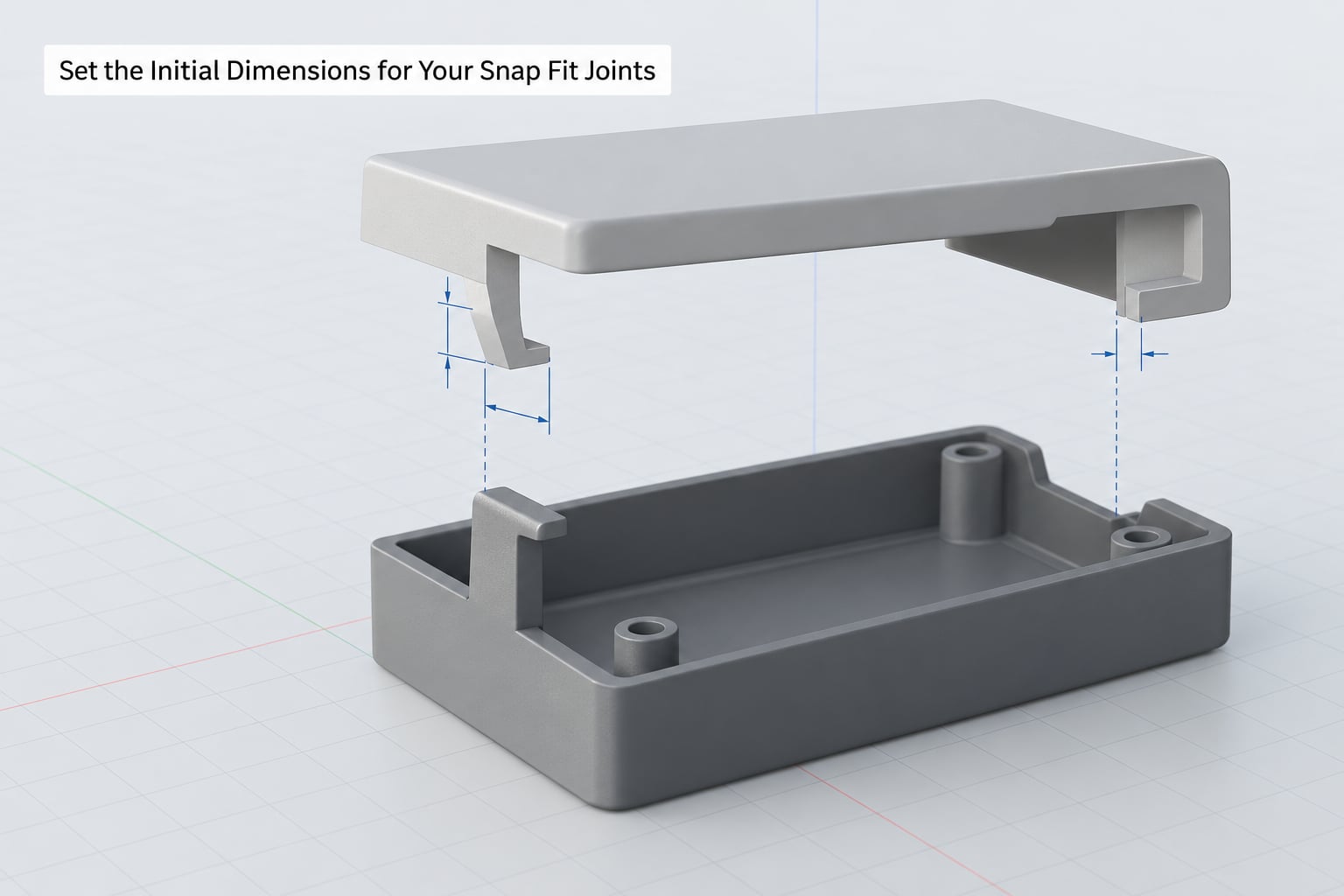
Start from conservative printable numbers, then calibrate. These are starting points for a 0.4 mm nozzle in FDM, not laws of nature.
- Base thickness (the arm thickness in Z): 1.0-1.2 mm. Below about 0.8 mm the arm is thinner than most layers can resolve reliably and splits along layer lines. At 0.2 mm layers, 1.0 mm is five clean courses.
- Length-to-thickness ratio: start at 5:1. A 6 mm long arm at 1.2 mm thick flexes. A 3 mm long arm at 1.2 mm thick is a rigid peg that either snaps the hook or the part. This ratio is the single most useful number in the whole design, and it is the one forum advice keeps converging on.
- Width: minimum 5 mm, 8-12 mm for real retention. Widening an arm increases its moment of inertia far faster than increasing its thickness does, because bending resistance scales with width linearly but with thickness cubed. Doubling width doubles stiffness; doubling thickness multiplies it by eight. If an arm is too stiff, widen the geometry before you thin the base.
- Root fillet: radius 0.5 times the base thickness or more. The fillet spreads stress across several layers instead of concentrating it at one sharp corner, which is where most printed hooks actually break.
- Lead-in angle: 30 to 45 degrees. This is the ramp the hook slides up during insertion. Shallower means easier assembly but more material to flex.
- Retention angle: 60 to 90 degrees. This is the face that holds the joint closed. It should be steeper than the lead-in so the stored energy pulls the arm into the undercut instead of back out. A retention angle shallower than the lead-in gives you a joint that creeps open.
- Undercut depth: 0.5 to 0.8 mm for FDM. The depth of the hook beyond the mating face.
If you want to size an arm analytically rather than by coupon, treat it as a rectangular cantilever beam. The second moment of area is I = b x h^3, where b is the arm width and h is the base thickness, and tip deflection under a point load F is roughly F x L cubed divided by 3 x E x I. The h cubed term is why thickness dominates everything. For most printed arms the coupon loop below beats the calculation, because material modulus varies far more between prints than your arithmetic does.
4. Add Proper Undercuts and Relief
An undercut is the recess the hook drops into. Getting it wrong is what makes parts collide on the way in even when the fit looks correct on paper.
Chamfer or round the entire entry edge of the mating opening so the hook has somewhere to go. Add 2 to 3 degrees of draft to the vertical walls of the receiving port so a printed part with a slight dimensional drift still slides in rather than binding on one side. Terminate the arm in an open-ended slot rather than a closed hole, so any stringing or a support scar on the hook tip cannot stop it from seating.
Give the hook tip a generous radius too. A sharp hook tip is a stress raiser and a print artifact collector, and the first thing to break when a user pries the joint open. Extend the arm past the retention face so the deflection happens along the beam rather than at the tip.
5. Check Wall Thickness and Print Orientation
This is where printed snap fits succeed or die. A printed part is far stronger in the XY plane than along Z, because layer adhesion is the weakest bond in the part. Bending an arm that stands upright asks the layer boundary to open, so the arm snaps exactly along that line.
Lay the flexing arm flat so its width runs across X and its length along Y. Then the bending stress acts within the layer plane, and the strongest material direction takes the load. If your part must stand the arm upright, print it in a resin printer or an SLS or MJF process, where parts are close to isotropic, and expect less stiffness than the same design in FDM.
Four or more perimeters through the arm region is worth the extra time. Set the infill to solid inside the arm if your slicer lets you target a region, since 20 percent gyroid infill inside a flexing beam adds nothing useful. A lower layer height in the snap region also helps interlayer bond quality. On a single-part print these settings usually add under two minutes.
Use two or more arms spread around a joint rather than one arm on one side. Two hooks on the far side from the load act as locating lugs that resist the shear that would otherwise lever the joint open.
6. Design for Materials and Manufacturing Tolerances
Clearance is not one number. It depends on your process, your material and how well your machine is calibrated right now.
For FDM, start with 0.3 to 0.5 mm of clearance per side on the sliding fit and treat 0.5 mm as generous. FDM parts vary by a few tenths of a millimeter across a bed and across a spool, so anything tighter will bind at some point in the part’s life. For SLA, SLS and MJF parts, where dimensional accuracy is much better, 0.2 to 0.3 mm per side works.
Material choice changes the fit as much as the geometry does. PLA is stiff and brittle with low elongation, so snap arms in PLA need to be longer and more tapered, or you switch to something tougher. PETG is the usual fix for functional PLA prototypes because it absorbs more strain before tearing. ABS and ASA tolerate heat. Nylon PA11 and PA12 are ductile and fatigue-tolerant, which is why industrial snap fits are nearly always nylon. TPU works as a flexing arm in a two-material print, though multi-material FDM printers rarely bond TPU to rigid filament reliably. Tough resins such as tough 2000-class formulations give you accurate, moderately flexible arms at the cost of a longer UV-aged life.
Watch for creep. A joint held under constant load in PLA or ABS will slowly relax, and a marginal retention angle will drift open over weeks. If the joint carries a sustained load, use a retention angle near 90 degrees and a material with real creep resistance.
7. Print and Test a Calibration Coupon

One coupon replaces most of the guesswork. Make a flat plate about 60 mm square with four or five cantilever arms of the same length and hook, differing only in base thickness or length. Print it flat with the arms in XY, using your normal settings.
Then run a controlled sequence. Insert each arm by hand only, no tools, and note whether it went in without force, needed steady pressure, or refused to go in at all. Next, measure retention: does the part hold against a firm pull perpendicular to the joint? Then measure removal force by feel, from effortless to requiring a fingernail to something you would not do to a printed part. Finally, cycle each surviving arm 50 times and watch for whitening at the root, which is the first sign of fatigue cracking.
You are looking for the arm that inserts with firm but positive pressure, holds under a sideways pull, and comes apart without tools. In practice that is usually two thicknesses apart from the version that broke immediately. Slower printers at lower layer heights usually give a tighter, more consistent coupon, which is why a ten-minute test on a well-tuned machine is worth more than an hour on a rough one.
8. Refine and Validate the Final Part
Take the winning thickness and length back into the CAD file and apply them to the real part. Keep everything else identical so the coupon result transfers. Then print the final assembly and check three things in order.
First, assembly force. Parts should go together with deliberate push and an audible click, then stay put without a fastener. Second, retention under load in the direction your part actually sees in use, not just straight off. Third, the surface. Inspect the root of each arm for layer separation, cracking or a visible split line along the layer boundary. A root fillet at 0.5 times base thickness or more should prevent this; if you still see a crack, the arm is too thick for its length or the infill region is too sparse.
Write down the numbers that worked: base thickness, length, width, undercut depth and clearance. Snap fits are rarely reused at exactly the same size, but the ratios carry over. My own rule is a 5:1 length-to-thickness ratio, 8 mm width, 1.0 mm base, and 0.4 mm clearance per side, and then I move each of those by one increment until the coupon tells me which is right.
Common Mistakes
Every failure below has a geometric cause that shows up in the CAD file before it ever reaches the printer.
The arm breaks at the root on first or second assembly. Usually PLA, usually too short for its thickness. Lengthen the arm until you hit roughly a 5:1 length-to-thickness ratio, add a taper so the root is thicker than the tip, and increase the root fillet. If it still breaks, change material to PETG or nylon rather than continuing to shrink the base below 1 mm.
The arm splits cleanly along a layer line. The arm is standing upright in Z. Rotate the part so the arm lies flat, or raise perimeters through the arm region. If the design forces a vertical arm, that is a strong argument for a resin or powder-bed process instead of FDM.
The parts will not go together at all. Clearance is too tight, or the entry is chamfered too gently. Add 0.1 to 0.2 mm per side and increase entry chamfer and draft before you reduce anything else.
The joint falls apart or looks broken. Clearance is too loose, or the retention angle is shallower than the lead-in. Tighten the fit and steepen the retention face to 80 or 90 degrees so the arm is pulled into the undercut.
The hook tip breaks instead of the arm flexing. The hook is acting as a cantilever on its own, usually because the arm stops short of the retention face. Extend the beam past the undercut and round the tip.
The arm is impossibly stiff and the joint will not open. It was thickened instead of widened. Halve the base thickness, or better, double the width and keep the base where it is.
The fit worked once and failed on the next print. You designed to nominal rather than to variation. Print the coupon again on a different day, take the worst fit, and set your clearance to that.
The joint creaks open or slowly relaxes. Creep under sustained load in PLA or ABS. Steepen the retention angle, widen the hook face, and move to PETG or nylon if the load is permanent.
The snap geometry is unreachable in the assembled state. The hooks point inward so tightly that the mating part cannot engage them. Open the joint or place the hooks so they engage on the final movement, and check the assembly path in CAD before printing.
Frequently Asked Questions
What clearance should I use for a 3D-printed snap fit?
For FDM, start with 0.3 to 0.5 mm of clearance per sliding side and treat 0.5 mm as generous. Printed parts vary by a few tenths of a millimeter between prints, so tighter fits bind eventually. SLA, SLS and MJF parts hold accuracy better, so 0.2 to 0.3 mm per side works there. Always add entry chamfer and draft so the hole cannot bind on one side.
Are snap-fit joints strong enough for repeated 3D-printed assemblies?
Yes, in the right geometry and material. A tapered cantilever with a generous root fillet survives thousands of cycles in PETG or nylon. In PLA, expect tens to a few hundred before fatigue cracking shows at the root. Printed snap fits fail suddenly rather than gradually, so never use one as the sole restraint on a heavy or safety-critical load.
What layer height is best for printable snap-fit parts?
Use 0.15 to 0.2 mm layers around the snap region. Finer layers give better interlayer bond quality, which is what resists the bending load, and they resolve the hook tip and root fillet more cleanly. Going below 0.15 mm rarely helps a snap fit and simply lengthens the print. A 1.0 mm base thickness at 0.2 mm layers gives five solid courses through the beam.
How do I make a snap fit stronger without making assembly difficult?
Widen the arm before you thicken it. Bending resistance scales with width linearly and with thickness cubed, so a wider arm at the same thickness is far stiffer without making the insertion force climb. Adding a taper so the root is thicker than the tip, and increasing the root fillet to at least half the base thickness, buys more strength at no cost to assembly.
Should snap fits be printed with supports?
Almost never, and usually they should not be. If a snap fit needs support, the joint is oriented wrong. Rotate the part so the flexing arm lies flat in the XY plane, which also puts the bending stress along the strongest material direction. Design the hook so it is reachable from above and terminates in an open slot rather than a closed hole, so no support material is ever needed under the arm.
How do I prevent a snap fit from cracking between layers?
Lay the arm flat so bending runs within a layer, keep the base thickness at 1.0 mm or more, and use four or more perimeters through the arm region. Solid infill in the snap zone helps if your slicer can target it. A root fillet of 0.5 times the base thickness spreads the stress across several layers, and switching from PLA to PETG adds the strain capacity that prevents the crack in the first place.
Conclusion
Designing snap fit joints for 3D printing comes down to a short sequence: define the load and cycles, pick a tapered cantilever unless you have a reason not to, set a 5:1 length-to-thickness ratio with an 8 mm width and a 1.0 mm base, fillet the root at half the base thickness, chamfer the entry, hold clearance to 0.4 mm per side on FDM, and lay the arm flat in the XY plane.
Then print a small coupon with four or five beam variations, test insertion and removal by hand, and move one dimension at a time until the joint clicks together firmly and opens without tools. That loop takes minutes and saves the part. Start with the conservative model, and let the coupon set the final number rather than your assumptions.